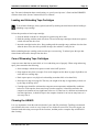
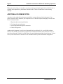
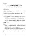
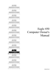
1
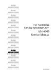
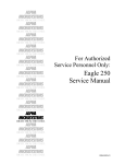
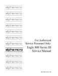
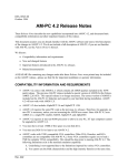
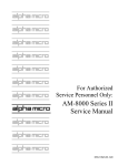
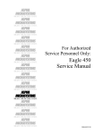
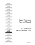
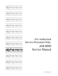
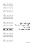
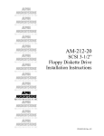
$/3+$
0,&526<67(06
5,*+7 )520 7+( 67$57
$/3+$
0,&526<67(06
5,*+7 )520 7+( 67$57
$/3+$
0,&526<67(06
5,*+7 )520 7+( 67$57
$/3+$
0,&526<67(06
5,*+7 )520 7+( 67$57
$/3+$
0,&526<67(06
5,*+7 )520 7+( 67$57
$/3+$
0,&526<67(06
5,*+7 )520 7+( 67$57
$/3+$
0,&526<67(06
AM-629
High Capacity ¼”
Streaming Tape Drive
Installation Instructions
5,*+7 )520 7+( 67$57
$/3+$
0,&526<67(06
5,*+7 )520 7+( 67$57
$/3+$
0,&526<67(06
5,*+7 )520 7+( 67$57
$/3+$
0,&526<67(06
5,*+7 )520 7+( 67$57
$/3+$
0,&526<67(06
5,*+7 )520 7+( 67$57
$/3+$
0,&526<67(06
5,*+7 )520 7+( 67$57
$/3+$
0,&526<67(06
5,*+7 )520 7+( 67$57
PDI-00629-00, Rev. A01
FIRST EDITION: June 1998
To re-order this document, request part number PDI-00629-00
FCC Notice
This equipment has been tested and found to comply with the limits for a Class A digital device, pursuant to Part 15 of the FCC Rules.
These limits are designed to provide reasonable protection against harmful interference when the equipment is operated in a
commercial environment. This equipment generates, uses and can radiate radio frequency energy and, if not installed and used in
accordance with the instruction manual, may cause harmful interference to radio communications. Operation of this equipment in a
residential area is likely to cause harmful interference in which case the user will be required to correct the interference at his own
expense.
Canadian Department of Communications Compliance Statement
This equipment does not exceed Class A limits per radio noise emissions for digital apparatus set out in the Radio Interference
Regulations of the Canadian Department of Communications. Operation in a residential area may cause unacceptable interference to
radio and TV reception requiring the owner or operator to take whatever steps are necessary to correct the interference.
Avis de Conformité aux Normes du Ministère des Communications du Canada
Cet équipment ne deapsse pas les limits de Classe A d'émission de bruits radioélectriques pour les appareils numeriques tels que
prescrites par le Règlement sur le brouillage radioélectrique établi par le ministère des Communications du Canada. L'exploitation faite
en milleu résidential peut entrainer le brouillage des réceptions radio et tele, ce qui obligerait le propriétaire ou l'opératour à pendre les
dispositions nécessaires pour en éliminer les causes.
Battery Warning
CAUTION: Danger of explosion if battery is incorrectly replaced. Replace only with the same or equivalent type recommended by the
manufacturer. Discard used batteries according to the manufacturer's instructions.
ATTENTION: Il y a danger d'explosion s'il y a replacement incorrect de la batterie. Remplacer uniquement avec une batterie du même
type ou d'un type recommandé par le constructeur. Mettre au rébut les batteries usagées conformément aux instructions du fabricant.
For AM-6000 systems, replace batteries with Panasonic or Ray-O-Vac BR1225 only. Use of another battery may present a risk of fire
or explosion. Replacement batteries may be ordered from your authorized Alpha Micro reseller.
Electrical Warning
This equipment contains components that can be damaged by static electricity. Follow all electronic discharge precautions when
handling the equipment. For example, touch the metal back panel of the CPU or peripheral chassis to dissipate any electrical charge
before touching the circuit boards or equipment within the chassis. After turning off power, before you open your computer chassis,
unplug the cord from the electrical outlet to guard against electrical shock.
SOFTWARE SECURITY DEVICE IDENTIFICATION NUMBER: _________________
The Alpha Micro Software Security Device (SSD) is a customized integrated circuit that personalizes the computer, providing identity
verification for it. Certain Alpha Micro and non-Alpha Micro software may require that your computer contain an SSD in order to run
software that has been customized to run only on your computer.
Please enter the identification of your SSD above. The SSD identification number should be on your computer ID label under "SSD
Serial No." (Another way of finding the number is to look at the SSD itself. The SSD is located in an integrated circuit location on the
CPU board; its identification number is printed on the SSD itself.) Software vendors may ask you for the SSD number if they are
customizing software to run only on your computer.
This document may contain references to products covered under the following U.S. Patent Number(s): 4,530,048
ALPHA MICROSYSTEMS
2722 Fairview Street
Santa Ana, CA 92704
Table of Contents
INTRODUCTION
PRODUCT DESCRIPTION
TOOLS REQUIRED
PREPARING THE AM-629 FOR INSTALLATION
Setting the SCSI ID
SCSI BUS TERMINATION
External SCSI Bus Termination
Internal SCSI Bus Termination
TERMINATION POWER
INSTALLING THE AM-629
Pedestal and Rack Mount Computer Installation
AM-990 Chassis Installation
Eagle Deskside Chassis Installation
SOFTWARE INFORMATION
Copying the Device Driver Program
Modifying the System Initialization Command File
Testing the Initialization File
Initial System Testing
USING THE AM-629
Reading and Writing Different Tape Formats
Spanning Tapes
Warm Booting
Loading and Unloading Tape Cartridges
Care of Streaming Tape Cartridges
Cleaning the AM-629
ADDITIONAL DOCUMENTATION
1
1
2
2
4
4
4
6
6
7
7
12
13
14
14
14
15
16
16
16
17
17
19
19
19
20
List of Figures
Figure 1 - AM-629 Tape Drive Rear Panel
Figure 2a - External SCSI Terminator - Narrow
Figure 2b - External SCSI Terminator - Wide
Figure 3 - Tape Drive Mounting Assembly
Figure 4 - Plastic Mounting Base
Figure 5 - Metal Support Bracket
Figure 6 - Attaching to Front Bezel
Figure 7 - Peripheral Mounting Rails
Figure 8 - Attaching Mounting Rails to Peripheral
Figure 9 - Boot Switch Settings for Warm Boot
PDI-00629-00, Rev. A01
3
5
5
8
9
10
11
12
13
18
Installation Instructions: AM-629 1/4" Streaming Tape Drive
Page 1
INTRODUCTION
This document describes the installation of an AM-629 (Tandberg SLR5) SCSI 1/4" magnetic streaming
tape drive into an existing Alpha Micro computer system.
If you are installing an AM-629 tape drive into an external subsystem, use the installation
instructions shipped with the subsystem together with the drive-specific instructions found here.
These instructions are written for the experienced Alpha Micro Service Technician, so if you do not feel
comfortable performing the hardware and software procedures discussed below, please contact your
Alpha Micro dealer or the Alpha Micro Technical Assistance Center for help.
PRODUCT DESCRIPTION
AM-629 is the Alpha Micro model name for the Tandberg SLR5 magnetic tape drive. The AM-629 has a
storage capacity of up to 8 GB, depending on the type of data cartridge and compression method used.
The AM-629 can read and write to all of the following types of tape cartridges:
3M Cartridge
DC6525
DC9100 / Magnus 1.0
DC9120 / Magnus 1.2
DC9200 / Magnus 2.0
DC9250 / Magnus 2.5
Sony SLR5
Capacity
525MB
1GB
1.2GB
2GB
2.5GB
4GB or 8GB
These are maximum tape use figures. The actual amount of data you will be able to back up on a tape
depends on the number and size of the files being copied.
See the section “Reading and Writing Different Tape Formats,” later in this document, for
information on using different types of tape cartridges and setting data formats.
The AM-629 streaming tape product installation package consists of the tape drive itself and, possibly, a
mounting kit. Whether you get a mounting kit, and what is included in it, depends on the type of
computer chassis you have. The chart below shows which mounting kit goes with each chassis:
Chassis Type
Rack Mount
Pedestal
AM-990
Eagle Deskside
Mounting Kit
PDB-00625-60
PDB-00625-61
Not required
Not required
Make sure you have the correct mounting kit before you begin. If you’re replacing an existing streaming
tape drive, you don’t need a new mounting kit, regardless of your type of computer. The mounting
hardware for your existing drive will work with the AM-629.
The AM-629 has the same environmental specifications as your computer.
PDI-00629-00, Rev. A01
Page 2
Installation Instructions: AM-629 1/4" Streaming Tape Drive
The AM-629 is supported only on the SCSI-2 bus (either narrow or wide). It is not supported on
the SASI bus found on older AMOS computers.
TOOLS REQUIRED
For most installations, the only tool you will need to install the AM-629 is a #2 Phillips-head
screwdriver.
PREPARING THE AM-629 FOR INSTALLATION
Before installing the AM-629, you should make sure its configuration jumpers are set correctly. These
jumpers are found on the back of the tape drive, as shown in Figure 1. Specifically, you need to set the
jumpers determining the SCSI ID for the drive, and make sure the termination power jumper is set
correctly. The next few sections discuss SCSI IDs and SCSI bus termination.
PDI-00629-00, Rev. A01
Installation Instructions: AM-629 1/4" Streaming Tape Drive
Page 3
This cutout gives access to three SIP-style
terminators. These should not be installed
when an external terminator is used.
BACK PANEL LAYOUT
DC POWER
CONFIGURATION
50-PIN CONNECTOR
PIN #1
TERM POWER (see note)
SEL0
SEL1
SEL2
PARITY (disabled = No jumper
installed for AMOS computers.)
ID 0
ID 2
ID 3
= JUMPER INSTALLED
SEL0
SEL1
SEL2
ID 5
ID 6
SEL0
SEL1
SEL2
SEL0
SEL1
SEL2
SEL0
SEL1
SEL2
SEL0
SEL1
SEL2
ID 4
SEL0
SEL1
SEL2
SEL0
SEL1
SEL2
SCSI ID
JUMPER
SETTINGS
ID 1
NOTE: The drive will supply termination
power to the SCSI bus only when the
"TERM POWER" jumper is installed. Since
the controller provides termination power in
almost all AMOS systems, the "TERM
POWER" jumper should not be installed.
Figure 1 - AM-629 Tape Drive Rear Panel
PDI-00629-00, Rev. A01
Page 4
Installation Instructions: AM-629 1/4" Streaming Tape Drive
Setting the SCSI ID
Each SCSI device attached to the SCSI bus must be set to a unique address. Two SCSI devices cannot
share the same address. The AM-629 is a SCSI-2 device, and can be set to any SCSI ID from 0 through
6. Figure 1 shows the jumper settings for each SCSI ID.
If you have an AM-629 on a computer which doesn’t use CMOS boot settings (that is, it uses
boot ID switches), and you want to be able to warm boot from it, it must be set to a higher SCSI
ID than any other tape device on the SCSI bus.
SCSI BUS TERMINATION
To function properly, the SCSI bus on your computer must be terminated at each end. The SCSI
controller terminates one end of the bus; the opposite end of the bus can be terminated in one of two
ways: 1) using the preferred method—an external terminator, or 2) installing on-board terminators in the
peripheral that's at the other end of the SCSI cable. You should use method 2 only if, for some reason,
you cannot use an external terminator.
External SCSI Bus Termination
The preferred way to terminate the SCSI bus in an AMOS computer is to install an external terminator.
Using an external terminator makes it easier to install an add-on subsystem (like a portable CD-ROM
drive), eliminating the need to remove terminators from a SCSI device inside the computer.
Several different external terminators are available from Alpha Micro:
Part Number
PRA-00222-00
PRA-00222-21
PRA-00222-20
Terminator Type
Narrow, passive
Narrow, active
Wide, active
The type of terminator you need depends on your computer and the SCSI peripherals in it. The AM-629
should function correctly with a passive SCSI terminator. However, the AM-6000 and Roadrunner 060equipped computers require active termination, as do certain other peripheral devices. Generally, if either
the computer or any peripheral in it requires active termination, be sure to use an active terminator.
To use the external terminator, you need to insure none of the SCSI devices inside the computer are
terminated. You also need to follow the guidelines in the section on providing termination power to the
SCSI bus, below.
10 and 21-slot rack mount VME computers have no external SCSI connector. To install an external
terminator, you need a special adapter cable, DWB-10200-01. The connector on this cable is compatible
with the narrow external terminators and also allows you to easily attach a portable CD-ROM drive or
other SCSI device.
Figure 2 shows both narrow and wide SCSI terminators:
PDI-00629-00, Rev. A01
Installation Instructions: AM-629 1/4" Streaming Tape Drive
Page 5
BAIL LOCKS
SI
SC
Figure 2a - External SCSI Terminator - Narrow
PRA-00222-20
EXTERNAL SCSI BUS
TERMINATOR
SCSI CONNECTOR
ON BACK PANEL
Figure 2b - External SCSI Terminator - Wide
The illustrations show two different types of external SCSI connectors:
1. The top picture shows an external narrow SCSI connector and bail locks for holding the
terminator in place. The terminator is installed by plugging it onto the connector, then latching
the bail locks into the notches on the sides of terminator.
2. The bottom picture shows an external Wide SCSI connector. The terminator is held in place by
thumb screws.
PDI-00629-00, Rev. A01
Page 6
Installation Instructions: AM-629 1/4" Streaming Tape Drive
Internal SCSI Bus Termination
If you are not using external SCSI termination, you may terminate the SCSI bus by enabling the
termination resistors on the last SCSI device—the one farthest away from the SCSI controller. For best
termination and most reliable SCSI performance, this device should be at the actual physical end of the
SCSI cable. If the SCSI cable extends beyond the device which provides termination, even if there are no
more devices attached, termination will not be as reliable as it would be if the actual end of the cable was
terminated. Because of their higher performance, newer computers, such as the AM-6000, are more
sensitive to termination issues than earlier ones.
Be sure that only the last SCSI device has its on-board termination enabled. If more than one
device on the SCSI bus has its termination enabled, your system will probably perform
erratically! This is true whether the last device is in the computer chassis or in a separate
subsystem chassis.
TERMINATION POWER
To control SCSI bus termination properly, a termination power source must be provided; this is
especially important when using an external terminator.
Why is Termination Power so important when using an external terminator?
Any terminator must have a power source. Because an external terminator does not have its own source
of power, it must get its termination power from the SCSI bus. If termination power is not available on
the bus, the external terminator cannot do its job, which means your SCSI bus will not be terminated
properly. This may result in a computer that won't boot, or that "hangs" frequently.
All AMOS computers using the SCSI-2 or Wide SCSI-2 bus should be configured to supply termination
power via the host controller. When SCSI bus termination power is supplied by the host controller, no
SCSI peripheral should supply termination power to the bus.
SCSI subsystems attached to the main system should not have any additional devices supplying
termination power to the SCSI bus. Termination power should be supplied by the SCSI controller only!
For information on how to configure terminator power on SCSI hard disks and other magnetic tape
peripherals, see the following documents:
• Each SCSI disk drive shipped by Alpha Micro has a one-page notice with jumper configuration
information, including instructions on configuring termination power.
• AM-62X SCSI 1/4" Streaming Tape Drive Installation Instructions, PDI-00625-00, revision A07
or later.
• AM-647, 648, and 649 Digital Audio Tape (DAT) High Capacity Tape Drive Installation
Instructions, Rev. A01 or later.
• AM-65X SCSI 1/4" Streaming Tape Drive Installation Instructions, PDI-00651-00, Rev. A00 or
later.
PDI-00629-00, Rev. A01
Installation Instructions: AM-629 1/4" Streaming Tape Drive
Page 7
INSTALLING THE AM-629
The following sections explain how to install the SCSI streamer and cable it to your computer, based on
the type of computer you have. Find the heading for your computer chassis and follow the instructions.
Follow the instructions in your computer Owner's Manual for turning off the power to each component.
Be sure to observe the cautions concerning electrostatic discharges and grounding.
Pedestal and Rack Mount Computer Installation
The following sections describe how to install the tape drive into pedestal and rack mount AMOS
computers. The basic installation procedure is the same for both types.
FRONT BEZEL MODIFICATION
If you are replacing an existing tape drive, your bezel has already been modified. You can skip this
step.
Before you install the AM-629, you need to modify your computer's front bezel, creating the necessary
cutout for the tape drive. The instructions for modifying your front bezel are found in one of two
documents included with your product installation kit:
• PDI-20135-00 contains the instructions for modifying the front bezel on rack mount computers.
• DSS-10521-00 contains the instructions for modifying the front bezel on pedestal computers.
Complete your bezel modification (using the proper instructions) before going on to the next step in this
procedure.
BUILDING AND INSTALLING THE TAPE DRIVE MOUNTING ASSEMBLY
The drive mounting assembly is the same for both pedestal and rack mount computers. The assembly
consists of three pieces: one plastic mounting base, one metal support bracket, and the tape drive. The
following steps describe how to put the assembly together:
1. Set the drive on top of the plastic mounting base with its status LED nearest the plastic mounting
base. This places the drive in its proper position for both pedestal and rack mount computers. See
Figure 3.
PDI-00629-00, Rev. A01
Page 8
Installation Instructions: AM-629 1/4" Streaming Tape Drive
METAL SUPPORT BRACKET
DWF-20260-00
DRIVE ACTIVITY LED
AM-62x SCSI
1/4" STREAMING
TAPE DRIVE
DISKETTE DRIVE
DRIVE ACTIVITY LED
PLASTIC MOUNTING BASE
DWF-20218-00
Figure 3 - Tape Drive Mounting Assembly
2. The AM-629 has a number of mounting screw holes on its side. There are corresponding holes in
the plastic mounting base. Align the screw holes on the drive with the designated holes in the
mounting base (marked as A in Figure 4). Make sure the drive's front panel is pointed in the
direction indicated by the arrow.
3. Install the two screws (included in the mounting kit) that hold the plastic mounting base to the
drive. If you are installing a diskette drive or another tape drive along with your AM-629, mount
this drive next to the AM-629, as shown in Figure 3.
PDI-00629-00, Rev. A01
Installation Instructions: AM-629 1/4" Streaming Tape Drive
Page 9
DWF-20218-00
OW
E
TH RR
'S IN E A
E
H
D
IV E T
DR INT BY
E PO ED
H
T IS AT
RE EL DIC
SUPAN IN
KE T ION
MARON CT
F IRE
D
A
B
A
SCSI DAT OR STREAMING TAPE DRIVE, or
ANY 5-1/4" HALF-HEIGHT SCSI HARD DISK DRIVE
B
AM-645 FULL-HEIGHT 8MM MAGNETIC TAPE DRIVE, or
ANY 5-1/4" FULL-HEIGHT SCSI HARD DISK DRIVE
C
ANY 5-1/4" HALF-HEIGHT FLOPPY DISKETTE DRIVE, or
ANY 5-1/4" HALF-HEIGHT SCSI HARD DISK DRIVE
C
Figure 4 - Plastic Mounting Base
4. Set the drive assembly into its mounting position inside the chassis.
5. Set the metal support bracket on top of the drive assembly as shown in Figure 3. Position the
bracket so the mounting hole shown in Figure 5 aligns with the screw hole on the side of the
AM-629, and the screw hole to attach the drive assembly to the front bezel aligns with the screw
hole in the front bezel.
PDI-00629-00, Rev. A01
Page 10
Installation Instructions: AM-629 1/4" Streaming Tape Drive
S
E'
W
O
IV
R HE RR
D T A
TE IN HE
ET ED T
K
Y
IS T B
D OIN D
E P TE
TH IS A
E EL DIC
R N N
SU PA N I
E
T IO
AK N T
M RO EC
F IR
D
DWF-20260-00
MOUNTING BRACKET
AM-62x SCSI
1/4" STREAMER
MOUNTING HOLE
DISKETTE DRIVE
MOUNTING HOLES
Figure 5 - Metal Support Bracket
6. The tape drive needs to be grounded to the computer chassis. This connection is made through
the metal support bracket and the conductive coating on the front bezel. Figure 6 shows how the
bracket connects to the front bezel.
PDI-00629-00, Rev. A01
Installation Instructions: AM-629 1/4" Streaming Tape Drive
Page 11
FRONT BEZEL
METAL SUPPORT BRACKET
DWF-20260-00
AM-629 TAPE DRIVE
Figure 6 - Attaching to Front Bezel
7. Before you tighten the screw holding the tape drive to the metal support bracket, make sure you
are satisfied with the way the drive assembly is aligned with the cutout in your computer's front
bezel. Once the drive (or drives) are properly positioned, install the screw that holds the plastic
mounting base to the chassis bottom and tighten the screw holding the drive (or drives) to the
metal support bracket.
ATTACHING THE POWER AND INTERFACE CABLES
Once the AM-629 is mounted in the chassis, attach the power cable from the power supply to the fourpin connector on the drive.
Attach the SCSI cable to the 50-pin connector on the drive. The drive’s connector is keyed so the cable
can only be attached correctly.
If you are attaching the drive to a 68-pin narrow SCSI cable, you must use an adapter between the
68-pin cable and the 50-pin connector on the drive. This adapter is available from Alpha
Microsystems.
PDI-00629-00, Rev. A01
Page 12
Installation Instructions: AM-629 1/4" Streaming Tape Drive
AM-990 Chassis Installation
The AM-629 is installed in the AM-990's main drive bay using plastic mounting rails. You need two rails
to mount the drive (or any peripheral device). The rails (DWF-20652-00) are included with the computer
chassis and are universal; they can be mounted on either the right or left side of the drive.
Figure 7 shows one of the rails and explains how they are used with various types of peripherals,
including the AM-629:
PERIPHERAL MOUNTING RAIL
DWF-20652-00
SHORT
END
LONG
END
Use the top holes for
mounting full-height devices
Use the bottom holes for
mounting half-height devices
SHORT END
For Tandberg 1/4" streaming tape drives and all hard disk drives, mount
the rails with the short end pointing toward the rear of the computer
LONG END
For DAT tape drives, mount the rails with the long end pointing toward
the rear of the computer cabinet.
Figure 7 - Peripheral Mounting Rails
Figure 8 shows the basic peripheral/rail assembly. Metric screws for attaching the drive to the rails are
provided with the AM-629.
PDI-00629-00, Rev. A01
Installation Instructions: AM-629 1/4" Streaming Tape Drive
Page 13
DWF-20652-00
MOUNTING RAIL
Figure 8 - Attaching Mounting Rails to Peripheral
Once the rails are installed, slide the tape drive into its mounting position in the chassis.
For reliable operation, the AM-629 should be connected to chassis ground. The plastic mounting rails
isolate the drive, so you need to use the ground strap included with your chassis. The ground strap has
three female spade-lugs at one end and a ring connector at the other. Attach one of the female spade-lugs
to the male spade-lug on the back of the drive. Attach the other end of the cable to any screw that will
connect the cable to chassis ground.
Attach the power cable from the power supply to the four-pin connector on the drive.
Attach the SCSI cable to the 50-pin connector on the drive. The drive’s connector is keyed so the cable
can only be attached correctly.
If you are attaching the drive to a 68-pin Wide SCSI cable, you must use an adapter between the
68-pin cable and the 50-pin connector on the drive. This adapter is available from Alpha
Microsystems.
Eagle Deskside Chassis Installation
Complete instructions for installing SCSI peripherals are included in the service manual for the Eagle
series, AM-6000, AM-7000 and other computers that use the deskside chassis. Use these instructions to
install your AM-629 tape drive and then use the instructions in this document to complete the software
portion of the installation.
PDI-00629-00, Rev. A01
Page 14
Installation Instructions: AM-629 1/4" Streaming Tape Drive
SOFTWARE INFORMATION
There are several points to remember when using the AM-629:
• The AM-629 works only with AMOS 1.4C, PR 6/98 or later, or AMOS 2.3A, PR 6/98 or later.
• You can have one or two streaming tape drives attached to your computer system.
• A single streaming tape drive must be referred to as STR0:. If you have two drives, the one with
the higher SCSI ID must be STR0:; the other is STR1:.
• The device driver program, STR.DVR, must be loaded into system memory.
• If you have an AM-629 on a computer which doesn’t use a CMOS configuration menu (an AM4000, Roadrunner 030 or 040, and Eagles other than the Super Eagle), and you want to be able to
warm boot from it, it must be set to a higher SCSI ID than any other tape device.
Copying the Device Driver Program
You need to copy the 625DVR.DVR streaming tape driver file to the file name STR.DVR, so AMOS can
associate it with the device name (STR0:) you are going to put in your system initialization file. To do
so, type:
LOG DVR: RETURN
COPY STR.DVR=625DVR.DVR RETURN
Make sure you’re using a compatible version of the 625DVR.DVR file. It must be from AMOS
1.4C PR 6/98 or later, or AMOS 2.3A PR 6/98 or later.
Modifying the System Initialization Command File
To define the AM-629 to your computer, use the COPY command to make a copy of your system
initialization command file called TEST.INI. Then edit that copy using AlphaVUE or another text editor,
making the modifications described in the following sections. For example, you could use these
commands:
LOG SYS: RETURN
COPY TEST.INI=AMOS32.INI
VUE TEST.INI RETURN
RETURN
NEVER modify the system initialization command file directly. Always make your modifications
in a copy of the file. When you have finished, use MONTST to test the new file. If it fails, you
can push the reset button to return to your standard initialization file. If the MONTST is
successful, you can then rename the test command file to AMOSL.INI or AMOS32.INI. If you
modify your AMOSL.INI or AMOS32.INI file directly and make a mistake, you may not be able
to boot your computer using that file!
For complete information about modifying your initialization file, see the System Operator’s Guide to the
System Initialization Command File.
PDI-00629-00, Rev. A01
Installation Instructions: AM-629 1/4" Streaming Tape Drive
Page 15
MODIFYING THE TEST FILE
The DEVTBL statement in the system initialization command file tells AMOS which devices to look for
on the computer. As AMOS processes the DEVTBL command lines, it builds a device table in memory.
The file system consults the device table for device assignments. Every time you add a new device, like
your AM-629, to the system you must add it to the system device table.
Locate the DEVTBL statements in your TEST.INI and add one that looks like this:
DEVTBL /STR0
The slash preceding the device name tells AMOS the device is non-sharable.
If you have two streaming tape drives, enter both device names after the slash, separated by a comma,
like this:
DEVTBL /STR0,STR1
The device driver program needs to be in system memory, so add the following line somewhere before
the final SYSTEM command:
SYSTEM STR.DVR[1,6]
Since the MTUxxx programs spawn a separate job to communicate with the tape drive, you may need to
increase the number of jobs allocated by the system at boot time. To increase the number of jobs, find the
line which reads:
JOBS nnn
This line is normally one of the first commands in the .INI file. Increase the number of jobs by one.
Testing the Initialization File
When you have finished editing the TEST.INI file, save it and exit. Then, make sure everyone is off your
system, log into OPR:, and use MONTST to test the TEST.INI file. For example:
LOG OPR: RETURN
MONTST TEST.INI[1,4]
RETURN
When your computer executes the statement DEVTBL /STR0 in your system initialization command
file, it displays what tape drive was detected and its address. For example:
AM-629 streamer found at SCSI ID: 3
If the computer boots successfully, enter DEVTBL to display a list of the devices on your system; the
AM-629 should be listed as STR0.
If you have two streaming tape drives, both should appear during initialization and on the
DEVTBL display.
PDI-00629-00, Rev. A01
Page 16
Installation Instructions: AM-629 1/4" Streaming Tape Drive
If the computer doesn't boot successfully, or if the streamer does not appear on the DEVTBL display,
press the RESET button to reboot the computer under its original initialization file. Review the changes
you made to TEST.INI, and verify the AM-629 is cabled correctly and its address jumpers are properly
set.
Initial System Testing
Since you had to open the computer to install the AM-629, you may want to run the system self
test to be sure your computer system is operating correctly. Refer to the Self-Test User’s Manual
for complete instructions on using the self test. Self test does not test the AM-629.
Use MTUSAV to copy a few files onto a blank streaming tape cartridge, then use MTURES to restore
them into a different disk account or onto another logical disk. Use the MTUDIR command to list the
files stored on the tape cartridge. If you aren’t familiar with the MTUxxx commands, refer to your System
Commands Reference Manual for instructions.
USING THE AM-629
Use only the MTUSAV, MTURES, and MTUDIR commands to write to and read from the AM629. Do not use the older STRxxx utilities, as these are no longer supported by Alpha Micro!
The following sections discuss issues you should keep in mind while using your AM-629, especially if
you read or write using different cartridge types or tape formats.
Reading and Writing Different Tape Formats
The AM-629 can read and write tapes ranging from 525MB to 8GB. It also allows you, in some cases, to
choose the format to use when writing a tape. This list shows the tape cartridges you can use, and the
formats supported for each:
Cartridge
DC6525
DC9100 (Magnus 1GB)
DC9120 (Magnus 1.2GB)
DC9200 (Magnus 2GB)
DC9250 (Magnus 2.5GB)
Sony SLR5
Formats Supported
QIC-525
QIC-1000
QIC-1000
QIC-2GB
QIC-2GB
QIC-9634, QIC-9634C
The AM-629 reads all of these cartridges and formats automatically; you just put in the tape and it figures
out what kind of tape it is and what format it’s written in. When writing a tape, the AM-629
automatically uses the highest-capacity format the tape allows. You can NOT read DC6525 tapes written
in QIC-150 format.
For tapes which support compressed mode, such as the Sony SLR5, you can use the TMODE command
to select compressed or uncompressed recording. Whichever mode you choose stays in effect for all
recording on that drive until you either use TMODE again to change it or reboot your computer. Type
TMODE without any options to see which mode you are currently using.
PDI-00629-00, Rev. A01
Installation Instructions: AM-629 1/4" Streaming Tape Drive
Page 17
Spanning Tapes
The AM-629 can span tapes: if your backup does not fit on one tape cartridge, the MTUSAV software
informs you, and you can load another tape and continue the backup. All of the tapes used for a single
backup are known as a “save set.”
If you do span tapes, you should use the same size tapes for all tapes in a save set. Do not start a
backup on a DC6525 cartridge and continue it on a DC9100.
Warm Booting
To warm boot from an AM-629, access your computer’s CMOS configuration menu and make sure the
alternate boot ID is set to the proper ID. See you computer Owner’s Manual for instructions on using the
CMOS menu.
On computers which use boot ID switches instead of CMOS configuration—AM-4000’s,
Roadrunner 030 and 040 systems and Eagles other than the Super Eagle—the AM-629 must be set
to a higher SCSI ID than any other tape drive, and the boot ID switches must be set correctly.
Figure 9 shows the correct boot switch settings.
PDI-00629-00, Rev. A01
Page 18
Installation Instructions: AM-629 1/4" Streaming Tape Drive
EAGLE 100 - 500 COMPUTERS
ALTERNATE BOOT DEVICE
BOOT ID SWITCH
OFF
ON
3
4
AM-1600 DESKSIDE COMPUTERS
WITH ROADRUNNER UPGRADE
ALTERNATE BOOT DEVICE
BOOT ID SWITCH
OFF
ON
1
2
AM-4000 COMPUTERS AND ROADRUNNER-ENHANCED
AM-2000/2000M/3000/3000M COMPUTERS
ALTERNATE BOOT DEVICE
BOOT ID SWITCH
OFF
ON
1
2
3
4
Figure 9 - Boot Switch Settings for Warm Boot
To warm boot from the AM-629, the boot PROM in your computer must be of at least a minimum
revision level, as shown:
CPU Board
AM-138
AM-172
AM-174
AM-176 CPU
AM-176-10 CPU
AM-190
Description
Eagle 250 and Eagle 450
Roadrunner 030, used in some Eagle
200/300s
Roadrunner 040, used in Eagle 200 500 and Super Eagle (Eagle 550)
AM-6000, AM-6060, Roadrunner 060
AM-7000, Roadrunner 75
AM-4000
PROM Revision
D00
M00
N00
A01
A00
E00
You must use CRT620 to create the warm boot tape. Since you cannot append data onto a streamer tape,
a warm boot tape can contain only the warm boot monitor. You must back up your data onto a separate
PDI-00629-00, Rev. A01
Installation Instructions: AM-629 1/4" Streaming Tape Drive
Page 19
tape. For more information about warm booting, see your System Operator’s Guide and the WRMGEN
reference sheet in the System Commands Reference Manual.
Loading and Unloading Tape Cartridges
To avoid static discharge, always ground yourself by touching the metal chassis before loading or
unloading a tape cartridge.
Follow this procedure to load a tape cartridge:
1. Press the button on the drive's front panel to open the tape drive door.
2. Hold the cartridge with the metal side down. The end of the tape cartridge with the write-protect
switch will enter the drive first.
3. Insert the cartridge into the drive. Keep pushing until the cartridge stops, and then close the door.
After the door closes, the drive positions the tape, after which it is ready for use.
Before unloading the tape cartridge, make sure the tape is not moving. To unload, press the tape door
release button and remove the tape from the drive.
Care of Streaming Tape Cartridges
A tape can store data from an entire disk, so it is worth taking care of properly. When using and storing
tapes, please remember the following:
• Store cartridges with the write-protect switch in the SAFE position.
• Keep magnets away from your tapes. Even weak magnets such as those in paper clip holders can
erase data on a cartridge tape.
• Don't expose tapes to very high or low humidity (more than 80% or less than 20%).
• Store tapes on edge, not lying flat. That way, the weight of the tape is supported by its hub, not
by the edge of the tape itself.
• Cartridge tapes should be acclimated to computer-room temperature and humidity conditions
before use. If the tape has been stored away from the computer, it should be returned to the
computer environment at least eight hours before use. If it has been in a different environment for
less than eight hours, it should be kept in the computer location for at least as many hours as it
was away from it.
Cleaning the AM-629
It is very important to clean the read/write heads of your AM-629 periodically. Tandberg recommends
you clean the drive once a week or every 8 hours of use, whichever comes first. They also suggest you
clean the heads after using a new tape for the first time, and that you do a complete tape wind/rewind
after cleaning.
PDI-00629-00, Rev. A01
Page 20
Installation Instructions: AM-629 1/4" Streaming Tape Drive
When you need to clean your tape drive, use only a cleaning cartridge designed for the AM-629. One is
available from Alpha Micro, part number PRA-00229-00. Follow the instructions on the cleaning
cartridge.
ADDITIONAL DOCUMENTATION
A number of other Alpha Micro documents amplify the concepts discussed in this document. Your
primary reference source should be your computer Owner's Manual. Subjects thoroughly covered in the
Owner's Manual include:
1. Physical and electrical specifications.
2. Cooling and system placement.
3. Power requirements and power conversion.
4. CMOS configuration.
Another useful document is your System Commands Reference Manual. In it you will find reference
sheets for the AMOS system software programs and commands mentioned in this document. Also, see
your System Operator's Guide for a wide variety of system information and the System Operator’s Guide
to the System Initialization Command File for information about system initialization configuration.
PDI-00629-00, Rev. A01