1
AQ-3 Operating Instructions
Page 18
Changing the Gain of Your Amplifier: Internal Adjustments!
CAUTION: These servicing instructions are for use by qualified personnel
only. Ensure that electrical power to the unit is disconnected before
carrying out any maintenance.
GAIN/SENSITIVITY SETTINGS
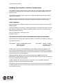
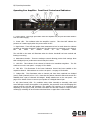
Gain settings are changed internally by simple jumper links. Four rows of pins
marked:- GAIN A, GAIN B, GAIN C and GAIN D - are situated on the input PCB
(PCB721). A jumper link sets the gain and the settings are as follows:
Link 1 & 2
Link 3 & 4
Link 4 & 5
gives
gives
gives
32dB gain
26dB gain
approx. 31dB gain = 6dBu/1.5V sensitivity into
4 ohms
NOTE: Factory setting is normally link 1 & 2 = 32dB gain.
Setting higher gain does not change the maximum available power but
changes the level of signal input to achieve maximum power. In any case,
provided that the input signal is less than 20dBu/7.7V, the built in limiter
circuit will prevent distortion within the amplifier.
The gain should be set to match the signal from the source, e.g. mixer,
controller, equaliser etc.
Power Requirements
The AQ-3 can be supplied for nominal mains voltages of 115V or 230V.
An internal link can be set to either 100V or 120V for the 115V version, and 220V or
240V for the 230V version. Normally these are set to 120V and 240V respectively.
This amplifier will only operate to its very high specification if it is installed
and operated as described in this manual.