1
PROGRAMMING MANUAL
IDM1xx Bluetooth
Hand-held Scanners
Hand-held Line
Revision History
S
Rev. No.
Released Date
Rev. A
Jan.10, 2010
First Release
Rev. A1
Mar.23, 2010
Modify UPC-E/EAN-8 expansion and UPC-A standardization.
Add “Presentation Sensitivity”.
Add “Extremely short” option to Good Read Duration.
Jun.30, 2010
Add “UPC/EAN Security Level”.
Baud Rate – Add 57.6K BPS and 115.2K BPS.
Add “Immediate” parameter for "Time Delay to Low Power Trigger" and
change the default value from 5 sections to immediate.
Hands Free Time out – Add “Disable”.
Rev. A3
Sep 23, 2010
Add “Supplement Scan Voting” in Symbology Reading Control
Add “EAN Supplement Control”
Keyboard Layout – Add “Czech (QWERTY)”, remove “Universal”, and rename
Spain (QWERTY) to Spain (Spanish QWERTY), Latin America (QWERTY) to
Spain (Latin America, QWERTY)
Add “Good Read Indicator”
Add “Scan Rate Control”
Add “‹Scanned Data› ‹Field Delimiter› ‹Quantity›” parameter selection on
Batch Data Quantity Output Format.
Rev. A4
Nov 30, 2010
Baud Rate – Cancel Baud Rate 300/600 BPS.
Rev. A5
Jan 05, 2011
Buzzer Tone Adjust – Modify No power-on beep behavior. The setting of
No power-on beep will impact both Bluetooth Scanner and Smart Cradle.
Add “Beeping Control” setting.
Reference Manual
IDM Bluetooth
Rev.A2
8014563/WE95/2012-07-25
Description
© SICK AG · Germany · All rights reserved · Subject to change without notice
2
Revision History
S
Rev. No.
Released Date
Rev. A6
Mar 04, 2011
Baud Rate – Revise 57.6K BPS and 115.2K BPS option code from 6.7. to 8.9.
Rev. A7
Mar 07, 2011
Add ”Code 39 Security Level”
Add “NAK Retry Count”
Add “ACK/NAK Transmission Indication”
Description
Introduction of IDM160 Bluetooth
Rev. A8
Jun 27, 2011
UCC/EAN-128 was renamed GS1-128.
Add new parameter selections to “ACK/NAK Transmission Indication”.
Add new parameter selections to “Serial Response Time-out”.
Add “Laser Aiming Control”
Reference Manual
IDM Bluetooth
Add “Numeric Bar Codes”
Rev. A9
Aug 02, 2011
“Paging/ Reset button” is changed from 3 seconds to 5 seconds.
Rev. A10
July 25, 2012
General Update
SICK makes no warranty of any kind with regard to this publication, including, but not limited to, the implied warranty of
merchantability and fitness for any particular purpose. SICK shall not be liable for errors contained herein or for incidental
consequential damages in connection with the furnishing, performance, or use of this publication. This publication contains
proprietary information that is protected by copyright. All rights are reserved. No part of this publication may be photocopied,
reproduced or translated into any language, in any forms, in an electronic retrieval system or otherwise, without prior written
permission of SICK.
8014563/WE95/2012-07-25
© SICK AG · Germany · All rights reserved · Subject to change without notice
3
S
Warranty
The currently released status of SICK General Terms of Delivery Factory Automation and Logistics Automation shall apply
Regulatory
FCC, CE, CNS, LP, MIC
LED Eye Safety
IEC62471-1 LED Class 1
RohS
All Bluetooth IDM devices are conform to RohS standards
Reference Manual
IDM Bluetooth
Print out this manual
If you want to print out this manual please ensure that the original size is remained and the print out is of good quality.
Otherwise the configuration codes contained in this manual may be distorted and cannot be scanned anymore.
Deutsche Version / German version
Das Handbuch ist auch in deutscher Sprache verfügbar. Es kann unter www.sick.com heruntergeladen werden.
This manual is available in German language as well. You can download it on www.sick.com.
8014563/WE95/2012-07-25
© SICK AG · Germany · All rights reserved · Subject to change without notice
4
S
Table of Contents
Getting Started
Getting Familiar with Your IDM BT
Preparation before Using
Decide Your Radio Link Mode
Using IDM BT in PAIR Mode
Using IDM BT in PICO Mode
Using IDM BT in HID Mode
Using IDM BT in SPP Mode
Out-of-range Scanning/Presentation Scanning/Paging Function
Batch Scanning (Inventory Mode)
5
7
9
10
11
13
14
16
17
Reference Manual
IDM Bluetooth
Configure Your IDM
Bar Code Programming Manual
Programming Procedures
Host Interface Selection
Symbology Reading Control
Keyboard Interface Control
Serial Interface Control
Wand/Laser Emulation Control
Operation Control
Condensed DataWizard
19
20
24
25
45
49
53
54
65
Appendix
Symbology ID Table
Keyboard Function Code Table
ASCII Input Shortcut
Link Mode Quick Set/Operation Mode Quick Set
Host Interface Quick Set
Option Codes
System Commands
How to connect IDM BT scanner with configuration software IDM Set Up Tool
Indications
8014563/WE95/2012-07-25
© SICK AG · Germany · All rights reserved · Subject to change without notice
72
73
74
75
76
77
80
81
82
5
Getting Started
S
Getting Familiar with Your IDM BT
Thank you for choosing SICK IDM Bluetooth Scanners. All IDM Bluetooth Scanners deliver reliable performance for a broad
range of market applications to unleash your productivity
Reference Manual
IDM Bluetooth
IDM140BT Series Scanner
IDM160BT Series Scanner
Status Indicator
Trigger
Tether Plate
Link Indicator
Battery Cavity
Lanyard Catch
Beeper
End Cap
Retaining Screw
Scan Window
Reset Button
IDM140BT Smart Cradle
8014563/WE95/2012-07-25
IDM160-BT Smart Cradle
Center Indicator
Host Interface Port
Side Indicators
DC Power Jack
Paging/Reset Button
Upper Indicator
USB Bus Power Switch
Lower Indicator
© SICK AG · Germany · All rights reserved · Subject to change without notice
6
Getting Started
S
IDM140BT Charging Cradle
IDM160-BT Charging Cradle
Power Indicator
Host Interface Port
Reserved
DC Power Jack
Reference Manual
IDM Bluetooth
USB Bus Power Switch
8014563/WE95/2012-07-25
© SICK AG · Germany · All rights reserved · Subject to change without notice
7
Getting Started
S
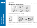
Preparation before Using
Install the Battery
Ensure the battery contacts of the battery pack are facing the charging contacts inside the battery cavity.
Slide the battery pack into the battery cavity until hearing a click sound before locking it with the end cap. The scanner
will give 4 beeps when the battery pack is installed properly if the battery pack still has power.
Secure the end cap with the screw provided.
Reference Manual
IDM Bluetooth
You can use the overlapping battery label to pull out the battery if needed.
8014563/WE95/2012-07-25
© SICK AG · Germany · All rights reserved · Subject to change without notice
8
Getting Started
Reference Manual
IDM Bluetooth
S
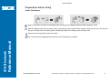
Charge the Battery
!! Please always ensure that you are using a battery with enough capacity. Otherwise it might
happen that the scanner loses its radio connection !!
Take care that the unit is placed properly inside the respective base or charging station. When unit
is not placed properly, the charging is not guaranteed.
IDM140BT:
Insert scanner vertically
IDM160BT:
First insert backside of scanner and then top part
In every case you can verify the charging status via the LED on the scanner top (see also LED
indications table inside appendix of this manual)
8014563/WE95/2012-07-25
© SICK AG · Germany · All rights reserved · Subject to change without notice
9
Getting Started
S
General Procedure
Plug the AC power plug into the appropriate AC wall socket.
Plug the DC power cord of the power supply unit into the DC power jack of the cradle. The cradle will issue the power on
beeps. The center (upper) indicator of smart cradle will give one blue blink. The power indicator of charging cradle will
turn steady blue.
Place the scanner on the cradle. The status indicator of scanner will turn steady red if the battery is not fully charged.
When the battery is fully charged, the status indicator of scanner will flash green at regular interval.
Please charge the new battery pack for 8 hours prior to the first use.
Reference Manual
IDM Bluetooth
Use USB Bus Power
If USB 3.0 is available in your host device, both battery charging and regular operation can be supported by the USB
Bus Power without using external power supply.
If you want to use this feature, please slide the USB bus power switch to “ON”. Then connect the cradle and host device
via USB cable.
8014563/WE95/2012-07-25
© SICK AG · Germany · All rights reserved · Subject to change without notice
10
Getting Started
S
Communication Cables
Both the IDM140BT and the IDM160BT offer PS/2, USB and RS232 interface.
USB
The cable inlet of both IDM140BT and IDM160BT base station is on the bottom side.
Please ensure that the cable is correctly pushed into the RJ inlet of the base station to secure data
transmission to the host
Reference Manual
IDM Bluetooth
IDM140BT base station
IDM160BT base station:
Push down plastic spring and insert cable
Correct
8014563/WE95/2012-07-25
Not Correct
© SICK AG · Germany · All rights reserved · Subject to change without notice
11
Getting Started
S
Decide Your Radio Link Mode
The IDM Bluetooth image scanner provides several radio link modes to communicate with most host devices. When the
Bluetooth-enabled host device is not available, it can work with the smart cradle in PAIR mode (one to one connection) or
PICO mode (multiple connections) to provide a plug-and-play cordless migration of your existing non-Bluetooth-enabled IT
assets. Moreover, you are also able to use the scanner to work with Bluetooth-enabled host devices via SPP master/slave
modes and HID mode.
After losing the radio link, the scanner is capable of resuming the radio connection automatically while it returns to the
communication coverage. But please note that this feature is not available in SPP slave mode. If you would like to change
the radio link mode, you have to scan the “Uninstall” command to revert the scanner to uninstall state.
PAIR Mode – 1 scanner connected to one cradle
Reference Manual
IDM Bluetooth
If the Bluetooth device is not available in your existing system, this is the simplest plug-and-play solution. In this mode, one
scanner can only work with one smart cradle. The smart cradle not only provides the Bluetooth radio link with the scanner,
but also offers the legacy cabled interfaces to the host device, including USB HID, USB COM, PS/2(DOS/V) Keyboard
Wedge and RS232 Serial.
PICO Mode – up to 7 scanners connected to one cradle
For the requirement of multiple connections, up to 7 scanners can be connected to one smart cradle concurrently. If you
would like to un-pair all paired scanners and smart cradle, you can simply press and hold the paging/reset button of the
smart cradle for over 5 seconds. If you just want to un-pair part of the paired scanners, please take those paired scanners to
scan the “Uninstall” command one by one.
HID Mode –HID communication directly to Bluetooth host without cradle
Through the most helpful HID service, the scanner can work like a Bluetooth keyboard. In this mode, the scanner is
discoverable by the radio connection request issued by a remote host device. For security purpose, you will be requested to
input the PIN Code to establish the Bluetooth connection in most time.
SPP Master/Slave Mode– Serial communication directly to Bluetooth host without cradle
Through the standard SPP service, the scanner can work like a serial input device. In SPP master mode, the scanner
initiates the radio connection request to a remote slave device. In SPP slave mode, the scanner is discoverable by the radio
connection request issued by a remote master device.
8014563/WE95/2012-07-25
© SICK AG · Germany · All rights reserved · Subject to change without notice
12
Getting Started
S
Using IDM BT in PAIR Mode
Ensure the battery is fully charged. You may refer to the section of Preparations before Using for details.
Please choose your desired interface cable, then plug it into the host interface port of the smart cradle and connect it to
the host device.
USB
PS/2
RS232
Turn on the power of your host device.
Please note that the scanner has been pre-paired already, if the scanner is shipped together with the smart cradle. You
will see the link indicator of scanner gives 1 blue blink per 2.5 seconds and the middle indicator of smart cradle turns
steady blue. If the scanner and smart cradle just give alternating red and green blinks (in “Uninstall” state), please
follow steps 5-6 to establish the connection between the scanner and the smart cradle.
Reference Manual
IDM Bluetooth
Scan “PAIR mode” command. The status indicator of scanner will turn steady red.
Uninstall
PAIR Mode
Place the scanner on the smart cradle, then you will hear one short beep to indicate the pairing process is activated. The
scanner will give continuous short clicks and the link indicator of scanner will flash blue quickly during the pairing process.
When you hear 4 beeps in ascending tone, the pairing process is completed. You will see the link indicator of scanner
giving 1 blue blink per 2.5 seconds and the center or upper indicator of the smart cradle turning steady blue.
If the scanner pairing process failed or it’s not placed on the smart cradle within 20 seconds, you will hear 2 “Di-do Di-do”
beeps to indicate pair failure, the scanner will return to uninstall state automatically.
Scan the corresponding host interface quick set command to complete the installation.
The default host interface of smart cradle is preset to USB HID. If you want to set the host interface to USB COM, you have to
install the USB virtual COM driver (available on www.sick.com) into your host device before using the scanner. General
selection of host interface can be made via chapter “Host Interface Selection”.
8014563/WE95/2012-07-25
© SICK AG · Germany · All rights reserved · Subject to change without notice
13
Getting Started
S
Using IDM BT in PICO Mode
Ensure the battery is fully charged and choose your desired interface cable, then plug it into the host interface port of the
smart cradle and connect it to the host device.
USB
PS/2
RS232
Turn on the power of your host device.
Reference Manual
IDM Bluetooth
Ensure the side (IDM140BT cradle) or lower indicator (IDM160BT cradle) of the smart cradle give alternative red and
green blinks (in “Uninstall” state). If the smart cradle is paired with other scanners, you can press and hold the
paging/reset button for over 5 seconds to un-pair all paired scanners. Then smart cradle will return to uninstall state
automatically.
Prepare the scanners you desire to pair with smart cradle. Ensure the status indicator of each scanner give alternative
red and green blinks (in “Uninstall” state). If the scanner is not in uninstall state, please scan the “Uninstall” command to
un-pair the scanner. Then scan the “PICO mode” command, and the status indicator of scanner will turn steady red.
Uninstall
PICO Mode
Place the scanner on the smart cradle, then you will hear one short beep to indicate the pairing process is activated. The
scanner will give continuous short clicks and the link indicator of scanner will flash blue quickly during the pairing process.
When you hear 4 beeps in ascending tone, the pairing process is completed. You will see the link indicator of scanner
giving 1 blue blink per 2.5 seconds, the center or upper indicator of the smart cradle turning steady blue and its side
indicators turning steady green. If the scanner pairing process failed or it’s not placed on the smart cradle within 20
seconds, you will hear 2 “Di-do Di-do” beeps to indicate pair failure, the scanner will return to uninstall state automatically.
Scan the corresponding host interface quick set command to complete the installation.
Please follow the same procedures to pair the other scanners with the smart cradle.
For user’s convenience, the smart cradle will automatically assign the ID numbers to each scanner. After completed all
pairing processes, you can scan the “System Information” command to check the assigned ID number of each scanner.
8014563/WE95/2012-07-25
© SICK AG · Germany · All rights reserved · Subject to change without notice
14
Getting Started
S
Clone Function
For the user’s convenience, the clone function will help you to clone the host interface related parameters (please refer to
following table for details) from one of the paired scanners to the rest of paired scanners under PICO mode. You can use
one of the paired scanners to set the host interface related parameters first and then scan “Save Configuration” command.
After that, please take the other paired scanners to scan “Clone” command one by one to clone the host interface related
parameters.
Please ensure to keep those paired scanners in connected status when you use the “Clone” function. Because the host
interfaces related parameters can’t be cloned to the paired scanner in disconnected status.
Save Configuration
Clone
The below host interface related parameters will be impacted by clone function:
Reference Manual
IDM Bluetooth
Data Transmission Parameter
Serial Interface Control
Field Delimiter
Handshaking Protocol
Data Transmission Format
Intermessage Delay
Host Interface Control
Host interface Selection
Keyboard Interface Control
Interfunction Delay
Intercharacter Delay
Baud Rate
Keyboard Layout
Data Frame
Intermessage Delay
Time Out Control
Interfunction Delay
Wand Emulation Control
Intercharacter Delay
Output Polarity
Caps Lock Control
Initial Signal State
Caps Lock Release Control
Margin Time
Function Key Emulation
Module Time
Key Pad Emulation
Narrow/Wide Ratio
Upper/Lower Case
Code39 Emulation
8014563/WE95/2012-07-25
© SICK AG · Germany · All rights reserved · Subject to change without notice
15
Getting Started
S
Using IDM BT in HID Mode
Ensure the battery is fully charged. Power on the scanner within radio range and ensure the status indicator of scanner
gives alternating red and green blinks (in “Uninstall” state). If the scanner is not in uninstall state, please scan the
“Uninstall” command first. Then scan the “HID Mode” command, and the link indicator of scanner will give 3 blue blinks
per 2 seconds.
Uninstall
HID Mode
Execute the Bluetooth Discovery procedure to find all available Bluetooth devices in your remote host. You will see
‘’IDMxxxBT-xxxx’’ is shown in the list if the scanner is successfully discovered already.
Double click the “IDMxxxBT-xxxx” in the discovered Bluetooth device list. If the PIN Code or Passkey is requested for
security connection, please enter “00000000” (default setting). You will see “Keyboard on IDMxxxBT-xxxx”, and double
click this HID service to establish the connection between the scanner and the remote host device.
Reference Manual
IDM Bluetooth
The scanner will give 4 beeps in ascending tone to indicate the radio is connected. At the same time, the link indicator of
scanner will give 1 blue blink per 2.5 seconds to indicate the scanner is in radio-connected state.
Please note that if the scanner is not connected to the host device within 1 minute after scanning the “HID Mode”
command, the scanner will go to sleep automatically. You just need to press the trigger to wake up the scanner to
continue the installation.
1. The installation procedures vary on different remote host devices, operation systems and the Bluetooth software driver.
Please consult your professional IT consultant to obtain necessary support if any problem has been encountered during
the installation processes.
2. While using HID mode, beware of potential error in the data transmitted at the same time when radio link quality is poor.
You are suggested to use the scanner under the communication coverage all the times.
8014563/WE95/2012-07-25
© SICK AG · Germany · All rights reserved · Subject to change without notice
16
Getting Started
S
Using IDM BT in SPP Mode
Establish SPP Master Connection
Ensure the battery is fully charged. Please go to the folder of “Hardware” located in Bluetooth Advanced Setting of the
remote host device to check its device MAC address. Then prepare a 12-character Code 128 barcode of the remote host
device MAC address, or follow the step 4 to input MAC address by scanning 12 option codes.
Ensure a virtual COM port is available in your remote host for connecting the scanner. If not, please go to the folder of
“Local Services” located in Bluetooth Advanced Setting. Click the “Add Serial Services” to add one more Bluetooth
COM port.
Power on the scanner within radio range and ensure the status indicator of scanner gives alternating red and green
blinks (in “Uninstall” state). If the scanner is not in uninstall state, please scan the “Uninstall” command first. Then scan
the “SPP Master Mode” command, and the status indicator of scanner will turn steady red.
Reference Manual
IDM Bluetooth
Uninstall
SPP Master Mode
Scan a 12-character MAC address barcode, or scan 12 option codes and “FIN” command to confirm your inputs. The
scanner will give continuous short clicks and the link indicator of the scanner will flash blue quickly during the radio
connecting process. If the PIN Code or Passkey is requested for security connection, please enter “00000000” (default
setting).
The scanner will give 4 beeps in ascending tone to indicate the radio is connected. At the same time, the link indicator of
scanner will give 1 blue blink per 2.5 seconds to indicate the scanner is in radio-connected state.
Please note that if the scanner failed to connect to the host device within 30 seconds, the link indicator will give 3 blue
blinks per 2 seconds. But the scanner is still continuing to discover the host device for another 30 seconds before go to
sleep. In the interim, you still can scan “Uninstall” command to revert the scanner to uninstall state. If the scanner goes to
sleep already, you just need to press the trigger to wake up the scanner to continue the installation.
The installation procedures vary on different remote host devices, operating systems and the Bluetooth software driver.
Please consult your professional IT consultant to obtain necessary support if any problem has been encountered during the
installation processes.
8014563/WE95/2012-07-25
© SICK AG · Germany · All rights reserved · Subject to change without notice
17
Getting Started
S
Establish SPP Slave Connection
Ensure the battery is fully charged and a virtual COM port is available in your remote host for connecting the scanner. If
not, please go to the folder of “Client Applications” located in Bluetooth Advanced Setting. Click the “Add COM Port” to
add one more Bluetooth COM port.
Power on the scanner within radio range and ensure the status indicator of scanner gives alternating red and green
blinks (in “Uninstall” state). If the scanner is not in uninstall state, please scan the “Uninstall” command first. Then scan
the “SPP Slave Mode” command, and the link indicator of scanner will give 3 blue blinks per 2 seconds.
Uninstall
SPP Slave Mode
Reference Manual
IDM Bluetooth
Execute the Bluetooth Discovery procedure to find all available Bluetooth device list in your remote host. You will see
‘’ IDMxxxBT-xxxx’’ is shown in the list if the scanner is successfully discovered already.
Double click the “IDMxxxBT-xxxx” on the discovered Bluetooth devices. If the PIN Code or Passkey is requested for
security connection, please enter “00000000” (default setting). You will see “Serial Port on IDMxxxBT-xxxx”, and double
click this SPP service to establish the connection between the scanner and the remote host device.
The scanner will give 4 beeps in ascending tone to indicate the radio is connected. At the same time, the link indicator of
scanner will give 1 blue blink per 2.5 seconds to indicate the scanner is in radio-connected state.
Please note that if the scanner is not connected to the host device within 1 minute, the scanner will go to sleep. You can
press the trigger to wake up the scanner to continue the installation.
The installation procedures vary on different remote host devices, operating systems and the Bluetooth software drivers.
Please consult your professional IT consultant to obtain necessary support if any problem has been encountered during the
installation processes.
8014563/WE95/2012-07-25
© SICK AG · Germany · All rights reserved · Subject to change without notice
18
Getting Started
S
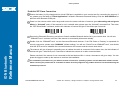
Out-of-range Scanning
When the radio is connected between the scanner and the remote host device, the scanner will transmit each scanned data
right after scanning the barcode. However, the scanner is preset for unable to scan any barcode data when it loses the radio
connection with the remote host device.
If you enable the out-of-range scanning function, the scanner is able to continue scanning barcode data while it is out of
working range. All scanned data will be temporarily stored into the memory buffer until radio link resumed.
Enable Out-of-range Scannning
Disable Out-of-range Scanning ◆
In case of the scanner is out of working range, you will hear 4 beeps in descending tone to indicate the radio connection lost.
The link indicator of scanner will give 3 blue blinks per 2 seconds. Once the scanner is back to working range, you will hear 4
beeps in ascending tone to indicate the radio connection rebuilt and the scanner will give 1 blue blink per 2.5 seconds. At the
same time, all stored scanned data will be transmitted automatically right after the radio link is resumed.
Reference Manual
IDM Bluetooth
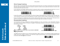
Presentation Scanning
The Presentation Scanning is designed for hand-free applications for user’s convenience. If the “Presentation Scanning
Auto-sense” function is enabled, the scanner is capable of automatically switching to presentation mode when you place it
onto the Stand or cradle.
Enable Presentation Scanning Auto-sense
Presentation scanning on cradle is only available for IDM140BT.
Disable Presentation Scanning Auto-sense ◆
Paging Function
The paging function is helpful for you to locate the paired smart cradle or scanner. If you would like to page the paired smart
cradle, you can scan “Paging” command. If you would like to page the paired scanner, you can press the paging/rest button
of the smart cradle no longer than 5 seconds.
Paging
8014563/WE95/2012-07-25
© SICK AG · Germany · All rights reserved · Subject to change without notice
19
Getting Started
S
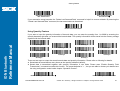
Batch Scanning (Inventory Mode)
Thanks to the specially designed Batch Scanning function, the scanner is capable of storing the barcode data up to 20,000
EAN-13 labels. It is an ideal cost-saving solution for inventory applications.
Once you scan the “Enter Batch Scanning” command to activate this function, all scanned barcode data will be stored into
the memory storage, and the status indicator of scanner will give green blink at regular interval during batch scanning. You
can scan and store the barcode data till the memory storage is full. If the storage is full, you will hear 2 long beeps and the
status indicator will give 2 red blinks to indicate out of storage. To terminate the batch scanning, please scan the “Exit Batch
Scanning” command.
Enter Batch Scanning
Exit Batching Scanning
How to Transmit Stored Data
Reference Manual
IDM Bluetooth
The scanner is preset so you need to scan the “Transmit Stored Data” command to transmit all stored data. During the
transmission process, the scanner will give continuous short clicks and blue blinks. Then the scanner will give two short
beeps after data transmission is completed.
Transmit Stored Data
But you are also able to set the scanner to transmit the stored data by placing the scanner onto the cradle.
Transmit Stored Data by Scanning
Barcode Command ◆
Transmit Stored Data by Scanning Barcode
or Placing Scanner onto Cradle
Transmit Stored Data by
Placing Scanner onto Cradle
The scanner is preset to keep all the stored data until you scan the “Clear All Stored Data” command. But you are also able
to change the setting to “Auto Delete Stored Data after Transmission”.
Clear All Stored Data
8014563/WE95/2012-07-25
© SICK AG · Germany · All rights reserved · Subject to change without notice
20
Getting Started
S
Auto Delete Stored Data
after Transmission
Keep Stored Data after
Transmission ◆
If you scanned a wrong barcode, the “Delete Last Scanned Data’’ command is helpful to recover mistake. By scanning the
‘’Delete Last Scanned Data’’ command, the last stored data can be deleted.
Delete Last Scanned Data
Using Quantity Feature
Reference Manual
IDM Bluetooth
If you want to input the quantity information of barcode data, you can enter the quantity from 1 to 9999 by scanning the
quantity barcodes right after you scanned the barcode data. The quantity information will be stored into the memory storage
together with the barcode data.
Quantity 0
Quantity 5
Quantity 3
Quantity 1
Quantity 8
Quantity 6
Quantity 4
Quantity 2
Quantity 9
Quantity 7
There are two ways to output the stored barcode data and quantity information. Please refer to following for details:
Stored data is transmitted as many times as the quantity indicated (default).
Stored data is transmitted together with quantity information in two fields. Please scan “Enable Quantity Field
Transmission” command to enable this function. The preset delimiter is “,
,“, but you are able to choose your desired one
via using configuration codes inside chapter “Operation Control”.
Disable Quantity Field Transmission ◆
8014563/WE95/2012-07-25
Enable Quantity Field Transmission
© SICK AG · Germany · All rights reserved · Subject to change without notice
21
Configure Your IDM BT
S
Bar Code Programming Manual
The IDM BT bar code commands are specially designed
Proprietary bar code labels which allow you to set the IDM
BT internal programming parameters. There are System
Command, Family Code and Option Code for
programming purpose.
Reference Manual
IDM Bluetooth
Each programmable family and bar code command label is
listed on the same page with major system commands. The
detailed explanations and special programming flowchart are
printed on facing or following pages. You can read the
explanation and set the IDM BT concurrently.
A supplemental bar code command menu incorporates the
bar code command labels of System Command and Option
Code. As you set the IDM, open the bar code command
menu to find the option code page. You may scan the desired
family code and option code to set IDM. If you want to
change the programming family for multiple settings, you
need only turn over the programming page to find next
desired programming family.
8014563/WE95/2012-07-25
System Command
The System Command is the highest level bar code
command which directs IDM BT to perform immediate
operations, such as entering programming mode
(PROGRAM), exiting programming mode (EXIT), listing
system information (SYSLIST), recovering to factory
preset configurations (M_DEFAULT), and so on. Please
note that all system commands will take a few seconds to
complete the operations. User must wait for the
completion beeps before scanning another bar code.
Family Code
The Family Code is scanned to select the user desired
programming family. IDM BT has already provided more
than one hundred programming families to meet any
specific requirements.
Option Code
The Option Codes is a set of bar code commands
represented by “0–9”, “A–F” and finishing selection (FIN).
For most setting, you must select at least one option code
following the family code selection to set the desired
parameter for the selected programming family.
© SICK AG · Germany · All rights reserved · Subject to change without notice
22
Configure Your IDM BT
S
Programming Procedures
Reference Manual
IDM Bluetooth
As you scan the bar code command to select the desired
parameters, information about the final selected parameters
represented by the bar code commands are stored in the
IDM’s internal Flash Memory ASIC or non-volatile memory.
If you turn off the unit, the Flash Memory ASIC or
non-volatile memory retains all programming options. You
need not re-program the IDM BT if you want to keep the
existing configurations in the next power on.
The programming procedures of IDM BT are designed as
simple as possible for ease of setting. Most programming
families take the Single Scan Selection programming
procedure. But several programming families have more
complex and flexible programmable options, and you must
take Multiple Scans Selection, Cycling Scan Selection
or Dual Level Selection to complete their programming
procedures. Each kind of programming procedure is listed
in the following pages for your reference. Please give
careful attention to become familiar with each programming
procedure.
If the programming family must take multiple scans
selection, cycling scan selection, or dual level selection
procedures, the family of the programming menu will be
marked with the matched representing symbol of
Programming Category (P.C.) in bold font listed in the
following table. You can easily find the bold mark in the
programming menu, and refer to their flowcharts for details.
Before setting the IDM, please also refer to the “Beeping
Indications” listed in Appendix to understand the details of
programming beeping indications. It will be very helpful for
you to know the existing status while you are programming
the IDM.
Conventions of Programming Menu
Conventions
Descriptions
Factory Default Value
P.C.
Programming Category
SS : Single scan selection
MS : Multiple scans selection
CS : Cycling scan selection
DS : Dual level scan selection
8014563/WE95/2012-07-25
(
)
Necessary Option Code
[
]
Selectable Option Code
© SICK AG · Germany · All rights reserved · Subject to change without notice
23
Configure Your IDM BT
S
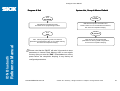
Program & End
System List, Group & Master Default
Scan
“PROGRAM”
Scan
“SYSLIST”
IDM will enter programming mode,
and inhibit all non-programming functions.
revision number to host via selected host interface,
IDM will list the product information and
then issue the completion beeping.
Scan
“M_DEFAULT”
Scan
“END”
IDM
will exit programming mode, and store all
Reference Manual
IDM Bluetooth
parameters in Flash Memory ASIC or non-volatile memory,
then issue the completion beeping.
IDM will recover all programmable
parameters into factory preset configurations,
then issue the completion beeping.
Please note that the IDM BT will take 3-4 seconds to store
parameters in internal Flash Memory ASIC or non-volatile
memory after you scan the “END”. Please don’t turn off the
power before the completion beeping. It may destroy all
configured parameters.
8014563/WE95/2012-07-25
© SICK AG · Germany · All rights reserved · Subject to change without notice
24
Configure Your IDM BT
S
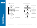
Single scan selection
Scan
“PROGRAM”
Multiple scans selection
Enter programming mode.
Select one of desired
Scan
One of Family Codes
programming families.
Select one option code of
Scan
One of Option Codes
Scan
“PROGRAM”
desired parameter.
Enter programming mode.
Select one of desired
Scan
One of Family Codes
programming families.
1. Select one or several
Scan One or
Several Option Codes
option codes to select
desired parameters.
2. If it’s necessary, scan
“FIN” to terminate
Reference Manual
IDM Bluetooth
Yes
Want to select another
Repeat
Selection
programming family?
Yes
Repeat
Selection
option code selection.
Want to select another
No
No
Scan
“END”
8014563/WE95/2012-07-25
Exit programming mode.
Scan
“END”
programming family?
Exit programming mode.
© SICK AG · Germany · All rights reserved · Subject to change without notice
25
Configure Your IDM BT
S
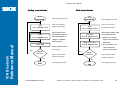
Cycling scan selection
Dual level selection
Scan
“PROGRAM”
Scan
“PROGRAM”
Enter programming mode.
Select one of desired
Scan
One of Family Codes
Scan
One of Family Codes
programming families.
Cycling select one or
Scan
One of Option Codes
several option codes of
desired parameters as
Reference Manual
IDM Bluetooth
(2nd) Scan One or
Several Option Codes
Scan “FIN”
8014563/WE95/2012-07-25
1. Select one or several
parameters.
2. If it’s necessary, scan
“FIN” to terminate
(If necessary)
option code selection.
Yes
Want to select another
No
“END”
of desired parameters.
Finish cycling selection.
Repeat
Selection
programming family?
Scan
programming families.
option codes of desired
scans selection.
Repeat
Selection
Select one of desired
Select several option codes
(1st) Scan
Several Option Codes
“Single” or “Multiple”
Yes
Enter programming mode.
Want to select another
programming family?
No
Exit programming mode.
Scan
“END”
Exit programming mode.
© SICK AG · Germany · All rights reserved · Subject to change without notice
26
Configure Your IDM BT
S
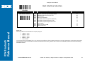
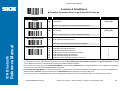
Host Interface Selection
Reference Manual
IDM Bluetooth
PROGRAM
Family Code Selection
P.C
Host Interface Selection
MS
MS
MS
MS
MS
MS
MS
MS
MS
MS
Parameter Selection
IBM PS/2, 25-30 series keyboard wedge interface
Standard/TTL RS-232 peer-to-peer serial
Wand emulation
USB Com Port Emulation
PS/2 (DOS/V) direct link (keyboard replacement)
PS/2 (DOS/V) keyboard wedge turbo mode
PS/2 (DOS/V) keyboard wedge standard mode
Laser emulation
USB HID standard mode USB HID turbo mode
Option Code
02
06
08
09
10
13
14
17
18
19
Please note:
When using USB mode, field disturbances in frequency ranges of
• 16 MHz +/- 1 MHz
• 32 MHz +/- 1 MHz
• 48 MHz +/- 1 MHz
• 64 MHz +/- 1 MHz
• 120 to 150 MHz
can reduce the immunity of IDM160BT. This is only valid while using USB mode. After a possible disturbance, the scanner automatically re-connects with its base station.
Codes that were scanned in the meantime are stored in the internal scanner memory. After the radio connection is re-established, buffered codes will be automatically
transmitted to the host.
8014563/WE95/2012-07-25
© SICK AG · Germany · All rights reserved · Subject to change without notice
27
Configure Your IDM BT
S
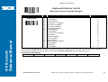
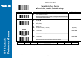
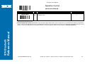
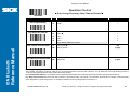
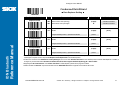
Symbology Reading Control
♦ User Defined Symbol ID ♦
Reference Manual
IDM Bluetooth
PROGRAM
Family Code Selection
P.C
Symbol ID : 1 character
DS
Parameter Selection
Code 128 (default=B)
GS1-128 (default=C)
UPC-A (default=A)
EAN-13 (default=F)
Codabar/NW-7 (default=D)
Code 39/Code 32 (default=G)
Code 93 (default=H)
Standard/Industrial 2 of 5 (default=I)
Interleaved 2 of 5 (default=J)
Matrix 2 of 5 (default=K)
China Postal Code (default=L)
German Postal Code (default=M)
IATA (default=O)
Code 11 (default=P)
MSI/Plessey (default=R)
UK/Plessey (default=S)
Telepen (default=T)
GS1 DataBar (default=X)
UPC-E (default=E)
EAN-8 (default=N)
Trioptic Code 39 (Default=W)
UCC Coupon Extended Code (Default=Z)
PDF417/Micro PDF417 (default=V)
Codablock F (default=Y)
Korea Post Code (default =a)
Option Code
2nd Option Code
00
01
02
03
04
05
06
07
08
09
10
11
12
13
14
15
16
17
18
19
20
21
22
23
26
(1 character)
(1 character)
(1 character)
(1 character)
(1 character)
(1 character)
(1 character)
(1 character)
(1 character)
(1 character)
(1 character)
(1 character)
(1 character)
(1 character)
(1 character)
(1 character)
(1 character)
(1 character)
(1 character)
(1 character)
(1 character)
(1 character)
(1 character)
(1 character)
(1 character)
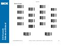
If your application requires user defined symbology IDs you are able to configure it.
8014563/WE95/2012-07-25
© SICK AG · Germany · All rights reserved · Subject to change without notice
28
Configure Your IDM BT
S
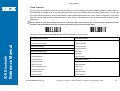
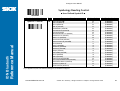
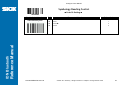
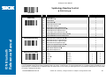
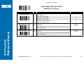
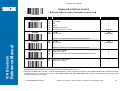
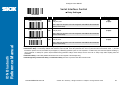
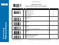
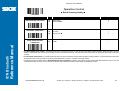
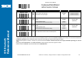
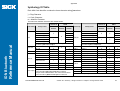
Symbology Reading Control
♦ Symbology ID Transmission ♦
Family Code Selection
P.C
Symbology ID Transmission
SS
SS
SS
SS
SS
SS
SS
Parameter Selection
Disable symbology ID transmission Enable prefix user defined symbology ID transmission
Enable suffix user defined symbology ID transmission
Enable both prefix and suffix user defined symbology ID transmission
Enable prefix AIM symbology ID transmission
Enable suffix AIM symbology ID transmission
Enable both prefix and suffix AIM symbology ID transmission
Option Code
0
1
2
3
4
5
6
Reference Manual
IDM Bluetooth
PROGRAM
8014563/WE95/2012-07-25
© SICK AG · Germany · All rights reserved · Subject to change without notice
29
Configure Your IDM BT
S
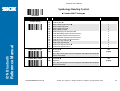
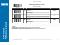
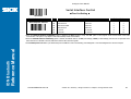
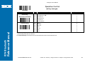
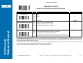
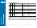
Symbology Reading Control
♦ Readable Bar Code Setting ♦
Reference Manual
IDM Bluetooth
PROGRAM
Family Code Selection
P.C
Readable Symbology Setting
SS
CS
CS
CS
CS
CS
CS
CS
CS
CS
CS
CS
CS
CS
CS
CS
CS
CS
CS
CS
CS
CS
CS
CS
Parameter Selection
Auto Code 128 *
UPC-A *
UPC-E *
EAN-13 *
EAN-8 *
Codabar/NW-7 *
Code 39 *
Trioptic Code 39
Standard/Industrial 2 of 5
Matrix 2 of 5
Interleaved 2 of 5 *
China Postal Code
German Postal Code
Code 93 *
Code 11
MSI/Plessey
UK/Plessey
Telepen
GS1 DataBar (RSS-14) *
IATA
PDF417/Micro PDF417
Codablock F
Korea Post Code
Option Code
00
01
02
03
04
05
06
07
47
08
38
48
58
68
09
10
11
12
13
14
15
17
18
21
If your application is known, you may select those known symbologies only to increase the reading speed and decrease the possibility of reading error. Furthermore, to add
the “Symbology ID” into the transmitted data is also helpful to identify the specific symbology.
Above symbologies marketed with * are enable as default. When you select “Auto”, the scanner only read those symbologies marked with *
When you set the minimum and maximum length of each symbology, please note the data length of scanned bar code doesn’t include star/stop characters.
8014563/WE95/2012-07-25
© SICK AG · Germany · All rights reserved · Subject to change without notice
30
Configure Your IDM BT
S
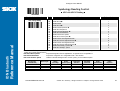
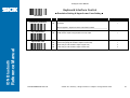
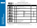
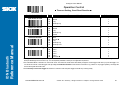
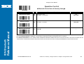
Symbology Reading Control
♦ Code 39/Code 32 Setting ♦
Reference Manual
IDM Bluetooth
PROGRAM
Family Code Selection
P.C
Parameter Selection
Option Code
Code 39 Family Setting
SS
SS
SS
SS
SS
SS
SS
SS
SS
SS
SS
SS
SS
SS
SS
Disable Code 39
Enable Code 39
Select Standard Code 39 as primary format Select Full ASCII Code 39 as primary format
Select Code 32 (PARAF, Italian Pharmaceutical) as primary format
Disable start/stop symbol transmission Enable start/stop symbol transmission
Disable Code 32 leading A transmission Enable Code 32 leading A transmission
Disable MOD 43 check digit verification Enable MOD 43 check digit verification
Disable check digit transmission Enable check digit transmission
Disable Code 39 buffering Enable Code 39 buffering
0
1
2
3
4
5
6
7
8
9
A
B
C
D
E
Trioptic Code 39 Setting
SS
SS
Disable Trioptic Code 39 Enable Trioptic Code 39
0
1
Code 39 Min. Length
SS
MS
Default (01) 01-Maximum
FIN
(2 digits)
Scan 2 digits from the option code chart in Appendix, then IDM BT will terminate this
selection automatically.
Code 39 Max. Length
SS
MS
Default (98) 98-Minimum
FIN
(2 digits)
Scan 2 digits from the option code chart in Appendix, then IDMBT will terminate this
selection automatically.
Trioptic Code 39 and Code 39 Full ASCII cannot be enabled simultaneously.
8014563/WE95/2012-07-25
© SICK AG · Germany · All rights reserved · Subject to change without notice
31
Configure Your IDM BT
S
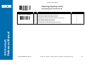
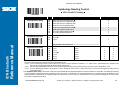
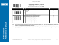
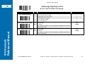
Symbology Reading Control
♦ Code 39 Setting ♦
Family Code Selection
P.C
Code 39 Security Level
SS
SS
SS
SS
Parameter Selection
Level 0
Level 1
Level 2 Level 3
Option Code
0
1
2
3
Reference Manual
IDM Bluetooth
PROGRAM
8014563/WE95/2012-07-25
© SICK AG · Germany · All rights reserved · Subject to change without notice
32
Configure Your IDM BT
S
Symbology Reading Control
♦ Codabar/NW-7 Setting ♦
Reference Manual
IDM Bluetooth
PROGRAM
Family Code Selection
P.C
Parameter Selection
Codabar Setting
SS
SS
SS
SS
SS
SS
SS
SS
SS
SS
SS
SS
SS
SS
SS
Disable Codabar
Enable Codabar Select Codabar standard format Select Codabar ABC format
Select Codabar CLSI format
Select Codabar CX format
Disable start/stop symbol transmission Enable ABCD/ABCD start/stop symbol transmission
Enable abcd/abcd start/stop symbol transmission
Enable ABCD/TN*E start/stop symbol transmission
Enable abcd/tn*e start/stop symbol transmission
Disable check digit verification Enable check digit verification
Disable check digit transmission Enable check digit transmission
Codabar Min. Length
SS
MS
Default (04) 01-Maximum
Option Code
0
1
2
3
4
5
6
7
8
9
A
B
C
D
E
FIN
(2 digits)
Scan 2 digits from the option code chart in Appendix, then IDM BT will terminate this
selection automatically.
Codabar Max. Length
SS
MS
Default (98) 98-Minimum
FIN
(2 digits)
Scan 2 digits from the option code chart in Appendix, then IDM BT will terminate this
selection automatically.
8014563/WE95/2012-07-25
© SICK AG · Germany · All rights reserved · Subject to change without notice
33
Configure Your IDM BT
S
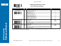
Symbology Reading Control
♦ UPC-A & UPC-E Setting ♦
Reference Manual
IDM Bluetooth
PROGRAM
Family Code Selection
P.C
UPC Family Setting
SS
SS
SS
SS
SS
SS
SS
SS
SS
SS
SS
SS
SS
SS
SS
SS
Parameter Selection
Option Code
0
1
2
3
4
5
6
7
8
9
A
B
C
D
E
F
Disable UPC-A
Enable UPC-A Disable UPC-E
Enable UPC-E Disable UPC-E expansion Enable UPC-E expansion
Disable UPC standardization Enable UPC standardization
Disable UPC numeric system
Enable UPC numeric system Disable UPC-A check digit transmission
Enable UPC-A check digit transmission Disable UPC-E check digit transmission
Enable UPC-E check digit transmission Disable UPC “leading 1” portion Enable UPC “leading 1” portion
When enable UPC-E expansion, the UPC-E decoded data will be converted to UPC-A format and affected by related setting, such as UPC standardization, UPC numeric
system, UPC-A check digit transmission.
UPC-E & EAN-8 Expansion
: Expand the 8-digit UPC-E and 8-digit ENA-8 to 12-digit UPC-A and 13-digit EAN-13.
UPC-A/E Standardization
: Expand the 12-digit UPC-A to 13-digit EAN-13 with 1 zero insertion.
UPC Lead 1 Numeric System
: Enable to read UPC leading with the 1 numeric system, you must enable this option.
WPC Selection
(UPC/EAN/CAN)
UPC-A
UPC-E
EAN-13
EAN-8
Basic Length
Disable
Check Digit
Disable
Numeric System
With 2-digit
Addendum
With 5-digit
Addendum
Enable
Standardization
Enable
Expansion
12
8
13
8
-1
-1
-1
-1
-1
-1
NC
NC
+2
+2
+2
+2
+5
+5
+5
+5
+1
+1
NC
NC
0
+4
0
+5
8014563/WE95/2012-07-25
© SICK AG · Germany · All rights reserved · Subject to change without notice
34
Configure Your IDM BT
S
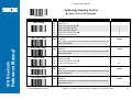
Symbology Reading Control
♦ UPC-A & UPC-E Setting ♦
PROGRAM
Family Code Selection
P.C
UPC Supplement Setting
SS
SS
SS
SS
SS
SS
SS
SS
Select UPC without supplement digits Select UPC with only 2 supplement digits
Select UPC with only 5 supplement digits
Select UPC with 2/5 supplement digits
Disable force supplement digits output Enable force supplement digits output
UPC Family Addenda Separator Off UPC Family Addenda Separator On
0
1
2
3
4
5
6
7
UPC/EAN Security Level
SS
SS
Level 0
Level 1 Level 2
0
1
Reference Manual
IDM Bluetooth
SS
Parameter Selection
Option Code
2
Only available for UPC-A & EAN-13
Supplement Scan Voting
SS
SS
SS
SS
SS
SS
SS
None
Level 1
Level 2
Level 3 Level 4
Level 5
Level 6
Level 7
Level 8
Level 9
Level 10
Level 11
Level 12
Level 13
0
1
2
3
4
5
6
7
8
9
A
B
C
D
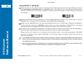
UPC/EAN Security Level
The scanner offers three levels of decode security for UPC/EAN bar codes:
Level 0: If you are experiencing misread of poorly-printed or out-of-spec. bar codes, especially in characters 1, 2, 7, and 8 in level 1, please select level 0. Selection of this
security level may significantly impair the decoding ability of the scanner.
Level 1: This is the default setting which allows the scanner to operate fastest, while providing sufficient security in decoding “in-spec” UPC/EAN bar codes.
Level 2: If you are experiencing misread of poorly-printed, soiled or damage bar codes in level 1, please select level 2. This is the most aggressive setting and may
increase the misread.
The Supplement Scan Voting is the number of times the same UPC/EAN with 2/5 supplement digits has to be decoded before it is transmitted. It is helpful when decoding
a mix of UPC/EAN symbols with and without supplement digits. This function is effective when you select UPC/EAN with only 2 supplement digits, UPC/EAN with only 5
supplement digits or UPC/EAN with 2/5 supplement digits. The default value is Level 3. When you select higher level, it may impact the reading speed on poorly-printed,
low contrast or damage barcode labels.
8014563/WE95/2012-07-25
© SICK AG · Germany · All rights reserved · Subject to change without notice
35
Configure Your IDM BT
S
Symbology Reading Control
♦ EAN Setting ♦
Reference Manual
IDM Bluetooth
PROGRAM
Family Code Selection
P.C
Parameter Selection
EAN Setting
SS
SS
SS
SS
SS
SS
SS
SS
SS
SS
SS
SS
Disable EAN-13
Enable EAN-13 Disable EAN-8
Enable EAN-8 Disable EAN-8 expansion Enable EAN-8 expansion
Disable EAN-13 check digit transmission
Enable EAN-13 check digit transmission Disable EAN-8 check digit transmission
Enable EAN-8 check digit transmission Disable ISBN/ISSN Conversion reading check Enable ISBN/ISSN Conversion reading check
0
1
2
3
4
5
6
7
8
9
A
B
EAN Supplement Setting
SS
SS
SS
SS
SS
SS
SS
SS
Select EAN without supplement digits Select EAN with only 2 supplement digits
Select EAN with only 5 supplement digits
Select EAN with 2/5 supplement digits
Disable force supplement digits output Enable force supplement digits output
EAN Addenda Separator Off EAN Addenda Separator On
0
1
2
3
4
5
6
7
Supplement Scan Voting
SS
SS
SS
SS
SS
SS
SS
None
Level 1
Level 2
Level 3 Level 4
Level 5
Level 6
Level 7
Level 8
Level 9
Level 10
Level 11
Level 12
Level 13
Option Code
0
1
2
3
4
5
6
7
8
9
A
B
C
D
The Supplement Scan Voting is the number of times the same UPC/EAN with 2/5 supplement digits has to be decoded before it is transmitted. It is helpful when decoding
a mix of UPC/EAN symbols with and without supplement digits. This function is effective when you select UPC/EAN with only 2 supplement digits, UPC/EAN with only 5
supplement digits or UPC/EAN with 2/5 supplement digits. The default value is Level 3. When you select higher level, it may impact the reading speed on poorly-printed,
low contrast or damage barcode labels.
8014563/WE95/2012-07-25
© SICK AG · Germany · All rights reserved · Subject to change without notice
36
Configure Your IDM BT
S
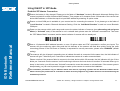
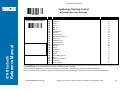
Symbology Reading Control
♦ UPC/EAN Security Level Setting ♦
PROGRAM
Family Code Selection
P.C
UPC/EAN Security Level
SS
SS
SS
Parameter Selection
Level 0
Level 1 Level 2
Option Code
0
1
2
Only available for UPC-A & EAN-13
Reference Manual
IDM Bluetooth
EAN Supplement Control
SS
SS
SS
SS
SS
SS
SS
SS
Disable all specific prefix supplement digital output Enable all specific prefix supplement digital output
Enable 491 Supplement Digit Output
Enable 978/979 Supplement Digit Output
Enable 977 Supplement Digit Output
Enable 378/379 Supplement Digit Output
Enable 414/419 Supplement Digit Output
Enable 434/439 Supplement Digit Output
0
1
2
3
4
5
6
7
UPC/EAN Security Level
The scanner offers three levels of decode security for UPC/EAN bar codes:
Level 0: If you are experiencing misread of poorly-printed or out-of-spec. bar codes, especially in characters 1, 2, 7, and 8 in level 1, please select level 0. Selection of this
security level may significantly impair the decoding ability of the scanner.
Level 1: This is the default setting which allows the scanner to operate fastest, while providing sufficient security in decoding “in-spec” UPC/EAN bar codes.
Level 2: If you are experiencing misread of poorly-printed, soiled or damage bar codes in level 1, please select level 2. This is the most aggressive setting and may
increase the misread.
8014563/WE95/2012-07-25
© SICK AG · Germany · All rights reserved · Subject to change without notice
37
Configure Your IDM BT
S
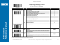
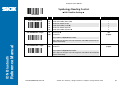
Symbology Reading Control
♦ UCC Coupon Extended Code Setting ♦
PROGRAM
Family Code Selection
P.C
UCC Coupon Extended Code
SS
SS
Parameter Selection
Disable UCC Coupon Extended Code Enable UCC Coupon Extended Code
Option Code
0
1
Reference Manual
IDM Bluetooth
UCC Coupon Extended Code
When UCC coupon extended code function is enabled, scanner decodes UPC-A barcodes starting with digit “5”, EAN-13 barcodes starting with digit “99”, and GS1-128
Coupon Codes. UPC-A, EAN-13 and EAN-128 must be enabled to scan all types of Coupon Codes.
8014563/WE95/2012-07-25
© SICK AG · Germany · All rights reserved · Subject to change without notice
38
Configure Your IDM BT
S
Symbology Reading Control
♦ IATA & Interleaved 2 of 5 Setting ♦
Reference Manual
IDM Bluetooth
PROGRAM
Family Code Selection
P.C
IATA Setting
SS
SS
SS
SS
SS
SS
SS
SS
SS
SS
SS
SS
SS
Disable IATA Enable IATA
Select 15-digit fixed length IATA checking Select variable length IATA
Disable check digit verification Enable check digit automatic verification
Enable S/N checking digit verification only
Enable CPN checking digit verification only
Enable CPN, Airline and S/N check digit verification
Disable check digit transmission Enable check digit transmission
Disable start/stop symbol transmission Enable start/stop symbol transmission
0
1
2
3
4
5
6
7
8
9
A
B
C
Interleaved 2 of 5 Setting
SS
SS
SS
SS
SS
SS
SS
SS
SS
Disable Interleaved 2 of 5
Enable Interleaved 2 of 5 Select Interleaved 2 of 5 as primary format Select German Postal Code as primary format
No check character Validate USS check digit
Validate OPCC check digit
Disable check digit transmission Enable check digit transmission
0
1
2
3
4
5
6
7
8
8014563/WE95/2012-07-25
Parameter Selection
© SICK AG · Germany · All rights reserved · Subject to change without notice
Option Code
39
Configure Your IDM BT
S
Symbology Reading Control
♦ Code 25 Family Setting ♦
Reference Manual
IDM Bluetooth
PROGRAM
Family Code Selection
P.C
Parameter Selection
Code 25 Setting
SS
SS
SS
SS
SS
SS
SS
SS
SS
SS
Disable Standard/Industrial 2 of 5 Enable Standard/Industrial 2 of 5
Disable Matrix 2 of 5 Enable Matrix 2 of 5
Disable China Postal Code Enable China Postal Code
Disable check digit verification Enable check digit verification
Disable check digit transmission Enable check digit transmission
Code 25 Family Min. Length
SS
MS
Default (04) 01-Maximum
Option Code
0
1
2
3
4
5
6
7
8
9
FIN
(2 digits)
Scan 2 digits from the option code chart in Appendix, then IDM BT will terminate this
selection automatically.
Code 25 Family Max. Length
SS
MS
Default (98) 98-Minimum
FIN
(2 digits)
Scan 2 digits from the option code chart in Appendix, then IDM BT will terminate this
selection automatically.
For Code25 setting, we recommend you to select only one type of Code 25 or set the maximum/minimum bar code length. To decode all types of Code 25 or to variable
length of Code 25 will increase the possibility of reading error.
8014563/WE95/2012-07-25
© SICK AG · Germany · All rights reserved · Subject to change without notice
40
Configure Your IDM BT
S
Symbology Reading Control
♦ Code 11 & Code 93 Setting ♦
PROGRAM
Family Code Selection
P.C
Parameter Selection
Code 11 Setting
SS
SS
SS
SS
SS
SS
SS
Disable Code 11 Enable Code 11
Disable check digit verification Select 1-check digit verification
Select 2-check digit verification
Disable check digit transmission Enable check digit transmission
Code 11 Min. Length
SS
MS
Default (04) 01-Maximum
Option Code
0
1
2
3
4
5
6
FIN
(2 digits)
Scan 2 digits from the option code chart in Appendix, then IDM BT will terminate this
selection automatically.
Reference Manual
IDM Bluetooth
Code 11 Max. Length
SS
MS
Default (98) 98-Minimum
FIN
(2 digits)
Scan 2 digits from the option code chart in Appendix, then IDM BT will terminate this
selection automatically.
Code 93 Setting
SS
SS
SS
SS
Disable Code 93
Enable Code 93 Disable check digit transmission Enable check digit transmission
Code 93 Min. Length
SS
MS
Default (01) 01-Maximum
0
1
2
3
FIN
(2 digits)
Scan 2 digits from the option code chart in Appendix, then IDM BT will terminate this
selection automatically.
Code 93 Max. Length
SS
MS
Default (98) 98-Minimum
FIN
(2 digits)
Scan 2 digits from the option code chart in Appendix, then IDM BT will terminate this
selection automatically.
8014563/WE95/2012-07-25
© SICK AG · Germany · All rights reserved · Subject to change without notice
41
Configure Your IDM BT
S
Symbology Reading Control
♦ MSI/Plessey Setting ♦
PROGRAM
Family Code Selection
P.C
Parameter Selection
MSI/Plessey Setting
SS
SS
SS
SS
SS
SS
SS
Disable MSI/Plessy Enable MSI/Plessy
Select MOD 10 check digit Select MOD 10-10 check digit
Select MOD 11-10 check digit
Disable check digit transmission Enable check digit transmission
MSI/Plessey Min. Length
SS
MS
Default (04) 01-Maximum
Option Code
0
1
2
3
4
5
6
FIN
(2 digits)
Scan 2 digits from the option code chart in Appendix, then IDM BT will terminate this
selection automatically.
Reference Manual
IDM Bluetooth
MSI/Plessey Max. Length
SS
MS
Default (98) 98-Minimum
FIN
(2 digits)
Scan 2 digits from the option code chart in Appendix, then IDM BT will terminate this
selection automatically.
8014563/WE95/2012-07-25
© SICK AG · Germany · All rights reserved · Subject to change without notice
42
Configure Your IDM BT
S
Symbology Reading Control
♦ Code 128 & UCC/EAN 128 Setting ♦
PROGRAM
Family Code Selection
P.C
Parameter Selection
Code 128/EAN-128 Setting
SS
SS
SS
SS
SS
SS
Disable Code 128 and GS1-128
Enable Code 128 and GS1-128 Disable function code conversion Enable function code conversion
ISBT Concatenation Off ISBT Concatenation On
Code 128/EAN-128 Min. Length
SS
MS
Default (01) 01-Maximum
Option Code
0
1
2
3
4
5
FIN
(2 digits)
Scan 2 digits from the option code chart in Appendix, then IDM BT will terminate this
selection automatically.
Reference Manual
IDM Bluetooth
Code 128/EAN-128 Max. Length
SS
MS
Default (98) 98-Minimum
FIN
(2 digits)
Scan 2 digits from the option code chart in Appendix, then IDMBT will terminate this
selection automatically.
8014563/WE95/2012-07-25
© SICK AG · Germany · All rights reserved · Subject to change without notice
43
Configure Your IDM BT
S
Symbology Reading Control
♦ UK/Plessey Setting ♦
PROGRAM
Family Code Selection
P.C
Parameter Selection
UK/Plessey Setting
SS
SS
SS
SS
SS
SS
SS
SS
Disable UK/Plessey Enable UK/Plessey
Select UK/Plessey Standard Format Select UK/Plessey CLSI Format
Disable Convert X to A-F Enable Convert X to A-F
Disable check digit transmission Enable check digit transmission
UK/Plessey Min. Length
SS
MS
Default (04) 01-Maximum
Option Code
0
1
2
3
4
5
6
7
FIN
(2 digits)
Reference Manual
IDM Bluetooth
Scan 2 digits from the option code chart in Appendix, then IDM BT will terminate this
selection automatically.
UK/Plessey Max. Length
SS
MS
Default (98) 98-Minimum
FIN
(2 digits)
Scan 2 digits from the option code chart in Appendix, then IDM BT will terminate this
selection automatically.
8014563/WE95/2012-07-25
© SICK AG · Germany · All rights reserved · Subject to change without notice
44
Configure Your IDM BT
S
Symbology Reading Control
♦ Telepen Setting ♦
PROGRAM
Family Code Selection
P.C
Parameter Selection
Telepen Setting
SS
SS
SS
SS
SS
SS
Disable Telepen Enable Telepen
Select Telepen Numeric mode Select Telepen Full ASCII mode
Disable check digit transmission Enable check digit transmission
Telepen Min. Length
SS
MS
Default (04) 01-Maximum
Option Code
0
1
2
3
4
5
FIN
(2 digits)
Scan 2 digits from the option code chart in Appendix, then IDM BT will terminate this
selection automatically.
Reference Manual
IDM Bluetooth
Telepen Max. Length
SS
MS
Default (98) 98-Minimum
FIN
(2 digits)
Scan 2 digits from the option code chart in Appendix, then IDM BT will terminate this
selection automatically.
8014563/WE95/2012-07-25
© SICK AG · Germany · All rights reserved · Subject to change without notice
45
Configure Your IDM BT
S
Symbology Reading Control
♦ GS1 DataBar Setting ♦
PROGRAM
Family Code Selection
P.C
Parameter Selection
GS1 DataBar Setting
SS
SS
SS
SS
SS
SS
Disable GS1 DataBar (RSS-14)
Enable GS1 DataBar (RSS-14) Disable GS1 DataBar Limited
Enable GS1 DataBar Limited Disable GS1 DataBar Expanded
Enable GS1 DataBar Expanded GS1 DataBar Min. Length
SS
MS
Default (04) 01-Maximum
Option Code
0
1
2
3
4
5
FIN
(2 digits)
Only available for Expanded GS1 Databar.
Reference Manual
IDM Bluetooth
Scan 2 digits from the option code chart in Appendix, then IDMBT will terminate this
selection automatically.
GS1 DataBar Max. Length
SS
MS
Default (74) 74-Minimum
FIN
(2 digits)
Only available for Expanded GS1 Databar.
Scan 2 digits from the option code chart in Appendix, then IDM BT will terminate this
selection automatically.
8014563/WE95/2012-07-25
© SICK AG · Germany · All rights reserved · Subject to change without notice
46
Configure Your IDM BT
S
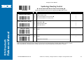
Symbology Reading Control
♦ Linear-stacked & Korea Post Code Setting ♦
Reference Manual
IDM Bluetooth
PROGRAM
Please note that stacked code only can be identified with IDMxxx PDF versions
Family Code Selection
P.C
Parameter Selection
Option Code
Composite Codes Setting
SS
SS
SS
SS
Disable composite codes Enable composite codes
UPC Composite Mode: UPC never linked UPC Composite Mode: UPC always linked
0
1
2
3
PDF417/MicroPDF417 Setting
SS
SS
SS
SS
Disable PDF417
Enable PDF417 Disable MicroPDF417 Enable MicroPDF417
0
1
2
3
Codablock F Setting
SS
SS
Disable Enable
0
1
Korea Post Code Setting
SS
SS
Disable Enable
0
1
Length fixed in 6 characters.
Composite Codes Setting
If UPC Composite Mode: UPC never linked is selected; UPC barcodes are transmitted regardless of whether a MicroPDF417 symbol is detected.
If UPC Composite Mode: UPC always linked is selected, UPC barcodes are only transmitted when the MicroPDF417 is detected.
8014563/WE95/2012-07-25
© SICK AG · Germany · All rights reserved · Subject to change without notice
47
Configure Your IDM BT
S
Keyboard Interface Control
♦ Keyboard Layout (Language) Setting ♦
Reference Manual
IDM Bluetooth
PROGRAM
Family Code Selection
P.C
Keyboard Layout
SS
SS
SS
SS
SS
SS
SS
SS
SS
SS
SS
SS
SS
SS
SS
SS
SS
SS
Parameter Selection
Option Code
USA (QWERTY) France (AZERTY)
Germany (QWERTZ)
United Kingdom - UK (QWERTY)
Canadian French (QWERTY)
Spain (Spanish, QWERTY)
Sweden/Finland (QWERTY)
Portugal (QWERTY)
Norway (QWERTY)
Spain (Latin America, QWERTY)
Italy (QWERTY)
Netherlands (QWERTY)
Denmark (QWERTY)
Belgium (AZERTY)
Switzerland-Germany (QWERTY)
Iceland (QWERTY)
Japan (DOS/V)
Czech (QWERTY)
00
01
02
03
04
05
06
07
08
09
10
11
12
13
14
15
16
17
Please refer to the ASCII/HEX Table listed in the Appendix to determine HEX codes for characters, symbols, and functions to be used as preamble or postamble.
To set preamble or postamble as function key output, you must enable the “Function Key Emulation” feature as listed in page 3-25 first.
Keyboard Interface Message String :
Preamble
Data Length
Prefix Symbol ID
Scanned Data
Suffix Symbol ID
Postamble
Record Suffix
1-15 characters
2-3 digits
1 or 2 characters
Variable length
1 or 2 characters
1-15 characters
1 character
8014563/WE95/2012-07-25
© SICK AG · Germany · All rights reserved · Subject to change without notice
48
Configure Your IDM BT
S
Keyboard Interface Control
♦ Record Suffix, Preamble, Postamble & Caps Lock ♦
PROGRAM
Family Code Selection
P.C
Parameter Selection
Record Suffix
SS
SS
SS
SS
SS
SS
None
RETURN TAB
SPACE
ENTER (Numeric Key Pad)
User defined character (1 character)
Preamble
SS
MS
None 1-15 characters
Option Code
0
1
2
3
4
5, (00-7F)
FIN
[00-7F], [FIN]
Maximum 15-character input; scan “FIN” to terminate this selection.
Reference Manual
IDM Bluetooth
Postamble
SS
MS
None 1-15 characters
FIN
[00-7F], [FIN]
Maximum 15-character input; scan “FIN” to terminate this selection.
Caps Lock Control
SS
SS
SS
“Caps Lock Off” State “Caps Lock On” State
Auto Detect (PC/AT, PS/2, Keyboard Replacement and DOS/V Machines only)
0
1
2
Caps Lock Release Control
SS
SS
“Caps Lock On, Caps Off” “Caps Lock On, Shift Off”
0
1
The function of “Caps Lock Control” and “Key Pad Emulation” are only available for IBM PC/AT, PS/VP, PS/2 series personal computers and compatible machines.
While selecting the other host interfaces, these selections don’t perform the above functions for you.
Please check the actual Caps Lock state in use while software application is running. If the Caps Lock state is off, select “Caps Lock Off” state, then IDM BT will perform
normal data transmission. If the Caps Lock state is on, select “Caps Lock On” state. Select “Auto Detect”, IDM will perform special transmission handshaking without
changing the status of Caps Lock switch.
8014563/WE95/2012-07-25
© SICK AG · Germany · All rights reserved · Subject to change without notice
49
Configure Your IDM BT
S
Keyboard Interface Control
♦ Delay Setting ♦
PROGRAM
Family Code Selection
P.C
Intermessage Delay
SS
MS
Parameter Selection
None 1-99 (x10) msec.
Option Code
FIN
(2 digits)
Scan 2 digits from the option code chart in Appendix, then IDM BT will terminate this
selection automatically.
Intercharacter Delay
SS
MS
None 1-99 (x5) msec.
FIN
(2 digits)
Scan 2 digits from the option code chart in Appendix, then IDM BT will terminate this
selection automatically.
Interfunction Delay
SS
MS
None 1-99 (x5) msec.
FIN
(2 digits)
Reference Manual
IDM Bluetooth
Scan 2 digits from the option code chart in Appendix, then IDM BT will terminate this
selection automatically.
Intermessage Delay is a time delay between messages output by IDM. Increasing this delay will help host applications process the incoming data on time.
Intercharacter Delay is a time delay between data characters output by IDM. These two parameters are used to synchronize data communication when : 1) the data
transmission speed is too fast, characters may be skipped; 2) multitasking operation system or host computers in a network may slow down the keyboard handling; 3)
various notebook or desktop PC systems require different timing parameter settings. Please always add one extra unit as safety margin when adjusting these two
parameters.
Interfunction Delay is a time delay between the transmission of each segment of the message string.
Intermessage Delay, Intercharacter Delay and Interfunction Delay cannot be only worked under SPP and HID modes.
8014563/WE95/2012-07-25
© SICK AG · Germany · All rights reserved · Subject to change without notice
50
Configure Your IDM BT
S
Keyboard Interface Control
♦ Emulation Setting & Upper/Lower Case Setting ♦
PROGRAM
Family Code Selection
P.C
Function Key Emulation
SS
SS
Parameter Selection
Enable ASCII 00-31 code as keyboard function code output Ctrl-Output
Option Code
0
1
Key Pad Emulation
SS
SS
Disable key pad emulation Enable numeric output as key pad (Num Lock On) output
0
1
Upper/Lower Case
SS
SS
SS
SS
Normal case (neglect the upper/lower case control) Inverse case (change all characters output to inverse case)
Upper case (force all characters output as upper case)
Lower case (force all characters output as lower case)
0
1
2
3
Reference Manual
IDM Bluetooth
Refer to Appendix – Keyboard Function Code Table for details.
8014563/WE95/2012-07-25
© SICK AG · Germany · All rights reserved · Subject to change without notice
51
Configure Your IDM BT
S
Serial Interface Control
♦ Record Suffix, Preamble ,Postamble Setting ♦
PROGRAM
Family Code Selection
P.C
STX/ETX Control
SS
SS
Parameter Selection
Option Code
Disable STX/ETX transmission Enable STX/ETX transmission
0
1
Reference Manual
IDM Bluetooth
STX/ETX is two characters used to indicate the starting and ending of the total data
frame transmitted via serial interface.
Record Suffix
SS
SS
SS
SS
SS
SS
MS
None
CR (0DH) LF (0AH)
CRLF (0D0AH)
TAB (09H)
SPACE (20H)
User defined character (1 character)
Preamble
SS
MS
None 1-15 characters
0
1
2
3
4
5
6, (00-7F)
FIN
[00-7F], [FIN]
Maximum 15-character input; scan “FIN” to terminate this selection.
Postamble
SS
MS
None 1-15 characters
FIN
[00-7F], [FIN]
Maximum 15-character input; scan “FIN” to terminate this selection.
Serial Interface Message String (RS232, USB COM) :
STX
Preamble
Data Length
Prefix Symbol ID
Scanned Data
Suffix Symbol ID
Postamble
ETX
Record Suffix
1 character
1-15 characters
2-3 digits
1 or 2 characters
Variable length
1 or 2 characters
1-15 characters
1 character
1 character
8014563/WE95/2012-07-25
© SICK AG · Germany · All rights reserved · Subject to change without notice
52
Configure Your IDM BT
S
Serial Interface Control
♦ Delay Setting ♦
PROGRAM
Family Code Selection
P.C
Intermessage Delay
SS
MS
Parameter Selection
None 1-99 (x10) msec.
Option Code
FIN
(2 digits)
Scan 2 digits from the option code chart in Appendix, then IDM BT will terminate this
selection automatically.
Intercharacter Delay
SS
MS
None 1-99 (x5) msec.
FIN
(2 digits)
Scan 2 digits from the option code chart in Appendix, then IDM BT will terminate this
selection automatically.
Interfunction Delay
SS
MS
None 1-99 (x5) msec.
FIN
(2 digits)
Reference Manual
IDM Bluetooth
Scan 2 digits from the option code chart in Appendix, then IDM BT will terminate this
selection automatically.
Intermessage Delay is a time delay between messages output by IDM. Increasing this delay will help host applications process the incoming data on time.
Intercharacter Delay is a time delay between data characters output by IDM. These two parameters are used to synchronize data communication when : 1) the data
transmission speed is too fast, characters may be skipped; 2) multitasking operation system or host computers in a network may slow down the keyboard handling; 3)
various notebook or desktop PC systems require different timing parameter settings. Please always add one extra unit as safety margin when adjusting these two
parameters.
Interfunction Delay is a time delay between the transmissions of each segment of the message string.
Intermessage Delay, Intercharacter Delay and Interfunction Delay cannot be only worked under SPP and HID modes.
8014563/WE95/2012-07-25
© SICK AG · Germany · All rights reserved · Subject to change without notice
53
Configure Your IDM BT
S
Serial Interface Control
♦ Protocol, Baud Rate, Data Frame, ACK/NAK Setting ♦
Reference Manual
IDM Bluetooth
PROGRAM
Family Code Selection
P.C
Handshaking Protocol
SS
SS
SS
SS
None (free running mode) RTS/CTS (hardware handshaking)
ACK/NAK (software handshaking)
Xon/Xoff (software handshaking)
NAK Retry Count
SS
SS
3 times 0~255 times
ACK/NAK Transmission Indication
SS
SS
SS
SS
Disable
Enable Disable ACK Indication
Enable ACK Indication
Baud Rate (BPS)
SS
SS
SS
SS
38.4K BPS
19.2K BPS
9600 BPS 4800 BPS
2400 BPS
1200 BPS
57.6K BPS
115.2K BPS
0
1
2
3
4
5
8
9
Data Frame
SS
SS
SS
SS
SS
SS
SS
SS
8, None, 1 8, Odd, 1
8, Even, 1
8, Space, 1
8, Mark, 1
8, None, 2
7, Odd, 1
7, Even, 1
7, Space, 1
7, Mark, 1
7, None, 2
7, Odd, 2
7, Even, 2
7, Space, 2
7, Mark, 2
0
1
2
3
4
5
6
7
8
9
A
B
C
D
E
8014563/WE95/2012-07-25
Parameter Selection
Option Code
0
1
2
3
FIN
(3 digits)
0
1
2
3
© SICK AG · Germany · All rights reserved · Subject to change without notice
54
Configure Your IDM BT
S
Serial Interface Control
♦Time Out Setting ♦
PROGRAM
Family Code Selection
P.C
Serial Response Time-out
SS
SS
SS
SS
SS
SS
Parameter Selection
None
200 mseconds
500 mseconds 800 mseconds
1 second
2 seconds
3 seconds
4 seconds
5 seconds
8 seconds
10 seconds
15 seconds
Option Code
0
1
2
3
4
5
6
7
8
9
A
B
Reference Manual
IDM Bluetooth
When the RTS/CTS Hardware Handshaking option is selected, the RTS (request to send) and CTS (clear to send) signals will be issued before normal data
communication. This option is very helpful to ensure the reliability of data communication.
When the ACK/NAK Software Handshaking option is selected, the IDM BT waits for an ACK (acknowledge) or NAK (not acknowledge) from the host computer after each
data transmission. If the NAK is received, IDM will re-send the data until receiving ACK.
The Serial Response Time-out is a pre-defined delay time for IDM BT to wait for handshaking, acknowledgment or non-acknowledgment from the host computer.
8014563/WE95/2012-07-25
© SICK AG · Germany · All rights reserved · Subject to change without notice
55
Configure Your IDM BT
S
Wand/Laser Emulation Control
♦ Output Polarity, Signal State, Margin/Module Time, etc. ♦
PROGRAM
Family Code Selection
P.C
Output Polarity
SS
SS
Parameter Selection
Option Code
High level (5Vdc) on Bar (low level on Space) Low level (0Vdc) on Bar (high level on Space)
0
1
Determine the output voltage level for both bar and space.
Initial Signal State
SS
SS
High Level (5Vdc) Low Level (0Vdc)
0
1
Reference Manual
IDM Bluetooth
Determine the initial state of output voltage level.
Margin Time
SS
SS
SS
SS
10 msec.
15 msec.
20 msec. 25 msec.
30 msec.
50 msec.
100 msec.
Delay time before data transmission
0
1
2
3
4
5
6
Module Time
SS
SS
SS
Extremely short
Short
Medium Long
0
1
2
3
Narrow/Wide Ratio
SS
SS
SS
1:2 1:2.5
1:3
0
1
2
Code 39/Code 128 Emulation
SS
SS
SS
SS
SS
Disable standard Code 39 emulation Enable standard Code 39 skip emulation
Enable standard Code 39 replace emulation
Enable Full ASCII Code 39 emulation
Enable Code 128 emulation
0
1
2
3
4
Time base of minimum narrow bar
[ Code 39 Skip ] : When this option is selected, all scanned data will be translated as Standard Code 39 wand/laser emulation output. If any lower case characters are read,
they will be translated to upper case characters. Any other characters that are not available in Code 39 symbology set will be skipped.
[ Code 39 Replace] : Any character not normally available in the standard Code 39 symbology set, will be translated as Space.
8014563/WE95/2012-07-25
© SICK AG · Germany · All rights reserved · Subject to change without notice
56
Configure Your IDM BT
S
Operation Control
♦ Operation Mode ♦
PROGRAM
Family Code Selection
P.C
Operation Mode
SS
SS
Parameter Selection
Trigger mode Presentation mode
Option Code
1
2
Reference Manual
IDM Bluetooth
Trigger Mode (Low Power Triggering) The scanner goes into standby state after scanning the bar code. You must press the trigger to turn on the light source of the
scanner before scanning the bar code.
Presentation Mode (Auto Detection) Presentation mode uses ambient light to detect the bar codes. The light source is off until the scanner detects an image which is
similar to a barcode. Then the light source turns on automatically to read the bar code. If the light level in the room is not high enough, Presentation Mode may not work
properly. You can choose different level of “Presentation Sensitivity” to meet your application (Please refer to the setting of “ Presentation Sensitivity”).
8014563/WE95/2012-07-25
© SICK AG · Germany · All rights reserved · Subject to change without notice
57
Configure Your IDM BT
S
Operation Control
♦ Buzzer, Indicator, Vibrator, Inverse Reading ♦
Reference Manual
IDM Bluetooth
PROGRAM
Family Code Selection
P.C
Parameter Selection
Option Code
Buzzer Tone Adjust
SS
SS
SS
SS
SS
SS
SS
Buzzer tone – mute
Buzzer tone – low
Buzzer tone – medium Buzzer tone – high
Buzzer tone - extremely high
Power-on beep No power-on beep
0
1
2
3
4
5
6
Power On Indicator
SS
SS
SS
Disable (LED off)
LED steady on LED flash
0
1
2
Good Read Indicator
SS
SS
Disable
Enable 0
1
Vibrator Control
SS
SS
Disable
Enable 0
1
Optional function, only available for vibrator model.
Inverse Reading
SS
SS
Disable Enable
0
1
Beeping Control
SS
SS
SS
SS
Radio Connected/ Disconnected Beep On Radio Connected/ Disconnected Beep Off
Battery Power Low Beep On Battery Power Low Beep Off
0
1
2
3
8014563/WE95/2012-07-25
© SICK AG · Germany · All rights reserved · Subject to change without notice
58
Configure Your IDM BT
S
Operation Control
♦ Dollar Sign Control, Redundancy, Scan Rate Control ♦
Reference Manual
IDM Bluetooth
PROGRAM
Family Code Selection
P.C
Parameter Selection
Option Code
Dollar Sign Control
SS
SS
SS
SS
SS
Dollar sign output as “ $ “ Dollar sign output as “¥“
Dollar sign output as “ € “
Dollar sign output as “ £ “
Dollar sign output as “ ¢ “
0
1
2
3
4
Redundancy
SS
SS
SS
SS
SS
SS
None
Level 1 Level 2
Level 3
Level 4
Level 5
To prevent potential miss reading.
0
1
2
3
4
5
Scan Rate Control
SS
SS
Dynamic Fixed
0
1
The Redundancy is the number of times the same bar code label has to be decoded before it is transmitted. scanner before scanning the bar code.
Scan Rate Control: The scanner will have better motion tolerance when you select “Fixed” scan rate. It’s suitable for application which needs higher motion tolerance on
the move. But this may impact to the reading distance.
8014563/WE95/2012-07-25
© SICK AG · Germany · All rights reserved · Subject to change without notice
59
Configure Your IDM BT
S
Operation Control
♦ Delay Setting ♦
PROGRAM
Family Code Selection
P.C
Reread Delay
SS
SS
SS
SS
SS
SS
Disable
Immediate time out Short time out
Medium time out
Long time out
Force verification
0
1
2
3
4
5
SS
SS
SS
SS
SS
SS
SS
None 200 msec.
500 msec.
1 sec.
1.5 sec.
2 sec.
3 sec.
0
1
2
3
4
5
6
(Double Scan Verification)
Reference Manual
IDM Bluetooth
Good Read Delay
Parameter Selection
Option Code
The Reread Delay (Double Scan Verification) is designed to inhibit IDM from reading the same bar code label twice in pre-defined short duration. Force Verification will
not allow reading of the same bar code twice.
This Good Read Delay is the minimum amount of time before the scanner can read another bar code.
8014563/WE95/2012-07-25
© SICK AG · Germany · All rights reserved · Subject to change without notice
60
Configure Your IDM BT
Reference Manual
IDM Bluetooth
S
Operation Control
♦ Time-out Setting, Good Read Duration ♦
PROGRAM
Family Code Selection
P.C
Parameter Selection
Option Code
Light Source On Time
SS
SS
SS
SS
Short Medium
Long
Extremely long
0
1
2
3
Hands Free Time-out
SS
SS
SS
SS
SS
Short Medium
Long
Extremely long
Disable
0
1
2
3
4
Good Read Duration
SS
SS
SS
SS
SS
Short
Medium Long
Extremely long
Extremely short
0
1
2
3
4
Time Delay to Low Power Trigger
SS
SS
SS
SS
SS
SS
1 sec
3 secs
5 secs
7 secs
9 secs
Immediate 0
1
2
3
4
5
The Light Source On Time is a pre-defined light source time out counter for Alternative Mode, Presentation Mode and Level Mode. The scanner keeps the light source on
till the pre-defined light source on time is up. You can adjust this parameter to meet your own application requirement.
The Presentation Mode is referred to as “hands free” mode. The hands free mode will be automatically changed to manual trigger mode when you press the trigger. You
can remain the scanner in manual trigger mode by setting the Hands Free Time-Out. Once the time-out duration is up (if there’s no any trigger operation), the imager will
revert to the original hands free mode.
The Time Delay to Low Power Trigger sets the time for scanner to enter low power trigger mode after any scanning activity.
8014563/WE95/2012-07-25
© SICK AG · Germany · All rights reserved · Subject to change without notice
61
Configure Your IDM BT
S
Operation Control
♦ Presentation Scanning Setting, Laser Aiming Control ♦
PROGRAM
Family Code Selection
P.C
Stand Power Off Timeout
SS
SS
SS
Parameter Selection
Option Code
3 mins 5 mins
10 mins
0
1
2
Reference Manual
IDM Bluetooth
Only available for SICK IDM Laser model
Presentation Auto-sense
SS
SS
Disable Enable
Presentation Sensitivity
SS
SS
SS
SS
SS
Level 1
Level 2
Level 3
Level 4
Level 5 Laser Aiming Control
SS
SS
Disable
Enable 0
1
Level 6
Level 7
0
1
2
3
4
5
6
0
1
Only relevant for models with integrated laser aimer.
The Stand Power Off Timeout is a pre-defined duration for scanner’s light source on time when the scanner is placed on Stand. While the scanner is placed on Stand, the
scanner’s will be switched from hand-held scanning to presentation scanning and the light source will be forced on automatically. The light source will be off when the
pre-defined duration is up.
When enable the Presentation Auto-sense, the scanner can be switched between hands free scanning and hand-held scanning automatically when working with the
Stand or cradle
The Presentation Sensitivity is used to configure the sensitivity level when the scanner is set as presentation mode. The higher lever means higher sensitivity for detecting
the barcode.
8014563/WE95/2012-07-25
© SICK AG · Germany · All rights reserved · Subject to change without notice
62
Configure Your IDM BT
S
Operation Control
♦ Out-of-range Scanning, Sleep Time-out Control ♦
PROGRAM
Family Code Selection
P.C
Parameter Selection
Option Code
Out-of-range Scanning
SS
SS
Disable Enable
0
1
Link Supervision Time-out
SS
SS
SS
SS
SS
1 sec
3 secs 5 secs
7 secs
9 secs
0
1
2
3
4
Reference Manual
IDM Bluetooth
Only available in PAIR & PICO modes
Sleep Time-out of Connect State
SS
MS
6 (x5) minutes 0-99 (x5) minutes
FIN
(2 digits)
Sleep Time-out of Disconnect State
SS
MS
1 minute 0-99 minutes
FIN
(2 digits)
Out-of-range Scanning when radio link is built between the scanner and remote host device, the scanner will transmit each scanned data right after scanning the barcode
data. However, the scanner is preset for unable to scan any barcode data when it loses the radio connection. You can enable the Out-of-range Scanning function to
continue scanning barcode data into memory buffer until radio link resumed.
The Link Supervision Time-out is a pre-defined radio link supervision timeout setting. The scanner will supervise the radio link status every preset seconds.
The Sleep Time-out Control can be set under radio connection or disconnection state. If the scanner is not used within the preset time-out duration, it will automatically
enter “Sleep State” for power saving purpose. You are able to disable this function by setting the time-out duration to “0”.
8014563/WE95/2012-07-25
© SICK AG · Germany · All rights reserved · Subject to change without notice
63
Configure Your IDM BT
S
Operation Control
♦ Batch Scanning Setting ♦
Reference Manual
IDM Bluetooth
PROGRAM
Family Code Selection
P.C
Parameter Selection
Option Code
Batch Scanning Link Control
SS
SS
Radio disable
Radio enable 0
1
Stored Data Transmission
SS
SS
SS
All
On cradle
Scan barcode 0
1
2
Delete Stored Data after
Transmission
SS
SS
Disable Enable
0
1
The Batch Scanning Link Control is a pre-defined radio option to control the radio-on or radio-off status under batch scanning operation. Please note that if the radio
disable is activated, the radio link will be disconnected once you enter batching scanning. The radio link will be resumed when you transmit the stored data or exit batch
scanning.
The Stored Data Transmission is a pre-defined approach when you want to transmit the scanned data under batch scanning operation. You can transmit the scanned data
by placing the scanner onto the cradle or scanning “Transmit Stored Data” command, or by either one of both methods.
In batching scanning, the default setting of Delete Stored Data after Transmission is disabling. The scanner will keep all stored data after transmission until you scan the
“Clear All Stored Data” command. You are also able to delete all stored data after transmission automatically by enabling this function.
8014563/WE95/2012-07-25
© SICK AG · Germany · All rights reserved · Subject to change without notice
64
Configure Your IDM BT
S
Operation Control
♦ Batch Scanning Data Transmission Setting ♦
Reference Manual
IDM Bluetooth
PROGRAM
Family Code Selection
P.C
Parameter Selection
Option Code
Field Delimiter
SS
SS
SS
SS
SS
SS
None
,
SPACE
–
.
User define
Batch Data Quantity Output Format
SS
SS
SS
As many times as the quantity indicates <Quantity><Field Delimiter><Scanned Data>
<Scanned Data><Field Delimiter><Quantity>
0
1
2
Data Transmission Format
SS
SS
SS
Disable (scanned data only) Leading with MAC address (MAC address and scanned data)
Leading with ID No. (scanner ID and scanned data)
0
1
2
0
1
2
3
4
5, [00-7F]
Only available for RS232, USB HID and USB COM interface in PAIR & PICO modes
The Field Delimiter is used to separate the specific information and scanned data into two fields. You can choose desired delimiter format.
The Batch Data Quantity Output Format If you want to input the quantity information of barcode data, you can enter the quantity from 1 to 9999 by scanning the quantity
barcodes right after you scanned the barcode data. The quantity information will be stored into the memory storage together with the barcode data. There are two ways to
output the stored barcode data and quantity information.
In PICO mode, up to 7 scanners can be connected with one smart cradle. The Data Transmission Format can help user to identify the source of the transmitted data.
You can choose to transmit the scanned data leading with MAC address or pre-assigned ID.
Example format: <MAC address><Field Delimiter><Data> or <ID><Field Delimiter><Data>.
8014563/WE95/2012-07-25
© SICK AG · Germany · All rights reserved · Subject to change without notice
65
Configure Your IDM BT
S
Operation Control
♦ Bluetooth Device Name & Security Setting♦
♦
Reference Manual
IDM Bluetooth
PROGRAM
Family Code Selection
P.C
Parameter Selection
Option Code
Bluetooth Device Name
SS
MS
Default device name User define, 1-16 characters
FIN
[00-7F], FIN
Bluetooth PIN Code
SS
MS
Default Bluetooth PIN Code
User define, 1-8 numbers
FIN
[30-39], FIN
Bluetooth Authentication
SS
SS
Disable
Enable 0
1
The default Bluetooth Device Name is “IDMxxxBT--xxxx”, you will be able to change the device name by scanning HEX values (1-16 characters).
The default Bluetooth PIN Code is “00000000”, you will be able to change the PIN Code by scanning HEX values (1-8 numbers).
The Bluetooth Authentication You can enable or disable the Bluetooth Authentication between the scanner and remote host device. If this function is enabled, when the
scanner wants to connect itself and sends the data to the host device, the host device has to return a link key shared between the scanner and the host device.
8014563/WE95/2012-07-25
© SICK AG · Germany · All rights reserved · Subject to change without notice
66
Configure Your IDM BT
S
Operation Control
♦ Bluetooth Other Settings ♦
PROGRAM
Family Code Selection
P.C
Parameter Selection
Option Code
HID Link Quality Setting
SS
SS
Disable
Enable 0
1
Bluetooth Power Saving Mode
SS
SS
Disable Enable
0
1
Reference Manual
IDM Bluetooth
The HID Link Quality Setting while using the HID radio link mode, some errors may occur during the data transmission when the radio link is disconnected. You can
enable this function to prevent such error from occurring.
The Bluetooth Power Saving Mode Bluetooth module will enter low consumption mode when you enable this function.
8014563/WE95/2012-07-25
© SICK AG · Germany · All rights reserved · Subject to change without notice
67
Configure Your IDM BT
S
Condensed DataWizard
♦ Preamble, Postamble, Data Length & Symbol ID Trans. ♦
PROGRAM
Family Code Selection
P.C
Preamble
SS
MS
Parameter Selection
None 1-15 characters
Option Code
FIN
[00-7F], [FIN]
Maximum 15-character input; scan “FIN” to terminate this selection.
Postamble
SS
MS
None 1-15 characters
FIN
[00-7F], [FIN]
Maximum 15-character input; scan “FIN” to terminate this selection.
Data Length Transmission
SS
SS
Disable Enable 2 digits data length transmission
0
1
Reference Manual
IDM Bluetooth
If data length exceeds 99, 3-digit data length will be transmitted.
Symbology ID Transmission
SS
SS
SS
SS
SS
SS
SS
Disable symbology ID transmission Enable prefix symbology ID transmission
Enable suffix symbology ID transmission
Enable both prefix and suffix symbology ID transmission
Enable prefix AIM symbology ID transmission
Enable suffix AIM symbology ID transmission
Enable both prefix and suffix AIM symbology ID transmission
0
1
2
3
4
5
6
DataWizard is the most powerful, Artificial-Intelligence based data editing expert system provided specially for the IDM BT family bar code readers. Through DataWizard,
you can process the scanned data prior the transmissions in many ways as: Insert, Delete, Match, Verify, Replace, Reorganize, and Repeat Transmission. It will help
you to arrange the transmission of scanned data to any specific format without software modification.
Due to the resources used by this system, Full-feature DataWizard is only supported by IDM Set Up Tool. Through the IDM Set Up Tool, all settings and configurations
can be done on-screen, under Windows 95/98/NT/2000/XP environment.
A Condensed Version DataWizard is provided by each IDM series. Through this menu, the condensed DataWizard can be utilized via bar code menu readings with ease.
Please note that all “Character” input should be referred to the ASCII/HEX Table listed in Appendix to find matched HEX value.
If you have any problem to use DataWizard, please refer to following pages for details and consult your local IDM BT vendor or our web site for any assistance.
8014563/WE95/2012-07-25
© SICK AG · Germany · All rights reserved · Subject to change without notice
68
Configure Your IDM BT
S
Condensed DataWizard
♦ Data Formatter Setting ♦
PROGRAM
Family Code Selection
P.C
Formatter Control
SS
MS
MS
1st Insertion
SS
DS
Parameter Selection
Option Code
2nd Option Code
Disable Select one bar code symbology
Select all bar code symbologies
FIN
(2 digits)
00
automatic termination
automatic termination
Disable Enable
FIN
(2 digits)
[1-3 characters], [FIN]
2-digits identified position; max. 3 insertion characters
Reference Manual
IDM Bluetooth
2nd Insertion
SS
DS
Disable Enable
2-digits identified position; max. 3 insertion characters
3rd Insertion
SS
DS
Disable Enable
2-digits identified position; max. 3 insertion characters
4th Insertion
SS
DS
Disable Enable
2-digits identified position; max. 3 insertion characters
position
FIN
(2 digits)
[1-3 characters], [FIN]
position
FIN
(2 digits)
[1-3 characters], [FIN]
position
FIN
(2 digits)
[1-3 characters], [FIN]
position
The Data Formatter is used to edit the scanned raw data prior to transmitting the data to the host computers or terminals. It allows you to select desired bar code
symbologies for formatter control, and provides Multiple Position Insertion and Multiple Character Insertion (max three characters) in the identified position.
While the Data Formatter is enabled, it arranges only scanned data without Preamble, Postamble, STX, ETX, Data Length, Prefix/Suffix Symbolology ID or Record
Suffix. All of the above programmable parameters perform the same function depending on your setting.
Regarding the “Bar Code Selection” and “Position Calculation” of data formatter, please refer to page 65 for details.
Please note that all “Character” input should be referred to the ASCII/HEX Table listed in Appendix to find matched HEX value.
8014563/WE95/2012-07-25
© SICK AG · Germany · All rights reserved · Subject to change without notice
69
Configure Your IDM BT
S
Condensed DataWizard
♦ Data Verifier Setting ♦
PROGRAM
Family Code Selection
P.C
Verifier Control
SS
MS
MS
SS
MS
Identified Data Length
Parameter Selection
Option Code
2nd Option Code
Disable Select one bar code symbology
Select all bar code symbologies
FIN
(2 digits)
00
automatic termination
automatic termination
Disable Enable
FIN
(2 digits)
Determine the identified data length for verification.
1st Identified Character
SS
DS
Disable Enable
Reference Manual
IDM Bluetooth
2-digits checking position; 1 identified character
2nd Identified Character
SS
DS
Disable Enable
2-digits checking position; 1 identified character
3rd Identified Character
SS
DS
Disable Enable
2-digits checking position; 1 identified character
FIN
(2 digits)
[00-7F]
position
FIN
(2 digits)
[00-7F]
position
FIN
(2 digits)
[00-7F]
position
The Data Verifier is used to provide advanced verification for error-free scanning and to work as an Embedded Data Transmitting Filter.
All data must conform to the Identified Bar Code Symbologies, Identified Data Length, and one to three Identified Characters in the checking position. Otherwise, the
IDM BT will not transmit the data to the host computers or terminals, but will instead issue 3 long beeps for verification error and skip the scanned data.
The Data Verifier checks only scanned data without Preamble, Postamble, STX, ETX, Data Length, Prefix/Suffix Symbology ID or Record Suffix.
Regarding the “Bar Code Selection” and “Position Calculation” of Data Verifier, please refer to page 65 for details.
Please note that all “Character” input should be referred to the ASCII/HEX Table listed in Appendix to find matched HEX value.
8014563/WE95/2012-07-25
© SICK AG · Germany · All rights reserved · Subject to change without notice
70
Configure Your IDM BT
S
Condensed DataWizard
♦ Data Replacer Setting ♦
PROGRAM
Family Code Selection
P.C
Replacer Control
SS
MS
MS
1st Replacement
SS
DS
Parameter Selection
Option Code
2nd Option Code
Disable Select one bar code symbology
Select all bar code symbologies
FIN
(2 digits)
00
automatic termination
automatic termination
Disable Enable
FIN
(2 digits)
[00-7F]
2-digits identified position; 1 replacement character
2nd Replacement
SS
DS
Disable Enable
Reference Manual
IDM Bluetooth
2-digits identified position; 1 replacement character
3rd Replacement
SS
DS
Disable Enable
2-digits identified position; 1 replacement character
position
FIN
(2 digits)
[00-7F]
position
FIN
(2 digits)
[00-7F]
position
The Data Replacer is used to edit the scanned raw data prior to transmitting the data to the host computers or terminals. It allows you to select desired bar code
symbologies for replacer control, and provides Multiple Position Replcement in the identified position.
All data must conform to the Identified Bar Code Symbologies, and one to three Identified Characters in the identified position while the Data Replacer is enabled; it
arranges only scanned data without Preamble, Postamble, STX, ETX, Data Length, Prefix/Suffix Symbology ID or Record Suffix.
Regarding the “Bar Code Selection” and “Position Calculation” of Data Replacer, please refer to page 65 for details.
Please note that all “Character” input should be referred to the ASCII/HEX Table listed in Appendix to find mathced HEX value.
8014563/WE95/2012-07-25
© SICK AG · Germany · All rights reserved · Subject to change without notice
71
Configure Your IDM BT
S
Condensed DataWizard
♦ Data Organizer Setting ♦
PROGRAM
Family Code Selection
P.C
Organizer Control
SS
MS
MS
SS
DS
1st Organization
Reference Manual
IDM Bluetooth
2nd Organization
Include/Exclude Control
SS
DS
SS
DS
Parameter Selection
Option Code
2nd Option Code
Disable Select one bar code symbology
Select all bar code symbologies
FIN
(2 digits)
00
automatic termination
automatic termination
Disable Enable
FIN
(2 digits)
2-digits identified position;
Forward/backward data transmission setting
position
direction
Disable Enable
FIN
(2 digits)
2-digits identified position;
Forward/backward data transmission setting
position
direction
Transmitted data excluded the data of identified position Transmitted data included the data of identified position
0 (Forward) 1 (Backward)
0 (Forward) 1 (Backward)
0
1
The Data Organizer is used to edit the scanned raw data prior to transmitting the data to the host computers or terminals. It allows you to select desired bar code
symbologies for organizer control, and provides maximum two identified positions to send the data forward or backward. It also allows you to control the transmitted data
including or excluding the data of identification position. Please refer to the application example listed in page 65 for details.
While the Data Organizer is enabled, it arranges only scanned data without Preamble, Postamble, STX, ETX, Data Length, Prefix/Suffix Symbology ID or Record
Suffix.
Regarding the “Bar Code Selection” and “Position Calculation” of Data Organizer, please refer to page 65 for details.
Please note that all “Character” input should be referred to the ASCII/HEX Table.
8014563/WE95/2012-07-25
© SICK AG · Germany · All rights reserved · Subject to change without notice
72
Configure Your IDM BT
S
[Data Verifier, Data Replacer, Data Organizer]
Select a Bar Code Symbology
Reference Manual
IDM Bluetooth
You can select one or all types of bar code symbologies to
use Condensed DataWizard for advanced transmission
arrangement. If you scan “00” to select all types, the IDM BT
will arrange all incoming data to meet your pre-defined
format. If you want to select only one type bar code, please
select one of the option code listed below.
Code 128 : 01
EAN-8 : 05
Code 93 : 09
UCC/EAN 128 : 31
EAN-8 with 2 supple : 35
Code 11 : 10
UPC-A : 02
EAN-8 with 5 supple.: 45
MSI/Plessey : 11
UPC-A with 2 supple.: 32
Codabar/NW-7 : 06
UK/Plessey : 12
UPC-A with 5 supple.: 42
Code 39 : 07
Telepen : 13
UPC-E : 03
Code 32 : 37
GS1 Data Bar : 14
UPC-E with 2 supple.: 33
Trioptic Code 39: 47
IATA : 15
UPC-E with 5 supple.: 43
Matrix 2 of 5 : 38
Coupon Code : 16
EAN-13 : 04
Interleaved 2 of 5 : 48
PDF417/MicroPDF417: 22
EAN-13 with 2 supple. : 34
China Postal Code : 58
Codablock: 23
EAN-13 with 5 supple. : 44
German Postal Code : 68
Korea Post Code: 26
Example: If there is a 11-character data string, please
refer to the following to calculate the actual position for
identification.
X
X
X
X
X
X
X
X
X
X
X
00
01
02
03
04
05
06
07
08
09
10
Application Example
If your bar code label is a 16-digit Interleaved 2 of 5 which
includes the information of 6-digit date code, 6-digit serial
number and 4-digit unit price, you want the IDM BT do the
following for you without software modification:
Apply only Interleaved 2 of 5 to the condensed
DataWizard.
Check bar code is actually with 16-digit length.
Allow bar code output whose date code is leading with
“9”.
Position Calculation
Three outputs with “TAB” suffix.
[Data Formatter]
The date code output should skip “9” and replaced it by
“A”.
Example: If there is a 5-character input data string, refer to
the following to calculate the actual position for insertion:
X
00
X
01
X
02
X
03
X
04
05
The serial number output should be led with “SN”.
The unit price output should be skipped the first 2
digits.
Test Bar Code : 9 8 1 0 2 5 1 2 3 4 5 6 9 8 7 6
Actual Output : A81025[TAB]SN123456[TAB]76[TAB]
8014563/WE95/2012-07-25
© SICK AG · Germany · All rights reserved · Subject to change without notice
73
Configure Your IDM BT
S
Programming Procedure
[Data Verifier]
[Data Replacer]
Scan “Program” to enter the programming mode.
Scan “Replacer Control” and set bar code symbology
to “48”.
Scan “Verifier Control” and set bar code symbology to “48”
(Interleaved 2 of 5).
Reference Manual
IDM Bluetooth
Scan “Identified Data Length” and set the length to “16”.
Scan “1st Replacement” and set the identified position
to “00”, then replaced character to “41” (Hex Code of
A).
Scan “1st Identified Character” and set the identified
position to “00”, then set the identified character to “39”
(Hex Code of 9).
[Data Organizer]
[Data Formatter]
Scan “Organizer Control” and set bar code symbology
to “48”.
Scan “Formatter Control” and set bar code symbology to
“48”.
Scan “1st Organization” and set the identified position
to “16”, then set the data transmission to “0” (forward).
Scan 1st Insertion” and set the identified position to “06”,
then inserted characters to “09” (Hex Code of TAB), “53”
(Hex Code of S), “4E” (Hex Code of N).
Scan “2nd Organization” and set the identified position
to “17”, then set the data transmission to “1”
(backward).
Scan “2nd Insertion” and set the identified position to “12”,
then inserted character to “09”. In the final, you must scan
“FIN” (Finish) code to terminate this selection.
Scan “END” (Exit) to terminate the programming.
Scan “3rd Insertion” and set the identified position to “16”,
then inserted character to “09”. In the final, you must scan
“FIN” (Finish) code to terminate this selection.
[Important Notice]
Please note that Condensed DataWizard will follow the
preset working flow as below:
Verifier
Formatter
Replacer
Organizer
So when you set the identified position in Data Organizer,
you must consider the inserted data which you already set
via Data Formatter.
8014563/WE95/2012-07-25
© SICK AG · Germany · All rights reserved · Subject to change without notice
74
Appendix
S
Symbology ID Table
Each AIM Code Identifier contains the three-character string ]cm where:
] = Flag Character
c = Code Character
m = Modifier Character
The listed user defined characters are default values.
User def. ID
Code Family
Primary Format
AIM ID
Code
Code
Modified
Character
Character
Character
UPC-A
UPC-A with 2 supple.
A
UPC-A with 5 supple.
UPC
E
UPC-E
UPC-E with 2 supple.
E
Reference Manual
UPC-E with 5 supple.
IDM Bluetooth
User def. ID
Code Family
m
EAN/JAN-8
1
EAN/JAN-8 with 2 supple.
2
EAN/JAN-8 with 5 supple.
m
EAN/JAN
EAN/JAN-13 with 2 supple.
2
EAN/JAN-13 with 5 supple.
Codabar
Code 25
Code 128
B
GS1-128
C
Codabar/NW-7
D
F
m
Standard/Industrial 2 of 5
I
S
0
Matrix 2 of 5
K
X
0
Interleaved 2 of 5
J
I
m
China Postal Code
IATA
L
C
X
Code
Modified
Character
Character
Character
N
E
1
4
2
m
F
E
1
2
Example: A EAN/JAN-8 bar code 49123562 with 5 supplement 12345 is
transmitted as ]E449123562]E212345
m
Code 93
Code 93
H
G
m
1
Code 11
Code 11
P
H
m
MSI/Plessey
MSI/Plessey
R
M
m
UK/Plessey
UK/Plessey
S
P
0
Telepen
Telepen
T
B
m
GS1 DataBar
GS1 Databar
Compsoite
Composite Code
X
e
0
Code 39
G
A
m
Code 39 Trioptic
W
X
0
Code 32
G
A
0
0
German Postal Code
M
I
3
IATA
O
R
m
UCC Coupon Code
Z
Example : A UPC-A 512345678900 + GS1-128 81010123451297 bar
UCC Coupon code is transmitted as]E0512345678900]C181010123451297
Example: A EAN-13 9923456789019 + GS1-128 81010123451297 bar
code is transmitted as ]E09923456789019]C181010123451297
8014563/WE95/2012-07-25
Code
EAN/JAN-13
1
Example: A UPC-A bar code 012345678950 with 2 supplement 12 is
transmitted as ]E0012345678950]E112
Code 128
Primary Format
AIM ID
Code 39
PDF417
PDF417/Micro PDF417
V
L
0
Codablock
Codablock F
Y
O
0
Korea Post
Korea Post Code
a
X
0
Remark: Above examples are given for the transmission of AIM ID.
© SICK AG · Germany · All rights reserved · Subject to change without notice
75
Appendix
Reference Manual
IDM Bluetooth
S
Keyboard Function Code Table
No.
ANSI
ASCII
00
NUL
00H
01
SOH
02
Key Function
No.
ANSI
ASCII
Key Function
RESERVED
16
DLE
10H
F7
01H
CTRL (Left)
17
DC1
11H
F8
STX
02H
ALT (Left)
18
DC2
12H
F9
03
ETX
03H
SHIFT
19
DC3
13H
F10
04
EOT
04H
CAPS LOCK
20
DC4
14H
F11
05
ENQ
05H
NUM LOCK
21
NAK
15H
F12
06
ACK
06H
ESC
22
SYN
16H
INS (Insert) (Edit)
07
BEL
07H
F1
23
ETB
17H
DEL (Delete) (Edit)
08
BS
08H
BACK SPACE
24
CAN
18H
HOME (Edit)
09
HT
09H
TAB
25
EM
19H
END (Edit)
10
LF
0AH
F2
26
SUB
1AH
PAGE UP (Edit)
11
VT
0BH
F3
27
ESC
1BH
PAGE DOWN (Edit)
12
FF
0CH
F4
28
FS
1CH
UP (Edit)
13
CR
0DH
ENTER (CR)
29
GS
1DH
DOWN (Edit)
14
SO
0EH
F5
30
RS
1EH
LEFT (Edit)
15
SI
0FH
F6
31
US
1FH
RIGHT (Edit)
To emulate the keyboard function key input for user definable parameters, user must configure actual content using the
Reserved ASCII 0 – 31 characters, and also Enable the “Function Key Emulation”. Otherwise, the Ctrl output will be done
by the scanner. Please refer to the above Keyboard Function Code Table which is for IBM PC/XT/AT, PS/2, PS/VP,
COMPAQ PC, HP Vectra PC, Notebook PC, APPLE and PowerMac, and WYSE PC Enhanced or fully compatible machines.
8014563/WE95/2012-07-25
© SICK AG · Germany · All rights reserved · Subject to change without notice
76
Appendix
S
ASCII Input Shortcut
To configure the user definable parameters of IDM BT via
programming menu, IDM BT will ask you to scan your
desired ASCII value in HEX form. You have to refer to the
“HEX/ASCII Table” for details.
1
2
3
4
5
6
7
0
NUL
DLE
SPACE
0
@
P
`
p
Example:
1
SOH
DC1
!
1
A
Q
a
q
If you want the scanned data output leading with a Dollar
Sign, you have to set the “Preamble” to “$”. The configuration
procedure is listed below for reference.
2
STX
DC2
"
2
B
R
b
r
3
ETX
DC3
#
3
C
S
c
s
4
EOT
DC4
$
4
D
T
d
t
5
ENQ
NAK
%
5
E
U
e
u
6
ACK
SYN
&
6
F
V
f
v
7
BEL
ETB
'
7
G
W
g
w
8
BS
CAN
(
8
H
X
h
x
9
HT
EM
)
9
I
Y
i
y
A
LF
SUB
*
:
J
Z
j
z
B
VT
ESC
+
;
K
[
k
{
C
FF
FS
,
<
L
\
l
|
D
CR
GS
-
=
M
]
m
}
Scan the system command – FIN (Finish) to terminate
Preamble setting.
E
SO
RS
.
>
N
^
n
~
F
SI
US
/
?
O
_
o
DEL
Scan the system command – End to exit the programming
mode for normal operation.
Example: ASCII “A” → HEX “41”; ASCII “a” → “61”
Scan family code – PREAMBLE to select this family.
Refer to the Hex/ASCII Table, you will find the HEX value
of “$” is 24.
Reference Manual
H
0
Scan the system command – PROGRAM listed on page
3-24 to enter programming mode.
IDM Bluetooth
HEX/ASCII Reference Table
Scan the option code – 2 listed on the fold out back cover.
Scan the option code – 4 listed on the fold out back cover.
L
: High Byte of HEX Value
: Low Byte of HEX Value
8014563/WE95/2012-07-25
© SICK AG · Germany · All rights reserved · Subject to change without notice
77
Appendix
S
Link Mode Quick Set
Uninstall SPP Slave Mode
PAIR Mode
HID Mode
SPP Master Mode
Reference Manual
IDM Bluetooth
PICO Mode
Operation Mode Quick Set
Trigger Mode 8014563/WE95/2012-07-25
Presentation Mode
© SICK AG · Germany · All rights reserved · Subject to change without notice
78
Appendix
S
Host Interface Quick Set
(Work with Smart Cradle only)
RS232 Serial
PS/2 (DOS/V) KBW Standard Mode
USB HID Standard Mode Keyboard Replacement
PS/2 (DOS/V) KBW Turbo Mode
Reference Manual
IDM Bluetooth
USB HID Turbo Mode
USB Com Port Emulation
(additional software driver needed,
available on sick.com)
USB COM recommendations
If USB devices are not connected as USB HID (human interface device) but as VCP (virtual com port), Windows API does
not control the connection and does not perform automatic re-connection in case of connection losses. Connection
control management has to be realized within the application software which is using the com port as data input source
(e.g. within driver access layer).
8014563/WE95/2012-07-25
© SICK AG · Germany · All rights reserved · Subject to change without notice
79
Appendix
S
Option Codes
0
8
4
1
C
9
5
Reference Manual
IDM Bluetooth
2
D
A
6
3
E
B
7
FIN (Finish)
8014563/WE95/2012-07-25
F
END (Exit)
© SICK AG · Germany · All rights reserved · Subject to change without notice
80
Appendix
S
System Commands
PROGRAM
(Enter Programming Mode)
Save Configuration
Sleep
FIN (Finish)
Clone
Paging
Reference Manual
IDM Bluetooth
END
(Exit Programming Mode)
Factory Default
IDM Set Up Link
(connection procedure see next page)
System Information List
(SYSLIST)
Master Default
Factory Default: After scanning” Factory Default” command, all parameters will be returned to factory default value (The radio link will be disconnected and the scanner will revert to uninstall state).
Master Default: After scanning “Master Default” command, the scanner will remain the pre-set parameters of Host Interface Selection, Keyboard Interface Control (except Record Suffix; Preamble;
Postamble), Serial Interface Control (except Record Suffix; Preamble; Postamble), Wand/Laser Emulation Control, Bluetooth Device Name, Bluetooth PIN Code & Out-of-range Scanning, the
rest of parameters will be returned to default value (The radio link is still keep on).
Save User Default
User Default
User Default: After configuring the IDM imager you can store your configuration via scanning “Save User Default”. When scanning “User Default” the scanner will load the
configurations that you’ve done before. Please note that when scanning “Master or Factory Default” the user default values will be deleted.
8014563/WE95/2012-07-25
© SICK AG · Germany · All rights reserved · Subject to change without notice
81
Appendix
S
How to connect IDM BT Scanner with configuration software IDM Set Up Tool
The IDM Set Up Tool is a windows based configuration software for IDM scanners. The following steps describe how to
configure an IDM Bluetooth scanner via this software tool. You can download the IDM Set up software for free on
www.sick.com.
1. Make sure, that the Scanner is paired with the base station (pair mode).
2. The interface has to be set to RS232 or USB COM. You can test the communication with any terminal program. After
testing close the terminal program so the com port is free again.
3. Please scan the Uninstall Code. Then scan the IDM Set Up Link Code. It’s important to place the scanner into its base
station right now.
4. Start the IDM Set Up Tool Software and click on Upload.
5. Choose the right Communication Port. Afterwards click on the Upload button. The software will connect to the scanner
and the Configuration Window opens.
Reference Manual
IDM Bluetooth
6. Do your settings.
7. By clicking on the Apply button the download section opens. It’s important that you scan the IDM set up link code again
and place the scanner back inside the base again.
8. Click on the download button to start the download. After successful download you can close the IDM set up tool.
9. To re-connect scanner and base station, scan the pair mode code and place the scanner in the base station.
IDM Set Up Link Code
8014563/WE95/2012-07-25
© SICK AG · Germany · All rights reserved · Subject to change without notice
82
Appendix
S
Indications
Link Indicator
Reference Manual
IDM Bluetooth
Status Indicator
Descriptions
Radio connected
Link Indicator
1 blue blink per 2.5 sec.
Off
Radio disconnected
3 blue blinks per 2 sec.
Off
During connection
Quick blue blinks
Short clicks
Radio connection built
1 blue blink per 2.5 sec.
4 beeps in ascending tone
Radio connection lost
3 blue blinks per 2 sec.
4 beeps in descending tone
Data Transmission
Quick blue blink
Short clicks
Descriptions
Under charging (on cradle)
Status Indicator
Steady red
Off
Fully charged (on cradle)
1 green blink at regular interval
Off
Under batch scanning
1 green blink per 2.5 sec.
Off
Pair failure
Steady red
2 Di-do Di-do beeps
Out of memory
2 red blinks
2 long beeps
Battery power low
1 red blink at regular interval
1 beep at regular interval
Battery power extremely low
8 red blinks
8 beeps
Good read
1 green blink
1 good read beep
Under Configuration
Steady red
Off
Uninstall state
Alternative red and green blinks
Off
Upgrade state
Steady red
Short click
Time out warning
Off
3 long beeps
Paged by smart cradle
Off
6 page beeps
Sleep state / Battery no power
Off
Off
8014563/WE95/2012-07-25
Beeper
Beeper
© SICK AG · Germany · All rights reserved · Subject to change without notice
83
Appendix
S
Center (Power) Indicator
Side Indicators
Upper (Power) Indicator
Lower indicator
IDM BT Charging Cradle Indication
Descriptions
Power on
Power
Steady blue
Beeper
Off
IDM BT Smart Cradle Indications
Power on
Indicators
Center/Upper
Side/Lower
1 blue blink
Off
Power on beeps
Smart Cradle Upgrade State
Off
Steady red
Short clicks
Uninstall state
Off
Alternative red-green blinks Off
Steady blue
Steady Green
Off
Radio Disconnected Off
Steady red
Off
Radio Connected
Off
Off
Radio Disconnected Off
Steady red
Off
PICO Mode
Steady blue
Steady green
6 page beeps
PAIR Mode
Steady blue
Off
6 page beeps
Reference Manual
IDM Bluetooth
Descriptions
PICO Mode
PAIR Mode
Smart cradle paged
by scanner
Radio Connected
8014563/WE95/2012-07-25
Steady blue
Beeper
© SICK AG · Germany · All rights reserved · Subject to change without notice
84
8014563/WE95/2012-07-25 ∙ MT_8M/BU81 4c int38
Australia
Phone +61 3 9457 0600
1800 334 802 – tollfree
E-Mail [email protected]
Belgium/Luxembourg
Phone +32 (0)2 466 55 66
E-Mail [email protected]
Brasil
Phone +55 11 3215-4900
E-Mail [email protected]
Canada
Phone +1(952) 941-6780
+1 (800) 325-7425 – tollfree
E-Mail [email protected]
Ceská Republika
Phone +420 2 57 91 18 50
E-Mail [email protected]
China
Phone +852-2763 6966
E-Mail [email protected]
Danmark
Phone +45 45 82 64 00
E-Mail [email protected]
Deutschland
Phone +49 211 5301-301
E-Mail [email protected]
España
Phone +34 93 480 31 00
E-Mail [email protected]
France
Phone +33 1 64 62 35 00
E-Mail [email protected]
Great Britain
Phone +44 (0)1727 831121
E-Mail [email protected]
India
Phone +91–22–4033 8333
E-Mail [email protected]
SICK AG | Waldkirch | Germany | www.sick.com
Israel
Phone +972-4-6881000
E-Mail [email protected]
South Africa
Phone +27 11 472 3733
E-Mail [email protected]
Italia
Phone +39 02 27 43 41
E-Mail [email protected]
South Korea
Phone +82 2 786 6321/4
E-Mail [email protected]
Japan
Phone +81 (0)3 3358 1341
E-Mail [email protected]
Slovenija
Phone +386 (0)1-47 69 990
E-Mail [email protected]
Magyarország
Phone +36 1 371 2680
E-Mail [email protected]
Suomi
Phone +358-9-25 15 800
E-Mail [email protected]
Nederlands
Phone +31 (0)30 229 25 44
E-Mail [email protected]
Sverige
Phone +46 10 110 10 00
E-Mail [email protected]
Norge
Phone +47 67 81 50 00
E-Mail [email protected]
Taiwan
Phone +886 2 2375-6288
E-Mail [email protected]
Österreich
Phone +43 (0)22 36 62 28 8-0
E-Mail [email protected]
Türkiye
Phone +90 (216) 528 50 00
E-Mail [email protected]
Polska
Phone +48 22 837 40 50
E-Mail [email protected]
United Arab Emirates
Phone +971 (0) 4 88 65 878
E-Mail [email protected]
România
Phone +40 356 171 120
E-Mail [email protected]
USA/México
Phone +1(952) 941-6780
1 (800) 325-7425 – tollfree
E-Mail [email protected]
Russia
Phone +7-495-775-05-30
E-Mail [email protected]
Schweiz
Phone +41 41 619 29 39
E-Mail [email protected]
Singapore
Phone +65 6744 3732
E-Mail [email protected]
More representatives and agencies at
www.sick.com