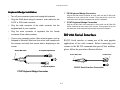
1
Disclaimer Welch Allyn® Data Collection, Inc. (d/b/a Hand Held Products) reserves the right to make changes in specifications and other information contained in this document without prior notice, and the reader should, in all cases, consult Hand Held Products to determine whether any such changes have been made. The information in this publication does not represent a commitment on the part of Hand Held Products. Hand Held Products shall not be liable for technical or editorial errors or commissions contained herein; not for incidental or consequential damages resulting from the furnishing, performance, or use of this material. This document contains proprietary information that is protected by copyright. All rights are reserved. No part of this document may be photocopied, reproduced, or translated into another language without the prior written consent of Hand Held Products. © 2001 Welch Allyn Data Collection, Inc. Web address: www.handheld.com All rights reserved. Statement of Agency Compliance Canadian Notice This equipment does not exceed the Class A limits for radio noise emissions as described in the Radio Interference Regulations of the Canadian Department of Communications. This device complies with part 15 of the FCC Rules. Operation is subject to the following two conditions: (1) this device may not cause harmful interference, and (2) this device must accept any interference received, including interference that may cause undesired operation. Le present appareil numerique n’emet pas de bruits radioelectriques depassant les limites applicables aux appareils numeriques de la classe A prescrites dans le Reglement sur le brouillage radioelectrique edicte par le ministere des Communications du Canada. FCC Class A Compliance Statement This equipment has been tested and found to comply with the limits for a Class A digital device, pursuant to part 15 of the FCC Rules. These limits are designed to provide reasonable protection against harmful interference when the equipment is operated in a commercial environment. This equipment generates, uses, and can radiate radio frequency energy and, if not installed and used in accordance with the instruction manual, may cause harmful interference to radio communications. Operation of this equipment in a residential area is likely to cause harmful interference, in which case the user will be required to correct the interference at his own expense. The CE mark on the product indicates that the system has been tested to and conforms with the provisions noted within the 89/336/ EEC Electromagnetic Compatibility Directive, EN55022:1998 Class A. For further information please contact: Hand Held Products (UK) Ltd. Dallam Court Dallam Lane Warrington, Cheshire WA2 7LT England Caution: Any changes or modifications made to this device that are not expressly approved by Hand Held Products may void the user’s authority to operate the equipment. Note: To maintain compliance with FCC Rules and Regulations, cables connected to this device must be shielded cables, in which the cable shield wire(s) have been grounded (tied) to the connector shell. i ii Table of Contents Chapter 4 Customer Service Chapter 1 Getting Started About This Manual 1-1 Chapter 2 Terminal Interfaces Keyboard Wedge Interface RS-232 Serial Interface USB Keyboard Interface 2-1 2-2 2-4 Chapter 3 Programming the Scanner Main Office 4-1 United Kingdom Office 4-1 Asia Pacific Office 4-2 Japan Office 4-2 Latin America Office 4-2 Chapter 5 Limited Warranty HHP SET™ 3-1 Data Editor 3-3 Bar Code Programming Menu Appendix A Interface Cable Converters A-1 3-5 Beeping Indications A-4 Programming Procedures 3-6 Keyboard Function Code Table A-5 Host Interface Selection 3-9 ASCII Input Shortcut A-6 Symbology Programming 3-10 Bar Code Command Menu A-7 Keyboard Interface Control 3-21 Sample Bar Codes A-8 Serial Interface Control 3-24 Bar Code System Command A-9 Wand Emulation Control 3-26 Operating Control 3-27 Condensed DataWizard 3-32 iii iv Getting Started 1. Getting Started About This Manual The IMAGETEAM™ 3220 Mid-Range Linear Imager replaces traditional laser bar code scanners with a high speed scanner at a lower cost. Equipped with a new generation light intensifier and optical design, the IT3220 has a high intensity aiming line and captures bar codes from as far away as 8 inches (20.3 cm). The unique decoding engine gives the IT3220 exceptionally fast and accurate scanning capabilities. Since the built-in flash memory makes the IT3220 field-upgradable, the scanner’s programming is always up-to-date. This User’s Guide provides installation and programming instructions for both the IT3220 and the VT3060B/3080B. Customer support and warranty information is also included. The VALUETEAM™ 3060B and 3080B CCD scanners are ideal entry level bar code readers. They offer excellent reading performance with the most often used terminals and PCs for point-of-sale or general purpose applications. Both the VT3060B and VT3080B have Flash Memory, are compact in size, are comfortable to use, and have been designed to take the punishment of daily use. Please verify the information displayed on the product label matches the information on the outer box label. If any difference is found, please contact your vendor immediately. Hand Held Products’ scanners are factory programmed for the most common terminal and communications settings. If you need to change these settings, programming is accomplished by either scanning the bar codes in this user’s guide or by using HHP SET™, a Windows-based utility that allows the user to perform on-screen configurations and software upgrades. 1-1 Getting Started Outer Box Label Outer Box Label IMAGETEAM MID - RANGE LINEAR IMAGER , UNIVERSAL INTERFACE Description VALUETEAM 80mm BAR CODE SCANNER , UNIVERSAL INTERFACE Description P/N : 3220-12 Model Number P/N : 3080B-12 Model Number S/N : A1210001 Serial Number S/N : A1220001 Serial Number N344 N344 Made in Taiwan Made in Taiwan Product Label Product Label N344 N344 Made in Taiwan Made in Taiwan P/N:3080B-12 S/N:A1220001 P/N:3220-12 S/N:A1210001 Complies with FCC Part 15 and Canadian ICES-003 Emission requirements. See User’s Manual for details Complies with FCC Part 15 and Canadian ICES-003 Emission requirements. See User’s Manual for details 1-2 Getting Started To use the HHP SET with the IT3220, the user must have a serial adapter cable and a power supply. Please refer to Chapter 3 “Programming the Scanner” to understand all details of HHP SET. You will find HHP SET has totally changed the traditional ways of managing your bar code reading device. The IT3220 and VT3060B/3080B models come with a main cable equipped with a RJ-45 phone plug, which can provide multiple host interface connections when combined with a host adapter cable. Please note that a separated cable adapter is needed to complete the cable connection for product installation. HHP SET HHP SET is a unique software utility that has been designed to operate under Microsoft Windows 95/98, Windows NT , and Windows 2000, and provides the following functions: ™ ® ® ® ® § User friendly on-screen configuration § Configuration download and upload § Program (Firmware) field upgrade § Check software revision § Full feature data editor 1-3 Getting Started 1-4 Terminal Interfaces 2. Terminal Interfaces Keyboard Wedge Interface The IT3220 and VT3060B/3080B scanners are easily configured to work with a variety of interfaces by installing the desired cable adapter and by programming the selected terminal interface. After identifying the communication interface you will use and obtaining the suitable interface adapter cable, you plug the RJ45 Phone Plug of the IT3220 or VT3060B/3080B main cable into the connector of the selected interface cable adapter. Please make sure the connector clicks into place securely. The keyboard wedge interface allows data transmission from the scanner to the host through the existing keyboard port as traditional keyboard input. 3220 Main Cable PC/AT, PS/2 Keyboard Wedge For the keyboard wedge solution, the scanner must work with the existing keyboard concurrently. If you want to link the scanner to a computer keyboard port without a PC/AT or PS/2 keyboard, please select “Emulate External Keyboard.” This selection instructs the scanner to perform the power-on handshaking and routine reply between computer and keyboard. Interface Cable Adapter All scanners have been preset to the “IBM PC/AT, PS/2 Keyboard Wedge” interface. If you need to change the host interface, please refer to the “Host Interface Selection” described in Chapter 3 to find your desired interface. The following paragraphs provide the installation of the most popular host interfaces. 2-1 Terminal Interfaces Keyboard Keyboard Wedge Installation F Plug the 5P DIN female connector of slave cable into the 5P DIN male connector of main cable of the scanner. Then connect the rest of the connectors to the computer keyboard port and PS/2 keyboard. § Turn off your computer system and unplug the keyboard. § Plug the RJ45 phone plug of scanner’s main cable into the F PC/AT or PS/2 cable converter. § Plug the male connector of keyboard into the female RSRS-232 Serial Interface connector of the cable converter. § PC/AT Keyboard Wedge Connection Plug the 6P Mini DIN male connector of slave cable into 6P Mini DIN female connector of main cable of the scanner. Then connect the rest of the connectors to the computer keyboard port and PC/AT keyboard. Plug the male connector of the cable converter into the keyboard port of your computer. § PS/2 Keyboard Wedge Connection Turn on your computer system. Open a text program, such as RS-232 Serial interface is among one of the most popular applications of bar code scanners. Before connecting your scanner to the RS-232 communication port of host machine, please follow the procedures illustrated below. Notepad or Microsoft Word and scan a bar code sample with the scanner and verify that correct data is displaying on the screen. Scanner Main Cable To Computer Keyboard Port Scanner Main Cable To Computer Keyboard To RS-232 Port RS-232 Serial Interface Connection PC/AT Keyboard Wedge Connection 2-2 Terminal Interfaces RSRS-232 Inter Interface Installation § Scanning the RS-232 interface bar code above configures the scanner’s serial parameters to 9600 Baud, 8 data bits, no parity, § Verify the RS-232 port (COM1 or COM2) available on your and 1 stop bit, no handshaking. computer system. Please note that the RS-232 settings of the host system must § Plug the RJ45 phone plug of the main cable into the RS-232 match the scanner’s RS-232 settings. cable adapter. § If you are in the Windows environment, you may use the ® § Plug the 9-pin or 25-pin D-sub connector of cable converter “Hyper Terminal” to test. into the desired serial port on your system. Standard RS-232 Pinouts § Attach the power outlet plug of the optional AC power adapter PIN-1: VCC (5V) PIN-2: TD PIN-3: RD PIN-4: NC PIN-5: GND PIN-6: NC PIN-7: CTS PIN-8: RTS PIN-9: VCC (5V) to the side power jack of the D-sub connector. You will hear the power-on beep twice to signal that the scanner is ready for bar code reading. Scan the “RS-232 Serial Interface” bar code to configure the scanner to perform the RS-232 serial interface operation. (-) (+) 9 Pin D-sub RS-232 Female Connector PIN-2: RD PIN-3: TD PIN-4: CTS PIN-5: RTS PIN-6: NC PIN-7: GND PIN-16: VCC (5V) PIN-25: VCC (5V) RS-232 Serial Interface (-) (+) Pin 25 D-sub RS-232 Female Connector 2-3 Terminal Interfaces USB Keyboard Interface The USB interface is one of the common standard peripheral interfaces for today’s computer system working under Windows 98 and Windows 2000 or above. § Make sure your computer has a USB port and the operating Scanning the following bar code will program for the USB interface. § Plug the RJ45 phone plug of the scanner main cable into the ® system is Windows® 98, Windows NT® 5.0, and Windows® 2000 or above. ® USB keyboard cable converter. § Plug the 4-pin USB Type A connector into the desired USB port of your computer. You will hear the power-on beep twice to signal that the power-on routine of the scanner is completed. § Whenever the scanner’s USB interface scanner is connected to any computer system for the first time, a string of “USB Manufacturer ID Message” will be prompted to register the scanner into the operating system. USB Keyboard Interface FuzzyScan Main Cable To Computer USB Port § Please scan the “USB Keyboard Interface” bar code to configure the scanner into USB keyboard interface mode. The scanner is now ready to use. USB Keyboard Interface Connection 2-4 Programming the Scanner 3. Programming the Scanner § Check Software Revision § Full-featured Data Editor There are two ways to configure the IT3220 or the VT3060/3080 – either using HHP SET or the programming bar codes in this user’s guide. ™ These beneficial features are accomplished through outstanding software design and on-board advanced flash memory ASIC. Via HHP SET HHP SET is a unique software utility designed to operate under Microsoft Windows 95, 98, NT or above. HHP SET offers a convenient and user-friendly way to program the scanner. ® HHP SET at A Glance ® Via Bar Code Programming Menu The bar code programming menu is designed for field programming convenience. Before you use the bar code programming menu, please take the time to review the command structure and various programming procedures. HHP SET Main Screen Host Interface Screen Data Editor Screen Bar Code Screen HHP SET The innovative HHP SET utility provides the following features: § User Friendly On-screen Configuration § Configuration Download and Upload § Program (Firmware) Field Upgrade (Flash) 3-1 Programming the Scanner Configuration Download and Upload You can retrieve (Upload) the configurations from the scanner or send (Download) new configurations to the scanner. Of course, duplicating preset configurations is as easy as 1-2-3. While you are asking HHP SET to do the “Download,” “Upload,” and “Diagnostic” with the scanner, HHP SET will ask you to use the scanner to scan the Host Link Command for initial handshaking with HHP SET and then perform your desired action. Program Field Upgrade Internal program (firmware) change or modification is only one step away via the Field Upgrade feature of the utility. HHP SET Host Link Check Software Revision You can use the Check Revision feature to check the software revision number, to verify if the communication between your scanner and host system is good, and to check the operation of the beeper and the indicator light. Software Installation You may download HHP SET from the IT3220 or VT3060B/3080B product pages from our web site at www.handheld.com. OnOn-screen Configuration Compared with the traditional configurations done via bar code menus, HHP SET provides a GUI interface that allows the user to easily configure the scanner. The Save feature allows the configuration to be saved as a file. The Convert feature consolidates all programmable parameters for a certain application and prints the configuration list. 3-2 Programming the Scanner § General Transmission Transmission Control The available parameters include “Preamble,” “Postamble,” “Suffix,” “Symbol ID and Data Length Transmission,” and “Transmission Time Control.” Data Editor Data Editor is an Artificial Intelligence-based Expert System used to format the scanned data before it is transmitted to the host system. The Data Editor Condensed Version has been embedded in the scanner. You gain access to desired Data Editor’s functions via scanning the menu’s bar code. The Full-Feature Data Editor is only available through HHP SET, which gives you the freedom of modifying the scanned data anyway you like, and allows you to integrate the scanner into any existing application. § Advanced Data Verification User can base the specific data format on the desired Bar Code Symbologies to select “Valid ASCII Domain,” “Valid Data Length Domain” and “Matched Data Value” to establish any desired filtering algorithm. This feature not only provides an on-scanner data filter without application software modification, but also reduces the error reading rate and improves data capture reliability. Data Format Editor The ultra powerful data editing functions provided by Data Editor are controlled by user-defined rules. Through independent rules, users can easily get the following functionality: § Field Oriented Data Formatter The Field Oriented Data Formatter allows user to flexibly divide scanned data by “Delimiter” or “Length.” To use with “Added Field” and “Transmission Sequence Arrangement” features, the user can implement “Insert,” “Delete,” “Replace,” “Re-organize” and other data editing capabilities beyond your imagination. 3-3 Programming the Scanner Application Example The bar code label is a 16-digit Code 39 that contains a 6-digit date code, a 6-digit serial number, and a 4-digit unit price (in that order). The scanner can do the following for you without software modification: § Configuration Procedure § Select “Using 1 Rule.” § Set “Applied Bar Code” to “Code 39.” § Set “Valid ASCII Range” to “Numeric.” § Select “Using Match 1.” Check the bar code to see if it is Code 39 or not. Reject any § Set “Matched Data “ to “99,” and set “Start Position” to “1.” codes that are not Code 39. § § Check the bar code content to see if it is numeric or not. Set “Field Divided By” of F1 to “Fixed Length” for “2.” Reject any codes that are not all numeric as invalid. § Set “Field Divided By” of F2 to “Fixed Length” for “4.” Check the first two digits to see if they match “99.” Reject any Set “Field Divided By” of F3 to “Fixed Length” for “6.” codes that do not match. Set “Field Divided By” of F4 to “Fixed Length” for “2” § Output each of the three fields followed by a “TAB.” § Then Data Editor assigns the remaining 2 digits as “Last The date code output should skip “99” and replaced it with Field (LF)” automatically. Please note that if the code 39 bar “AA.” code label is printed with “Check Digit,” the last field will have 3 digits. § The serial number output should be led with “S/N:.” § § The first 2 digits of unit price output should be skipped. § Set “Original Field” to “Divide scanned data into 4 fields.” Set ”Added Field” to “Insert 3 Added Fields.” The output sequence should be unit price, date code, and Set “AF1” (Added Field 1) to “AA.” serial number. Set “AF2” to “S/N:.” Set “AF3” to “TAB (Hex 09).” § Actual Bar Code label : 9 9 1 0 2 5 1 2 3 4 5 6 9 8 7 6 § § Desired Output : 76[TAB]AA1025[TAB]S/N:123456[TAB] Please use HHP SET to configure the full-feature Data Editor, and follow the procedures listed below. 3-4 Set “Transmission Sequence” to “LF,” “AF3,” “AF1,” “F2,” “AF3,” “AF2,” “F3,” and “AF3.” Programming the Scanner Bar Code Programming Menu System Command The System Command is the highest level bar code command that directs the scanner to perform immediate operations, such as entering programming mode (PROGRAM), exiting programming mode (EXIT), listing system information (SYSLIST), recovering to factory preset configurations (M_DEFAULT), and so on. Please note that all system commands will take a few seconds to complete the operations. The user must wait for the completion beeps before scanning another bar code. The bar code commands are specially designed Proprietary bar code labels that allow you to set the scanner’s internal programming parameters. There are System Command, Family Code and Option Code for programming purpose. Each programmable family and bar code command label is listed on the same page with major system commands. The detailed explanations and special programming flowchart are printed on facing or following pages. You can read the explanation and set the scanner concurrently. Family Code The Family Code is scanned to select the user desired programming family. More than one hundred programming families have been provided to meet any specific requirements. A supplemental bar code command menu incorporates the bar code command labels of System Command and Option Code. As you set the scanner, open the bar code command menu to find the option code page. You may scan the desired family code and option code to set scanner. If you want to change the programming family for multiple settings, you need only turn over the programming page to the find next desired programming family. Option Code The Option Codes is a set of bar code commands represented by “0–9,” “A–F,” and finishing selection (FIN). For most settings, you must select at least one option code following the family code selection to set the desired parameter for the selected programming family. 3-5 Programming the Scanner Programming Procedures As you scan the bar code command to select the desired parameters, this information is stored in the scanner’s internal Flash Memory ASIC or non-volatile memory. If you turn off the unit, the Flash Memory ASIC or non-volatile memory retains all programmed settings. 3-6 Programming the Scanner Program & End System List & Master Def Default ault Scan “PROGRAM” Scan “SYSLIST” Scanner lists the product information and Scanner enters programming mode, and inhibits all non-programming functions. revision number to host via selected host interface, then issues the completion beeping (3 short beeps). Scan “END” Scan “M_DEFAULT” Scanner exits programming mode, and stores all parameters in Flash Memory ASIC or non-volatile memory, Scanner returns all programmable parameters to factory preset configurations, then issues the completion beeping (3 short beeps). then issues the completion beeping (3 short beeps). Please note that the scanner will take 3-4 seconds to store parameters in internal Flash Memory ASIC or non-volatile memory after you scan the “END.” Please do not turn off the power before the completion beeping. It may destroy all configured parameters. 3-7 Programming the Scanner Selection Flow Diagrams EXAMPLE 1 EXAMPLE 2 Scan “PROGRAM” Scan One of Family Codes Scan One of Option Codes Scan “PROGRAM” Enter programming mode. Select one of desired Scan programming families. One of Family Codes (1st) Scan Several Option Codes several option codes of “Single” or “Multiple” Yes Repeat Selection programming families. of desired parameters. 1. Select one or several option codes of desired scans selection. (2nd) Scan One or Several Option Codes parameters. 2. If it’s necessary, scan Finish cycling selection. “FIN” to terminate (If necessary) option code selection. Yes Want to select another Repeat Selection Want to select another programming family? programming family? No Scan Select one of desired Select several option codes Cycling select one or desired parameters as Scan “FIN” If indicated Enter programming mode. No Scan “END” Exit programming mode. “END” 3-8 Exit programming mode. Programming the Scanner Host Interface Selection ♦ TERMINAL ID ♦ PROGRAM END(Exit) Family Code Selection Host Interface Selection ♦ US/EUROPEAN VERSION ♦ Parameter Selection Standard/TTL RS-232 serial interface 00 IBM PC/XT, 286/XT keyboard wedge interface (Full Size Din) 01 IBM PS/2, 25-30 series keyboard wedge interface (Mini Din) 02 IBM PC/AT, PS/1, PS/VP series keyboard wedge interface (Mini Din) u 03 PC/AT, PS/2 keyboard replacement interface (without external keyboard) 10 General Notebook PC keyboard wedge interface (PC/AT, PS/2 Compatibles) 03 General Notebook PC keyboard direct-link interface (without external keyboard) 14 APPLE ADB keyboard wedge interface 49 Standard TTL RS-232 serial wedge interface 50 Wand emulation interface 61 ® Host Interface Selection ® USB keyboard interface (for Microsoft Windows 98, 2000 and Apple iMac) C4 DOS/V keyboard wedge interface* A2 NEC PC-98xx keyboard wedge interface* A3 IBM ThinkPad keyboard direct-link interface (without external keyboard)* A6 ♦ JAPANESE VERSION ♦ § u FACTORY DEFAULT § For Notebook computer user, we suggest that the user try ID=10 first, then ID=14. § USB keyboard interface is only supported by Windows 98, Windows 2000 or above and Apple iMac system. § *Supported by Japanese Version only. Option Code All other interfaces are supported by both the US/Eurpoean and Japanese units. 3-9 Programming the Scanner User Defined Code ID This section allows the user to define and program a Code ID that is different from the Code ID default. To specify a one-character Code ID, scan in the 2-digit hex value for that character. Then scan “END”. The hex value can be determined by referring to the HEX/ASCII Reference Table on page A-6. To specify a two-character Code ID, scan the 2-digit hex values for each of the desired characters. Then scan “END.” If you only want to assign a one-character Code ID for UPC-E or EAN-8, scan the two-digit hex code for the desired character. Then Scan “FIN” and “END” bar codes. Note : To transmit the Code ID, you have to enable Code ID transmission in page 3-12. 3-10 Programming the Scanner Symbology Programming ♦ User Defined Code ID ♦ PROGRAM END(Exit) Family Code Selection Symbol ID : 1 character Symbol ID : 2 character Parameter Selection Option Code Option Code Code 128 (default=B) 00 Scan hex value (2 digits) UCC/EAN-128 (default=C) 01 Scan hex value (2 digits) UPC-A (default=A) 02 Scan hex value (2 digits) EAN/JAN/CAN-13 (default=F) 03 Scan hex value (2 digits) Codabar/NW-7 (default=D) 04 Scan hex value (2 digits) Code 39/Code 32 (default=G) 05 Scan hex value (2 digits) Code 93 (default=H) 06 Scan hex value (2 digits) Standard/Industrial 2 of 5 (default=I) 07 Scan hex value (2 digits) Interleaved 2 of 5 (default=J) 08 Scan hex value (2 digits) Matrix 2 of 5 (default=K) 09 Scan hex value (2 digits) China Postal Code (default=L) 10 Scan hex value (2 digits) German Postal Code (default=M) 11 Scan hex value (2 digits) IATA (default=O) 12 Scan hex value (2 digits) Code 11 (default=P) 13 Scan hex value (2 digits) MSI/Plessey (default=R) 14 Scan hex value (2 digits) UK/Plessey (default=S) 15 Scan hex value (2 digits) Telepen (default=T) 16 Scan hex value (2 digits) UPC-E (default=E0) 00 Scan hex value (2 or 4 digits) [FIN] EAN-8 (default=FF) 01 Scan hex value [2 or 4 digits] [FIN] § To determine the hex value for the “Character,” refer to the ASCII/HEX Table found in Appendix A. 3-11 Programming the Scanner Symbology Programming ♦ Code ID Transmission and Symbology Enable ♦ PROGRAM END(Exit) Family Code Selection Code ID Transmission Symbology Enable Remember to scan “FIN” to terminate this selection. But if you select the “ Automatic discrimination ,” Scanner will terminate this selection automatically. Parameter Selection Option Code Disable symbology ID transmission u 0 Enable prefix symbology ID transmission 1 Enable suffix symbology ID transmission 2 Enable both prefix and suffix symbology ID transmission 3 Automatic discrimination u 00 Code 128, UCC/EAN-128 01 UPC-A 02 UPC-E 03 EAN/CAN/JAN-13 04 EAN/CAN/JAN-8 05 Codabar/NW-7 06 Code 39/Code 32, HIBC 07 Code 2 of 5 Family, IATA 08 Code 93 09 Code 11 10 MSI/Plessey 11 UK/Plessey 12 Telepen 13 § If your application is reading known, limited bar code symbologies, you may increase the reading speed and decrease the reading error possibility by enabling those known symbologies only. Furthermore, to add the “Symbology ID” into the transmitted data is also helpful for applications to identify the specific symbology ID. For example, to enable UPC-A and Code 39 only scan the following bar codes: “PROGRAM,” “Symbology Enable,” “0,” “2,” “0,” “7,” “FIN” and “END.” § To further ensure fast, accurate readings, you can complete more complex configurations via full-feature Data Editor. To configure the full-feature Data Editor, you ® must use the HHP SET which is a Windows 95/98/NT based software utility specially designed for the scanner. 3-12 Programming the Scanner Symbology Programming ♦ Code 39/Code 32 Settings♦ Settings♦ PROGRAM END(Exit) Family Code Selection Code 39 Family Setting Code 39 Min. Length Parameter Selection Option Code Select Standard Code 39 u 0 Select Full ASCII Code 39 1 Select Code 32 (Italian Pharmaceutical) 2 Disable start/stop symbol transmission u 3 Enable start/stop symbol transmission 4 Disable Code 32 leading A transmission u 5 Enable Code 32 leading A transmission 6 Disable MOD 43 check digit verification u 7 Enable MOD 43 check digit verification 8 Disable check digit transmission 9 Enable check digit transmission u A FIN Default (04) u (2 digits) Minimum length Scan 2 digits from the option code chart in Appendix, then scanner will terminate this selection automatically. Code 39 Max. Length FIN Default (99) u (2 digits) Maximum length Scan 2 digits from the option code chart in Appendix, then scanner will terminate this selection automatically. 3-13 Programming the Scanner Symbology Programming ♦ Codabar/NWCodabar/NW-7 Setting ♦ PROGRAM END(Exit) Family Code Selection Codabar Setting Codabar Min. Length Parameter Selection Option Code Select Codabar standard format u 0 Select Codabar ABC format 1 Select Codabar CLSI format 2 Select Codabar CX format 3 Disable start/stop symbol transmission u 4 Enable ABCD/ABCD start/stop symbol transmission 5 Enable abcd/abcd start/stop symbol transmission 6 Enable ABCD/TN*E start/stop symbol transmission 7 Enable abcd/tn*e start/stop symbol transmission 8 Disable check digit verification u 9 Enable check digit verification A Disable check digit transmission B Enable check digit transmission u C FIN Default (04) u (2 digits) Minimum length Scan 2 digits from the option code chart in Appendix, then scanner will terminate this selection automatically. Codabar Max. Length FIN Default (99) u (2 digits) Maximum length Scan 2 digits from the option code chart in Appendix, then scanner will terminate this selection automatically. 3-14 Programming the Scanner Symbology Programming ♦ UPCUPC-A & UPCUPC-E Setting ♦ PROGRAM END(Exit) Family Code Selection UPC Family Setting Parameter Selection Option Code Select UPC without supplement digits u 0 Select UPC with only 2 supplement digits 1 Select UPC with only 5 supplement digits 2 Select UPC with 2/5 supplement digits 3 Disable UPC-E ex-pansion u 4 Enable UPC-E expansion 5 Disable UPC standardization u 6 Enable UPC standardization 7 Disable UPC numeric system 8 Enable UPC numeric system u 9 Disable UPC-A check digit transmission A Enable UPC-A check digit transmission u B Disable UPC-E check digit transmission C Enable UPC-E check digit transmission u D Disable UPC “leading 1” portion u E Enable UPC “leading 1” portion F § UPC-E & EAN-8 Expansion : Expand the 7-digit UPC-E and 8-digit ENA-8 to 12-digit UPC-A and 13-digit EAN-13. § UPC-A/E Standardization : Expand the 7-digit UPC-E and 12-digit UPC-A to 8-digit UPC-8 to 13-digit EAN-13 with 1 zero insertion. § UPC Lead 1 Numeric System : Enable to read UPC leading with the 1 numeric system, you must enable this option. WPC Selection (UPC/EAN/JAN/CAN) UPC-A UPC-E EAN/JAN/CAN-13 EAN/JAN/CAN-8 Basic Length 12 7 13 8 Disable Check Digit -1 -1 -1 -1 Disable Numeric System -1 -1 NC NC With 2-digit Addendum +2 +2 +2 +2 3-15 With 5-digit Addendum +5 +5 +5 +5 Enable Standardization +1 +1 NC NC Enable Expansion 0 +5 0 +5 Programming the Scanner Symbology Programming ♦ EAN/JAN/CAN & IATASetting ♦ PROGRAM END(Exit) Family Code Selection EAN/CAN/JAN Setting IATA Setting Parameter Selection Option Code Select EAN without supplement digits u 0 Select EAN with only 2 supplement digits 1 Select EAN with only 5 supplement digits 2 Select EAN with 2/5 supplement digits 3 Disable EAN-8 expansion u 4 Enable EAN-8 expansion 5 Disable EAN-13 check digit transmission 6 Enable EAN-13 check digit transmission u 7 Disable EAN-8 check digit transmission 8 Enable EAN-8 check digit transmission u 9 Disable ISBN/ISSN Conversion reading check u A Enable ISBN/ISSN Conversion reading check B Select 15-digit fixed length IATA checking u 0 Select variable length IATA 1 Disable check digit verification u 2 Enable check digit automatic verification 3 Enable S/N checking digit verification only 4 Enable CPN checking digit verification only 5 Enable CPN, Airline and S/N check digit verification 6 Disable start/stop symbol transmission u 7 Enable start/stop symbol transmission 8 Disable check digit transmission 9 Enable check digit transmission u A 3-16 Programming the Scanner Symbology Programming ♦ Code 2 of 5 Family & German Post Code Setting ♦ PROGRAM END(Exit) Family Code Selection Code 25 Setting Code 25 Min. Length Parameter Selection Option Code Select any Code 2 of 5 u Select Standard/Industrial 2 of 5 only Select Matrix 2 of 5 only Select Interleaved 2 of 5 only Select Interleaved 2 of 5 S Code only Select IATA only Select China Postal Code only 0 1 2 3 4 5 6 Disable check digit verification u Enable check digit verification 7 8 Disable check digit transmission Enable check digit transmission u Default (06) u 9 A FIN (2 digits) Minimum length Scan 2 digits from the option code chart in Appendix, then scanner will terminate this selection automatically. Code 25 Max. Length FIN Default (99) u (2 digits) Maximum length Scan 2 digits from the option code chart in Appendix, then scanner will terminate this selection automatically. German Postal Setting Disable u 0 Enable 1 § The scanner can decode almost all Code 2 of 5 symbologies automatically. But we recommend that you select only one kind of Code 2 of 5 for reading, or set limited maximum and minimum reading length for reading, because the encoding algorithm of Code 2 of 5 is not very robust. To decode all Code 2 of 5 automatically or to read variable length Code 2 of 5 will increase the error reading rate. 3-17 Programming the Scanner Symbology Programming ♦ Code 11 & Code 93 Sett Setting ♦ PROGRAM END(Exit) Family Code Selection Code 11 Setting Code 11 Min. Length Parameter Selection Option Code Select 1-check digit verification 0 Select 2-check digit verification u 1 Disable check digit transmission u 2 Enable 1-check digit transmission 3 Enable 2-check digit transmission 4 FIN Default (04) u (2 digits) Minimum length Scan 2 digits from the option code chart in Appendix, then scanner will terminate this selection automatically. Code 11 Max. Length FIN Default (99) u (2 digits) Maximum length Scan 2 digits from the option code chart in Appendix, then scanner will terminate this selection automatically. Code 93 Setting Code 93 Min. Length Disable check digit transmission u Enable check digit transmission 0 1 FIN Default (03) u (2 digits) Minimum length Scan 2 digits from the option code chart in Appendix, then scanner will terminate this selection automatically. Code 93 Max. Length FIN Default (99) u (2 digits) Maximum length Scan 2 digits from the option code chart in Appendix, then scanner will terminate this selection automatically. 3-18 Programming the Scanner Symbology Programming ♦ MSI/Plessey, Code 128 & UCC/EAN 128 Setting ♦ PROGRAM END(Exit) Family Code Selection MSI/Plessey Setting MSI/Plessey Min. Length Parameter Selection Option Code Select MOD 10 check digit u 0 Select MOD 10-10 check digit 1 Select MOD 11-10 check digit 2 Disable check digit transmission 3 Enable 1-check digit transmission u 4 Enable 2-check digit transmission 5 FIN Default (04) u (2 digits) Minimum length Scan 2 digits from the option code chart in Appendix, then scanner will terminate this selection automatically. MSI/Plessey Max. Length FIN Default (99) u (2 digits) Maximum length Scan 2 digits from the option code chart in Appendix, then scanner will terminate this selection automatically. Code 128/EAN-128 Setting Code 128/EAN-128 Min. Length Disable function code conversion u 0 Enable function code conversion 1 FIN Default (04) u (2 digits) Minimum length Scan 2 digits from the option code chart in Appendix, then scanner will terminate this selection automatically. Code 128/EAN-128 Max. Length FIN Default (99) u (2 digits) Maximum length Scan 2 digits from the option code chart in Appendix, then scanner will terminate this selection automatically. 3-19 Programming the Scanner Symbology Programming ♦ UK/Plessey & Telepen Setting ♦ PROGRAM END(Exit) Family Code Selection UK/Plessey Setting UK/Plessey Min. Length Parameter Selection Option Code Select UK/Plessey Standard Format u Select UK/Plessey CLSI Format 0 1 Disable Convert X to A-F u Enable Convert X to A-F 2 3 Disable check digit transmission u Enable check digit transmission Default (04) u Minimum length 4 5 FIN (2 digits) Scan 2 digits from the option code chart in Appendix, then scanner will terminate this selection automatically. UK/Plessey Max. Length FIN (2 digits) Default (99) u Maximum length Scan 2 digits from the option code chart in Appendix, then scanner will terminate this selection automatically. Telepen Setting Telepen Min. Length Select Telepen Numeric mode u Select Telepen Full ASCII mode 0 1 Disable check digit transmission u Enable check digit transmission 2 3 FIN (2 digits) Default (04) u Minimum length Scan 2 digits from the option code chart in Appendix, then scanner will terminate this selection automatically. Telepen Max. Length FIN (2 digits) Default (99) u Maximum length Scan 2 digits from the option code chart in Appendix, then scanner will terminate this selection automatically. 3-20 Programming the Scanner Keyboard Interface Control ♦ Keyboard Layout (Language) Setting ♦ PROGRAM END(Exit) Family Code Selection Keyboard Layout The “Universal Selection” is only for PC/AT, PS/VP, PS/2 and compatible ones in DOS or Windows environment which can perform unique output without Caps Lock on/off (Output Style) concern. All transmitted data will follow the original full ASCII form. You also need not worry about the upper/lower case control. Parameter Selection Option Code USA (QWERTY) u 00 France (AZERTY) 01 Germany (QWERTZ) 02 United Kingdom - UK (QWERTY) 03 Canadian French (QWERTY) 04 Spain (QWERTY) 05 Sweden/Finland (QWERTY) 06 Portugal (QWERTY) 07 Norway (QWERTY) 08 Latin America (QWERTY) 09 Italy (QWERTY) 10 Netherlands (QWERTY) 11 Denmark (QWERTY) 12 Belgium (AZERTY) 13 Switzerland-Germany (QWERTY) 14 Iceland (QWERTY) 15 Universal (only available for IBM PC/AT, PS/VP in MS DOS and Windows Mode) 99 § Please refer to the ASCII/HEX Table listed in Appendix A to determine HEX codes for characters, symbols, and functions to be used as premble or postamble. § To set preamble or postamble as function key output, you must enable the “Function Key Emulation” feature as listed in page 3-25 first. § Keyboard Interface Message String : Preamble Data Length Prefix Symbol ID Scanned Data Suffix Symbol ID Postamble Record Suffix 1-15 characters 2-3 digits 1 or 2 characters variable length 1 or 2 characters 1-15 characters 1 character 3-21 Programming the Scanner Keyboard Interface Control ♦ Record Suffix, Preamble, Postamble & Delay Setting ♦ PROGRAM END(Exit) Family Code Selection Record Suffix Parameter Selection None 0 RETURNu 1 TAB 2 SPACE 3 ENTER (Numeric Key Pad) 4 User defined character (1 character) Preamble Option Code 5, (00-7F) FIN None u [00-7F], [FIN] 1-15 characters Maximum 15-character input; scan “FIN” to terminate this selection. Postamble FIN None u [00-7F], [FIN] 1-15 characters Maximum 15-character input; scan “FIN” to terminate this selection. Character Frame Control FIN None u (2 digits) 1-99 msec. Scan 2 digits from the option code chart in Appendix, then scanner will terminate this selection automatically. Intermessage Delay FIN None u (2 digits) 1-99 (x5) msec. Scan 2 digits from the option code chart in Appendix, then scanner will terminate this selection automatically. Intercharacter Delay FIN None u (2 digits) 1-99 msec. Scan 2 digits from the option code chart in Appendix, then scanner will terminate this selection automatically. 3-22 Programming the Scanner Keyboard Interface Control ♦ Caps Lock Control & Emulation Setting ♦ PROGRAM END(Exit) Family Code Selection Caps Lock Control Function Key Emulation Parameter Selection Option Code “Caps Lock Off” State u 0 “Caps Lock On” State 1 Auto Detect (PC/AT, PS/2, Keyboard Replacement and DOS/V Machines only) 2 Enable ASCII 00-31 code as keyboard function code output u 0 Ctrl-Output 1 Refer to Appendix – Keyboard Function Code Table for details. Key Pad Emulation Upper/Lower Case Disable key pad emulation u 0 Enable numeric output as key pad (Num Lock On) output 1 Normal case (neglect the upper/lower case control) u 0 Inverse case (change all characters output to inverse case) 1 Upper case (force all characters output as upper case) 2 Lower case (force all characters output as lower case) 3 § Character Frame Control is used to adjust timing gap between bytes within one character data output by the scanner. Intercharacter Delay is a time delay between data characters output by the scanner. These two parameters are used to synchronize data communication when : 1) the data transmission speed is too fast, characters may be skipped; 2) multitasking operation system or host computers in a network may slow down the keyboard handling; 3) various notebook or desktop PC systems require different timing parameter settings. Please always add one extra unit as safety margin when adjusting these two parameters. § Intermessage Delay is a time delay between messages output by the scanner. Increasing this delay will help host applications process the incoming data on time. § The function of “Caps Lock Control” and “Key Pad Emulation” are only available for IBM PC/AT, PS/VP, PS/2 series personal computers and compatible machines. While selecting the other host interfaces, these selections don’t perform the above functions. § Please check the actual Caps Lock state in use while software application is running. If the Caps Lock state is off, select “Caps Lock Off” state, then the scanner will perform normal data transmission. If the Caps Lock state is on, select “Caps Lock On” state. Select “Auto Detect,” the scanner will perform special transmission handshaking without changing the status of Caps Lock switch. 3-23 Programming the Scanner Serial Interface Control ♦ Record Suffix, Handshaking & Time Out Setting ♦ PROGRAM END(Exit) Family Code Selection STX/ETX Control Parameter Selection Option Code Disable STX/ETX transmission u 0 Enable STX/ETX transmission 1 STX/ETX are two characters used to indicate the starting and ending of the total data frame transmitted via serial interface. Record Suffix None 0 CR (0DH) u 1 LF (0AH) 2 CRLF (0D0AH) 3 TAB (09H) 4 SPACE (20H) 5 EOT (04H) 6 7, (00-7F) User defined character (1 character) Preamble FIN None u [00-7F],[FIN] 1-15 characters Maximum 15-character input; scan “FIN” to terminate this selection. Postamble FIN None u [00-7F],[FIN] 1-15 characters Maximum 15-character input; scan “FIN” to terminate this selection. § Serial Interface Message String : STX Preamble Data Length 1 character 1-15 characters 2-3 digits Prefix Symbol ID Scanned Data Suffix Symbol ID Postamble 1 or 2 characters variable length 1 or 2 characters 1-15 characters 3-24 ETX Record Suffix 1 character 1 character Programming the Scanner Serial Interface Control ♦ Baud Rate & Data Frame Setting ♦ PROGRAM END(Exit) Family Code Selection Handshaking Protocol Baud Rate (BPS) Data Frame Parameter Selection None (free running mode) u 0 RTS/CTS (hardware handshaking) 1 ACK/NAK (software handshaking) 2 Xon/Xoff (software handshaking) 3 38.4K BPS 2400 BPS 0 4 19.2K BPS 1200 BPS 1 5 9600 BPS u 600 BPS 2 6 4800 BPS 300 BPS 3 7 8, None, 1 u 7, Space, 1 0 8 8, Odd, 1 7, Mark, 1 1 9 8, Even, 1 7, None, 2 2 A 8, Space, 1 7, Odd, 2 3 B 8, Mark, 1 7, Even, 2 4 C 8, None, 2 7, Space, 2 5 D 7, Odd, 1 7, Mark, 2 6 E 7 7, Even, 1 Time Out Control Option Code None 1 second 0 3 200 mseconds 2 seconds 1 4 500 mseconds u 5 seconds 2 User defined value (seconds) 5 6, (2 digits) § When the RTS/CTS Hardware Handshaking option is selected, the RTS (request to send) and CTS (clear to send) signals will be issued before normal data communication. This option is very helpful to ensure the reliability of data communication. § When the ACK/NAK Software Handshaking option is selected, the scanner waits for an ACK (acknowledge) or NAK (not acknowledge) from the host computer after each data transmission. If the NAK is received, the scanner will re-send the data until receiving ACK. § The Time Out Control is a pre-defined delay time for the scanner to wait for handshaking, acknowledgment or non-acknowledgment from the host computer. 3-25 Programming the Scanner Wand Emulation Control ♦ Output Polarity, Singal State, Margin/Module Time, etc.♦ etc.♦ PROGRAM END(Exit) Family Code Selection Output Polarity Parameter Selection Option Code High level (5Vdc) on Bar (low level on Space) u 0 Low level (0Vdc) on Bar (high level on Space) 1 Determine the output voltage level for both bar and space. Initial Signal State High Level (5Vdc) u 0 Low Level (0Vdc) 1 Determine the initial state of output voltage level. Margin Time Module Time 10 mseconds 30 mseconds 0 4 15 mseconds 50 mseconds 1 5 20 mseconds u 2 6 25 mseconds 100 mseconds Delay time before data transmission Extremely short Long 0 Short Code 39 Emulation 3 1 Time base of minimum narrow bar Medium u Narrow/Wide Ratio 3 2 1:2 u 0 1:2.5 1 1:3 2 Disable standard Code 39 emulation u 0 Enable standard Code 39 skip emulation 1 Enable standard Code 39 replace emulation 2 § [ Code 39 Skip ] : When this option is selected, all scanned data will be translated as Standard Code 39 wand emulation output. If any lower case characters are read, they will be translated to upper case characters. Any other characters that are not available in Code 39 symbology set will be skipped. § [ Code 39 Replace] : Any character not normally available in the standard Code 39 symbology set will be translated as Space. 3-26 Programming the Scanner Trigger Modes Alternative Mode When this operation mode is selected, the scanner keeps the light source of the scanner turned on and disables the infrared sensor before the pre-defined auto power off duration. Because you do not have to press the trigger frequently, it is very convenient for multiple scanning. After each good read, the auto power off timer counter is reset. After the scanner turns off the light source, you must press the trigger to turn on the light source again. If there is no scanning operation in pre-defined auto power off duration, the scanner turns off the light source and enables the infrared sensor after the pre-defined auto power off duration This section allows the user to select the trigger mode that is different from the Trigger Mode default. The operations of each trigger mode are described as below. Low Power Mode When this operation mode is selected, the scanner goes into idle state after scanning the bar code. You must press the trigger to wake up the scanner for operation. While the scanner is in the idle state, there is only maximum 500uA standby current for the entire reading device. It is very helpful for mobile data collection and application, which are concerned with power savings, but please keep a minimum of 120 milliseconds debounce time to stabilize the power transition. Presentation Mode When this operation mode is selected, the scanner flashes the light source of the scanner without using the trigger. If the scanner detects an image similar to a bar code, the scanner forces on the light source automatically and scans. If the scanner cannot detect a bar code, it resets the light source immediately to blinking. Adjusting the Pulse Driven Duty Cycle can change the frequency of the blinking. Manual Trigger Mode When this operation mode is selected, you must press the trigger to turn on the light source of the scanner before scanning the bar code. If you do not press the trigger, the light source will be turned off immediately. Please note that the scanner maintains standby current. You can adjust the debounce time to get faster triggering reading. Level Mode (Auto Power Off) Auto Trigger Mode (Continued Power On) When this operation mode is selected, the light source of the scanner is forced on for continued operation without pressing the trigger switch. This mode is convenient for high speed bar code reading. Toggle Mode (Repeat Reading) When this operation mode is selected, the scanner continues to turn on the light source of the scanner before a good read or pre-defined auto power off duration. If the scanner decodes a bar code successfully, it turns off the light source immediately. After the scanner turns off the light source, you must press the trigger to turn on the light source again. If there is no scanning operation performed during the pre-defined auto power off time, the scanner enters the idle state after the pre-defined auto power off duration. 3-27 The toggle mode is very similar to the Alternative Mode without the pre-defined auto power off duration concern. When this operation mode is selected, you must press the trigger to turn on the light source of the scanner. The scanner keeps the light source turned on until you press the trigger again. Programming the Scanner Scanning Tolerance 8.Diagnostic Mode (Test Reading) This operation mode is specifically designed for diagnostic purposes. When this operation mode is selected, the light source of the scanner is forced on without regard for other programmable parameters, such as double scan verification, redundancy, and so forth. (Print Quality Control) This parameter provides the user with a helpful tool to use when the printing quality of the bar code is poor. The regular image distortion acceptance of the scanner is designed to accept up to +/- 200% tolerance. With this feature you can increase the acceptable tolerance if you are using poorly printed or overly printed bar code labels. To reduce the error reading rate further, we also recommend that you limit the number of enabled symbologies to only those that you need to read, and to also limit the minimum and maximum reading of each enabled bar code symbology. 3-28 Programming the Scanner Operation Control ♦ Trigger Mode, Buzzer Tone, Scanning Tolerance ♦ PROGRAM END(Exit) Family Code Selection Operation Mode Buzzer Tone Adjust Scanning Tolerance (Printing Quality Control) Parameter Selection Option Code Low Power mode (Low Power triggering) 0 Manual trigger (External triggering) u 1 Level mode (Auto power off) 2 Alternative mode (Periodic power off) 3 Presentation mode (Pulse driven reading) 4 Auto trigger mode (Continued power on) 5 Toggle mode (Repeat reading) 6 Diagnostic mode (Test reading) 7 Buzzer tone - mute 0 Buzzer tone - low 1 Buzzer tone - medium u 2 Buzzer tone - high 3 Buzzer tone - extremely high 4 Good-read beep before data transmission u 5 Good-read beep after data transmission 6 Power-on beep u 7 No power-on beep 8 Regular (standard) printing quality u 0 Poor (critical) printing quality 1 Please note that if you select “Poor printing quality,” you should limit “Readable Bar Code Symbology” and “Minimum & Maximum Reading Length” of each symbology to avoid error reading. § The “Scanning Tolerance” is specially designed for the most popular symbologies, such as Code 39, UPC, and EAN. 3-29 Programming the Scanner Advanced Operation Control This section allows the user to program the following parameters for advance operation control. The definitions of each parameter are described below. Reread Delay This feature is designed to inhibit the scanner from reading the same bar code within a certain period of time. The time period can be programmed for immediate, short, medium, or long time out duration. Another selection is Force Verification which will not allow reading of the same bar code twice even after a very long duration. It should also note that this feature is not available if you have selected Low Power Mode, Manual Trigger Mode, Level Mode or Diagnostic Mode. Pluse Driven Duty The Pulse Driven Duty is designed to control the flashing frequency of the light source. For example, the 1/2 duty cycle means that the scanner turns on the light source at a time equal to 1/2 the duty cycle. Generally speaking, the higher scan rate will take the higher duty. Debounce Time Control Scan Voting Scan Voting is the number of times the same bar code is decoded before it is transmitted. This feature is useful when the bar codes being read are of poor quality. It should also be noted that this feature is not available if you have selected Low Power Mode, Manual Trigger Mode, Level Mode, or Diagnostic Mode. Auto Power Off Duration The Auto Power Off Duration is a pre-defined power off time out counter for Level Mode and Alternative Mode. You can adjust this parameter to meet your own application requirement. 3-30 In an effort to stabilize the sometime erratic signals that occur during power transition, a time delay is added. Increasing the debounce time decreases reading errors, but also reduces reading performance a little. Programming the Scanner Operation Control ♦ Reread Delay, Scan Voting ♦ PROGRAM END(Exit) Family Code Selection Reread Delay Scan Voting Auto Power Off Duration Pulse Driven Duty Debounce Time Control Dollar Sign Control Parameter Selection Option Code Disable Long time out duration 0 4 Immediate time out duration Force Verification 1 5 Short time out duration u 2 Medium time out duration 3 None 4 times 0 4 1 time 5 times 1 5 2 times u 2 3 times 3 Short (around 2 seconds) 0 Medium (around 3-4 seconds) 1 Long (around 5-6 seconds) 2 Extremely long (around 7-8 seconds) u 3 1/2 duty cycle u 0 2/3 duty cycle 1 3/4 duty cycle 2 4/5 duty cycle 3 None u 120 mseconds 0 4 20 mseconds 150 mseconds 1 5 50 mseconds 200 mseconds 2 6 100 mseconds 250 mseconds 3 7 Dollar sign output as “$” u 0 Dollar sign output as “Japanese Yen” 1 2 3-31 Programming the Scanner Condensed Data Editor ♦ Preamble, Postamble, Data Length & Symbol ID Trans. ♦ PROGRAM END(Exit) Family Code Selection Preamble Parameter Selection Option Code FIN None u 1-15 characters (use hex value for each character) [00-7F], [FIN] Maximum 15-character input; scan “FIN” to terminate this selection. Postamble FIN None u 1-15 characters (use hex value for each character) [00-7F], [FIN] Maximum 15-character input; scan “FIN” to terminate this selection. Data Length Transmission Disable u 0 Enable 2-digits data length transmission 1 If data length exceeds 99, 3-digit data length will be transmitted. Code ID Transmission Data Pass Control Disable Code ID transmission u 0 Enable prefix Code ID transmission 1 Enable suffix Code ID transmission 2 Enable both prefix and suffix Code ID transmission 3 Disable u 0 Enable 1 If data verifier is false, the original scanned bar code data will be transmitted. § The Data Editor is a very powerful, Artificial-Intelligence based data editing expert system provided specifically for the 3060B/3080B/3220 bar code scanners. Through the Data Editor, you can process the scanned data prior to transmitting in many ways, such as: Insert, Delete, Match, Verify, Replace, Reorganize, and Repeat Transmission. It also allow help you to arrange the transmission of scanned data to any specific format. § Due to the resources used by this system, the Full-feature Data Editor is only supported by HHP SET. Through HHP SET, all settings and configurations can be ® done on-screen, under Windows 95/98/NT environment. § A Condensed Version Data Editor is provided here in the manual and is utilized by scanning the programming bar codes. 3-32 Programming the Scanner Condensed Data Editor ♦ Data Formater ♦ PROGRAM END(Exit) Family Code Selection Symbology Selection 1st Insertion Parameter Selection Select one bar code symbology (2 digits) Select all bar code symbologies 00 automatic termination automatic termination Disable u FIN Hex value for each (2 digits) character, (FIN) position 1-3 characters to insert FIN Hex value for each (2 digits) character, (FIN) position 1-3 characters to insert FIN Hex value for each (2 digits) character, (FIN) position 1-3 characters to insert FIN Hex value for each (2 digits) character, (FIN) position 1-3 characters to insert 2-digits identified position; max. 3 insertion characters Disable u Enable 2-digits identified position; max. 3 insertion characters 3rd Insertion Disable u Enable 2-digits identified position; max. 3 insertion characters 4th Insertion 2nd Option Code FIN Disable u Enable 2nd Insertion Option Code Disable u Enable 2-digits identified position; max. 3 insertion characters § The Data Formatter is used to edit the scanned raw data prior to transmitting the data to the host computer or terminal. It allows you to select desired bar code symbologies for formatter control, and provides Multiple Position Insertion and Multiple Character Insertion (max three characters) in the identified position. § While the Data Formatter is enabled, it arranges only scanned data without Preamble, Postamble, STX, ETX, Data Length, Prefix/Suffix Symbolology ID or Record Suffix. All of the above programmable parameters perform the same function depending on your setting. § Regarding the “Bar Code Selection” and “Position Calculation” of data formatter, please refer to page 3-37 for details. § To determine the hex value for the “Character,” refer to the ASCII/HEX Table listed in Appendix A. 3-33 Programming the Scanner Condensed Data Editor ♦ Data Verifier Setting ♦ PROGRAM END(Exit) Family Code Selection Verifier Control Identified Data Length Parameter Selection Option Code 2nd Option Code FIN Disable u Select one bar code symbology (2 digits) automatic termination Select all bar code symbologies 00 automatic termination Disable u FIN (2 digits) Enable Determine the identified data length for verification. 1st Identified Character FIN Disable u (2 digits) Enable 2-digits checking position; 1 identified character 2nd Identified Character position FIN Disable u (2 digits) Enable [00-7F] position 2-digits checking position; 1 identified character 3rd Identified Character [00-7F] FIN Disable u (2 digits) Enable 2-digits checking position; 1 identified character [00-7F] position § The Data Verifier is used to provide advanced verification for error-free scanning and to work as an Embedded Data Transmitting Filter. § All data must conform to the Identified Bar Code Symbologies, Identified Data Length, and one to three Identified Characters in the checking position. Otherwise, the scanner will not transmit the data to the host computers or terminals, but will instead issue 3 long beeps for verification error and skip the scanned data. § The Data Verifier checks only scanned data without Preamble, Postamble, STX, ETX, Data Length, Prefix/Suffix Symbology ID or Record Suffix. § Regarding the “Bar Code Selection” and “Position Calculation” of Data Verifier, please refer to page 3-37 for details. § To determine the hex value for the “Character,” refer to the ASCII/HEX Table listed in Appendix A. 3-34 Programming the Scanner Condensed Data Editor ♦ Data Replacer Setting ♦ PROGRAM END(Exit) Family Code Selection Replacer Control 1st Replacement Parameter Selection Option Code FIN Disable u Select one bar code symbology (2 digits) automatic termination Select all bar code symbologies 00 automatic termination Disable u FIN (2 digits) Enable 2-digits identified position; 1 replacement character 2nd Replacement [ 00-7F ] position FIN Disable u (2 digits) Enable 2-digits identified position; 1 replacement character 3rd Replacement 2nd Option Code [ 00-7F ] position FIN Disable u (2 digits) Enable 2-digits identified position; 1 replacement character [ 00-7F ] position § The Data Replacer is used to edit the scanned raw data prior to transmitting the data to the host computers or terminals. It allows you to select desired bar code symbologies for replacer control, and provides Multiple Position Replcement in the identified position. § All data must conform to the Identified Bar Code Symbologies, and one to three Identified Characters in the identified position While the Data Replacer is enabled, it arranges only scanned data without Preamble, Postamble, STX, ETX, Data Length, Prefix/Suffix Symbology ID or Record Suffix. § Regarding the “Bar Code Selection” and “Position Calculation” of Data Replacer, please refer to page 3-37 for details. § To determine the hex value for the “Character,” refer to the ASCII/HEX Table listed in Appendix A. 3-35 Programming the Scanner Condensed Data Editor ♦ Data Organizer Setting ♦ PROGRAM END(Exit) Family Code Selection Organizer Control 1st Organization Parameter Selection Select one bar code symbology (2 digits) automatic termination Select all bar code symbologies 00 automatic termination Disable u FIN (2 digits) 2-digits identified character position; Transmit data before/after this position position FIN Disable u (2 digits) Enable 2-digits identified position; Transmit data before/after this position Include/Exclude Control 2nd Option Code FIN Disable u Enable 2nd Organization Option Code position Transmitted data excluding the data of identified positionu 0 Transmitted data including the data of identified position 1 Direction : 0 (Before) u 1 (After) Direction : 0 (Before) u 1 (After) § The Data Organizer is used to edit the scanned raw data prior to transmitting the data to the host computers or terminals. It allows you to select desired bar code symbologies for organizer control, and provides maximum two identified positions to send the data before or after. It also allows you to control the transmitted data including or excluding the data of identification position. Please refer to the application example listed in the next page for details. § While the Data Organizer is enabled, it arranges only scanned data without Preamble, Postamble, STX, ETX, Data Length, Prefix/Suffix Symbology ID or Record Suffix. § Reagrding the “Bar Code Selection” and “Position Calculation” of Data Organizer, please refer to the next page for details. § To determine the hex value for the “Character,” refer to the ASCII/HEX Table listed in Appendix A. 3-36 Programming the Scanner Select a Bar Code Symbology Application Example You can use the Condensed Data Editor for advanced transmission arrangement with one or all bar code symbologies. If you scan “00” to select all types, the scanner arranges all incoming data to meet your pre-defined format. If you want to select only one type bar code, please select one of the option codes listed below. § The bar code label is an all-numeric 16-digit Interleaved 2 of 5, which includes the information of 6-digit date code, 6-digit serial number, and 4-digit unit price, in that order. The data code always starts with a “9.” If a scanned bar code meets the above criteria, the data will be separated into three fields. Each field should end with a “TAB.” The first digit of the date code, which is a “9,” should be replaced with an “A.” The serial number should start with SN. The first 2 digits of the unit price should be skipped. UPC-E : 03 UPC-A : 02 EAN/CAN/JAN-8 : 05 EAN/CAN/JAN-13 : 04 Code 32 : 07 Telepen : 13 Code 128 : 01 UCC/EAN 128 : 01 Code 39 : 07 Code 93 : 09 Codabar/NW-7 : 06 Code 25 Family : 08 Code 11 : 10 UK/Plessey : 12 MSI/Plessey : 11 § Actual Bar Code read : 9 8 1 0 2 5 1 2 3 4 5 6 9 8 7 6 § Desired Output : A81025[TAB]SN123456[TAB]76[TAB] Position Calculation Programming Procedure [Data Formatter] If there is a 5-character input data string, refer to the following to calculate the actual position for insertion: X 00 X 01 X 02 X 03 [Important Notice] Please note that Condensed Data Editor will follow the preset working flow as below: X 04 05 Verifier [Data Verifier, Data Replacer, Data Organizer] X X X X X X X X X X 00 01 02 03 04 05 06 07 08 09 10 Formatter Replacer Organizer Consequently when you set the identified position in the Data Organizer, you must consider the inserted data that you have already set via Data Formatter. If there is an 11-character data string, please refer to the following to calculate the actual position for identification. X 3-37 Programming the Scanner [Data Verifier] A81025[TAB]SN123456[TAB]9876[TAB]. We still need delete the 98 from the string to get the desired output. § Scan “Program” to enter the programming mode. § Scan “Verifier Control” and set bar code symbology to “08” (Interleaved 2 of 5). [Data Organizer] § Scan “Identified Data Length” and set the length to “16.” § Scan “1st Organization” and set the identified position to “16,” then set the data transmission to “0” (before). § Scan “Organizer Control” and set bar code symbology to “08.” § Scan “1st Identified Character” and set the identified position to “00,” then set the identified character to “39” (Hex value for 9). The character position, which counts the added “SN” and TABs, is identified as 00, 01, 02,… so the 16th character is “9.” The [Data Formatter] § Scan “Formatter Control” and set bar code symbology to “08.” include/exclude control, which will be set to 0 for exclude in the last step of instructions below, determines that the “9” in the 16th position will not be sent. All of the characters before the 16th position will be transmitted. § Scan “1st Insertion” and set the identified position to “06,” then inserted characters to “09” (Hex value for TAB), “53” (Hex value for S), “4E” (Hex value for N). § Scan “3rd Insertion” and set the identified position to “16,” then inserted character to “09.” Finally, you must scan the “FIN” (Finish) code to terminate this selection. § Scan “2nd Organization” and set the identified position to “17,” which is “8,” in this case, then set the data transmission to “1” to transmit all of the characters after position 17. Whether position 17 gets transmitted along with the string is determined by the include/exclude control, which, in this case, will be excluded in the next step. [Data Replacer] [Include/Exclude Control] § Scan “Replacer Control” and set bar code symbology to “08.” § Scan Include/Exclude Control.” § Scan “1st Replacement” and set the identified position to “00,” then replaced character to “41” (Hex value for A). § Scan “0” for transmitted data excluding the data of identified position. At this point the data string is as following. § Scan “END” (Exit) to terminate the programming. § Scan “2nd Insertion” and set the identified position to “12,” then inserted character to “09.” Finally, you must scan the “FIN” (Finish) code to terminate this selection. 3-38 Customer Service 4. Customer Service For service in Europe, please contact your Hand Held Products’ representative or your local distributor. European Office Hand Held Products, Ltd. Hondsruglaan 87 D 5628 DB Eindhoven The Netherlands Telephone: Int+31 40 242 4486 Fax: Int+31 40 242 5672 Obtaining Factory Service Hand Held Products provides service for all its products through a service center located in Charlotte, North Carolina. To obtain warranty or non-warranty service, return the unit to Hand Held Products (postage paid) with a copy of the dated purchase record attached. In the United States, please contact the Hand Held Products’ Product Service Department at the address/telephone number listed below to obtain a Return Material Authorization number (RMA #). United Kingdom Office Hand Held Products (UK) Ltd. Dallam Court Dallam Lane Warrington Cheshire WA2 7LT United Kingdom Telephone: Int+44 (0) 1 925 240055 Or Int+353 1 216 0070 Fax: Int+44 (0) 1 925 631280 Or Int+353 1 295 6353 Main Office Hand Held Products Service Department 7510 East Independence Boulevard Charlotte, NC 28227 Product Service Department Telephone: (800) 782-4263 or (704) 568-0536 Fax: (704) 532-4191 4-1 Customer Service For service in Latin America, please contact your Hand Held Products’ representative (at the address that follows) or your local distributor. For service in Asia, please contact your Hand Held Products’ representative or your local distributor. Asia Pacific Office Latin America Office Hand Held Products 10/F Tung Sun Commercial Centre 194-200 Lockhart Road Wanchai, Hong Kong Telephone: Int+852-2511-3050 or 2511-3132 Fax: Int+852-251-1355 Hand Held Products 5117 Castello Drive Suite 1 Naples, FL 34103 Telephone: (941) 263-7600 Fax: (941) 263-9689 For service in Japan, please contact your Hand Held Products’ representative or your local distributor. Application Support Japan Office If you need assistance installing or troubleshooting your scanner, please call your distributor or the nearest Hand Held Products’ Application Support office listed below. You also can obtain assistance from our website at www.handheld.com. Hand Held Products Bon Marusan 8F 3-5-1 Kanda-Jinbocho Chiyoda-ku Toyko, 101, Japan Telephone: Int+81-3-5212-7392 Fax: Int+81-3-3261-7372 4-2 Customer Service North America: Telephone: (315) 685-2476 (8 a.m. to 6 p.m. EST) Fax number: (315) 685-4960 E-mail: [email protected] Europe: TelephoneEuropean Ofc: Int+31 40 242 4486 U.K. Ofc: Int+44 1925 240055 E-mail: [email protected] Asia: Telephone: Int+852-2511-3050 or 2511-3132 E-mail: [email protected] 4-3 Customer Service 4-4 Limited Warranty 5. Limited Warranty contacting HHP. In the event that the product is returned to HHP or its authorized service center within the Warranty Period and HHP determines to its satisfaction that the product is defective due to defects in materials or workmanship, HHP, at its sole option, will either repair or replace the product without charge, except for return shipping to HHP. Welch Allyn Data Collection, Inc., d/b/a Hand Held Products (“HHP”) warrants its products to be free from defects in materials and workmanship and to conform to HHP’s published specifications applicable to the products purchased at the time of shipment. This warranty does not cover any HHP product which is (i) improperly installed or used; (ii) damaged by accident or negligence, including failure to follow the proper maintenance, service, and cleaning schedule; or (iii) damaged as a result of (A) modification or alteration by the purchaser or other party, (B) excessive voltage or current supplied to or drawn from the interface connections, (C) static electricity or electro-static discharge, (D) operation under conditions beyond the specified operating parameters, or (E) repair or service of the product by anyone other than HHP or its authorized representatives. EXCEPT AS MAY BE OTHERWISE PROVIDED BY APPLICABLE LAW, THE FOREGOING WARRANTY IS IN LIEU OF ALL OTHER COVENANTS OR WARRANTIES, EITHER EXPRESSED OR IMPLIED, ORAL OR WRITTEN, INCLUDING, WITHOUT LIMITATION, ANY IMPLIED WARRANTIES OF MERCHANTABILITY OR FITNESS FOR A PARTICULAR PURPOSE. HHP’S RESPONSIBILITY AND PURCHASER’S EXCLUSIVE REMEDY UNDER THIS WARRANTY IS LIMITED TO THE REPAIR OR REPLACEMENT OF THE DEFECTIVE PRODUCT. IN NO EVENT SHALL HHP BE LIABLE FOR INDIRECT, INCIDENTAL, OR CONSEQUENTIAL DAMAGES, AND, IN NO EVENT, SHALL ANY LIABILITY OF HHP ARISING IN CONNECTION WITH ANY PRODUCT SOLD HEREUNDER (WHETHER SUCH LIABILITY ARISES This warranty shall extend from the time of shipment for the duration published by HHP for the product at the time of purchase (“Warranty Period”). Any defective product must be returned (at purchaser’s expense) during the Warranty Period to HHP’s factory or authorized service center for inspection. No product will be accepted by HHP without a Return Materials Authorization, which may be obtained by 5-1 Limited Warranty FROM A CLAIM BASED ON CONTRACT, WARRANTY, TORT, OR OTHERWISE) EXCEED THE ACTUAL AMOUNT PAID TO HHP FOR THE PRODUCT. THESE LIMITATIONS ON LIABILITY SHALL REMAIN IN FULL FORCE AND EFFECT EVEN WHEN HHP MAY HAVE BEEN ADVISED OF THE POSSIBILITY OF SUCH INJURIES, LOSSES, OR DAMAGES. SOME STATES, PROVINCES, OR COUNTRIES DO NOT ALLOW THE EXCLUSION OR LIMITATIONS OF INCIDENTAL OR CONSEQUENTIAL DAMAGES, SO THE ABOVE LIMITATION OR EXCLUSION MAY NOT APPLY TO YOU. All provisions of this Limited Warranty are separate and severable, which means that if any provision is held invalid and unenforceable, such determination shall not affect the validity of enforceability of the other provisions hereof. Limited Warranty Duration The Limited Warranty duration for the IT3220 is 2 years. The Limited Warranty duration for the VT3060/80 is 1 year. 5-2 Appendix A Appendix A Interface Cable Converters This chapter gives the most up-to-date description of scanner accessories, including various Host Interface Cable Adapters, Beeping Indications, and Keyboard Function Code Table. The following provides information about the most popular cable adapters, including: § § § § § § § § § § § Also, all necessary bar code commands are printed in the fold out of the back cover of this manual. A-1 PC/AT Keyboard Wedge Cable Converter PS/2 Keyboard Wedge Cable Converter General Notebook PC (PS/2) Direct Link Cable Converter USB Type A Direct Link Cable Converter APPLE ADB Keyboard Wedge Cable Converter IBM ThinkPad Keyboard Wedge Cable Converter IBM ThinkPad Direct Link Cable Converter NEC 98xx Keyboard Wedge Cable Converter RS-232 Serial Interface Cable Converter RS-232 Serial Wedge Cable Converter Wand Emulation Interface Cable Converter Appendix A Illustration Description Illustration PC/AT KB Wedge Cable Converter Description NEC 98xx Keyboard Wedge Cable Converter - Desktop PC/AT KB Wedge - 5P DIN Male & Female Connectors - 8P Mini-DIN M&F Connectors PS/2 KB Wedge Cable Converter IBM ThinkPad Direct Link Cable Converter - PS/2 KB Wedge - DOS/V KB Wedge - 6P Mini-DIN M&F Connectors - 6P Mini-DIN Male Connector USB KB Cable Converter IBM ThinkPad Keyboard Wedge Cable Converter - USB KB Direct Link - 4P USB Type A Male Connector - 6P Mini-DIN M&F Connectors Apple ADB Keyboard Wedge Cable Converter RS-232 Serial Cable Converter - RS-232 Peer-to-Peer Interface - 25P D-Sub Female Connector - Embedded Power Jack - 4P Mini-DIN M&F Connectors Apple PowerMac ADB Keyboard Wedge Cable Converter RS-232 Serial Cable Converter - RS-232 Peer-to-Peer Interface - 9P D-Sub Femal Connector - Embedded Power Jack - 4P Mini-DIN M&F Connectors A-2 Appendix A Illustration Description RS-232 Serial Wedge Cable Converter - 25P D-Sub M&F Connectors - Embedded Power Jack Notebook PS/2 Keyboard Direct Link Cable Converter - 6P Mini-DIN Male Connector Wand Emulation Interface Cable Converter - 9P D-Sub Female Connector A-3 Appendix Beeping Indications No. Descriptions Beeping Buzzer Tone 01 Internal or operation memory error Repeated beeps medium 02 Internal fatal error Repeated beeps medium 03 Beginning the normal operation 2 short beeps high + low 04 Entering the programming mode (Program) 3 short beeps high + low + low 05 Exiting the programming mode (End) 1 short beep medium 06 Completing to store the parameters 3 short beeps low + medium high 07 Starting the master default and group default 4 short beeps high medium + high + medium 08 Completing the master default and group default 3 short beeps low + high + low 09 Completing the system information listing 3 short beeps medium + high + medium 10 Good reading 1 short beep adjustable tone 11 Programming error (Invalid programming scan) 1 long beep medium 12 Scanning “FIN” to finish programming selection 2 short beeps medium + medium 13 Finishing the programming selection automatically 2 short beeps medium + medium 14 Data verifier checking error 3 long beeps medium + medium + medium 15 Memory buffer full 4 long beeps medium + medium + medium + medium 16 Time out warning 2 long beeps medium + medium 17 No CTS signal warning 1 long beep medium 18 Record over-size warning 1 long beep low A-4 Appendix A Keyboard Function Code Table No. ANSI ASCII 00 NUL 00H 01 SOH 02 Key Function No. ANSI ASCII Key Function RESERVED 16 DLE 10H F7 01H CTRL (Left) 17 DC1 11H F8 STX 02H ALT (Left) 18 DC2 12H F9 03 ETX 03H SHIFT 19 DC3 13H F10 04 EOT 04H CAPS LOCK 20 DC4 14H CTRL (Right) 05 ENQ 05H NUM LOCK 21 NAK 15H ALT (Right) 06 ACK 06H ESC 22 SYN 16H INS (Insert) 07 BEL 07H F1 23 ETB 17H DEL (Delete) 08 BS 08H + (Numeric Pad) 24 CAN 18H HOME 09 HT 09H TAB 25 EM 19H END 10 LF 0AH F2 26 SUB 1AH PAGE UP 11 VT 0BH F3 27 ESC 1BH PAGE DOWN 12 FF 0CH F4 28 FS 1CH UP 13 CR 0DH ENTER (Carriage Return) 29 GS 1DH DOWN 14 SO 0EH F5 30 RS 1EH LEFT 15 SI 0FH F6 31 US 1FH RIGHT To emulate the key functions above, program the scanner by using the corresponding ASCII hex value. For example, if you want to program in a suffix of a TAB, you would follow the directions for programming a suffix on page 3-21. For option code, scan “09” for a TAB. A-5 Appendix A ASCII Input Shortcut HEX/ASCII Reference Table To configure the user definable parameters of the scanner via the programming bar codes, you will be asked to scan your desired ASCII value in HEX form. You have to refer to the “HEX/ASCII Table” for details. 0 1 2 3 4 5 6 7 0 NUL DLE SPACE 0 @ P ` p 1 SOH DC1 ! 1 A Q a q 2 STX DC2 " 2 B R b r 3 ETX DC3 # 3 C S c s 4 EOT DC4 $ 4 D T d t 5 ENQ NAK % 5 E U e u 6 ACK SYN & 6 F V f v 7 BEL ETB ' 7 G W g w 8 BS CAN ( 8 H X h x § Scan family code – PREAMBLE to select this family. 9 HT EM ) 9 I Y i y § Refer to the Hex/ASCII Table, you will find the HEX value of “$” is 24. A LF SUB * : J Z j z B VT ESC + ; K [ k { § Scan the option code – 2 listed on the fold out back cover. C FF FS , < L \ l | D CR GS - = M ] m } E SO RS . > N ^ n ~ F SI US / ? O _ o DEL Example: If you want the scanned data output leading with a Dollar Sign, you have to set the “Preamble” to “$”. The configuration procedure is listed below for reference. § Scan the system command – PROGRAM listed on page 3-24 to enter programming mode. § Scan the option code – 4 listed on the fold out back cover. § Scan the system command – FIN (Finish) to terminate Preamble setting. Example : ASCII “A” → HEX “41”; ASCII “a” → “61” : High Byte of HEX Value : Low Byte of HEX Value § Scan the system command – End to exit the programming mode for normal operation. A-6 Appendix A Bar Code Command Menu Option Code : “0 – 9”, 9”, “A – F” F” 0 System Command 8 FIN (Finish) 4 1 C 9 END (Exit) 5 2 D A SYSLIST 6 3 (System List) E B (Master Default) M_DEFAULT 7 F A-7 Appendix A Sample Bar Codes Codabar A13579B Code 39 BC321 Interleaved 2 of 5 1234567890 Code 128 Code 128 Code 93 123456-9$ Matrix 2 of 5 6543210 Code 2 of 5 123456 EAN 13 9 780330 290951 UPC-A 0 123456 7890 5 A-8 Appendix A Bar Code System Command Bar Code System Command Set Set System Information List (SYSLIST) PC/AT, PS/2 Keyboard Wedge USB Keyboard Interface Keyboard Replacement Factory Default Setting (M_DEFAULT) RS-232 Serial Interface HHP SET Host Link A-9 4619 Jordan Road P.O. Box 187 Skaneateles Falls, New York 13153-0187 3060/80/3220/UG Rev A