1
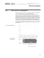
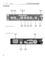
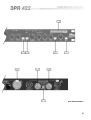
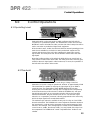
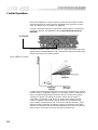
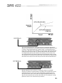
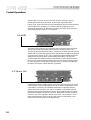
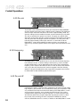
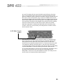
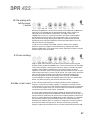
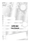
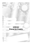
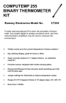
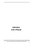
DPR 422
User Manual
1
V 1.0
JMK
1 April 1997
This equipment has been tested and found to comply with the following European and
international Standards for Electromagnetic Compatibility and Electrical Safety:
Radiated Emissions (EU):
RF Immunity (EU):
Mains Disturbance (EU):
Electrical Safety (EU):
Radiated Emissions (USA):
Electrical Safety (USA):
Electrical Safety (CAN):
EN55013
(1990) Associated Equipment
EN50082/1
(1992) RF Immunity, Fast Transients ESD
EN61000/3/2
(1995)
EN60065
(1993)
FCC part 15 Class B
UL813/ETL
(1996) Commercial Audio Equipment
UL813/ETLc
(1996) Commercial Audio Equipment
IMPORTANT SAFETY INFORMATION
DO NOT REMOVE COVERS. NO USER SERVICEABLE PARTS INSIDE, REFER SERVICING TO QUALIFIED
SERVICE PERSONNEL. THIS EQUIPMENT MUST BE EARTHED.
IT SHOULD NOT BE NECESSARY TO REMOVE ANY PROTECTIVE EARTH OR SIGNAL CABLE SHIELD
CONNECTIONS TO PREVENT GROUND LOOPS. ANY SUCH DISCONNECTIONS ARE OUTSIDE THE
RECOMMENDED PRACTISE OF BSS AUDIO AND WILL RENDER ANY EMC OR SAFETY CERTIFICATION
VOID.
For continued compliance with international EMC legislation ensure that all input and output cables are wired
with the cable screen connected to Pin 1 of the XLR connectors and/or the jack plug sleeve. The input XLR Pin 1
and the side-chain input jack socket sleeve are connected to the chassis via a low value capacitor, providing
high immunity from ground loops whilst ensuring good EMC performance.
Please read
We have written this manual with the aim of helping installers, sound engineers and musicians alike to get the
most out of the DPR-422. We recommend that you read this manual, particularly the section on installation,
before attempting to operate the unit.
The manual is split into two main sections. The first deals with quick reference information, regarding the
functions and operation of the unit, while the second covers a more general background to use and application
of the DPR-422.
We welcome any comments or questions regarding the DPR-422 or other BSS products, and you may contact us
at the address or World Wide Web site given in the warranty section.
2
Contents
Contents
1.0
Mechanical installation
5
2.0
Mains Power Connection
Mains Power
6
6
3.0
Introduction
7
4.0
Unpacking
7
5.0
5.1
5.2
5.3
5.4
Audio Connections
Main Inputs
Main Outputs
Side Chain Inputs
Side Chain Outputs
10
10
10
11
12
6.1
6.2
6.3
6.4
6.5
6.6
6.7
6.8
6.9
6.10
6.11
6.12
6.13
Control Operations
Operating Level
Threshold
Ratio
Attack
Release
AUTO
Stereo Link
Gain
Channel In
De-ess
Frequency
De-ess HF
Side Chain Listen
13
13
13
14
15
15
16
16
17
17
18
18
18
19
7.1
7.2
7.3
7.4
Meter displays
Input Meter
Below Threshold Meter
Gain Reduction Meter
Output Meter
20
20
20
21
21
2.1
6.0
7.0
3
Contents
8.0
General Applications
The need for Gain control
Compressors and Limiters
The effect of Compression and
Limiting on sound
De-essing
Broadband De-essing
HF De-essing
22
22
23
Operation and applications
Compression
De-essing
HF De-essing
HF De-essing with full Dynamic
control
Peak Limiting
Side chain insert
26
26
26
27
10.0
Troubleshooting
29
11.0
Warranty Information
30
12.0
Specifications
31
13.0
Glossary
32
Index
34
User Notes
36
8.1
8.2
8.3
8.4
8.5
8.6
9.0
9.1
9.2
9.3
9.4
9.5
9.6
Spare Parts Information
4
24
25
25
25
27
28
28
Mechanical Installation
1.0
Mechanical installation
A vertical rack space of 1U (1¾" / 44.5 mm high) is required, with a depth of
190mm. Ventilation gaps are unnecessary (See Figure 1.1).
If the unit is likely to undergo extreme vibration through extensive road
trucking and touring, it is advisable to support the unit at the rear and/or sides
to lessen the stress on the front mounting flange. The necessary support can
generally be bought ready-built as a rack tray, or the DPR-422 can be mounted
between other units. Damage caused by insufficient support is not covered in
the warranty. To prevent damage to the paintwork on the front panel, always
use protective plastic cups or washers underneath the rack mounting bolts.
As with any low-level signal processing electronics, it is best to avoid mounting
the unit next to a strong source of magnetic radiation or heat, such as a high
power amplifier.
Fig 1.1 Unit dimensions.
Fig 1.2 Rack
dimensions.
5
Mains Power Connection
2.0
Mains Power Connection
2.1 Mains Power WARNING! THIS APPLIANCE MUST BE EARTHED.
The DPR-422 must always be connected to a 3-wire earthed AC outlet. The
rack framework must also be connected to the same grounding circuit. The
unit must NOT be operated unless the power cables' EARTH (ground) wire is
properly terminated - this is important for personal safety as well as for proper
control over the system grounding.
The wires in the mains lead are colour coded in accordance with the following
code.
Green and Yellow......Earth
Blue......Neutral
Brown......Live
Those units supplied to the North American market will have an integral
moulded 3 pin connector which is provided to satisfy required local standards.
IMPORTANT: The DPR-422 is designed to use 50/60Hz AC power in one of
the two voltage ranges, selectable with the mains voltage selector switch on
the rear of the unit. It is vital that the position of this switch is checked BEFORE
initial power up to ensure that it matches the local mains supply. Acceptable
input AC supply voltages range from:
115V switch position
230V switch position
-
90V to 132V
190V to 265V
The application of voltages outside these ranges may cause permanent damage
or erratic operation of the unit, and will invalidate the warranty.
IMPORTANT: The mains fuse carrier on the rear of the unit must be fitted with
the correct type and rating of fuse, depending on the position of the mains
voltage selector switch:
115V switch position
230V switch position
-
T315mA fuse
T200mA fuse
In the unlikely event of the mains fuse failing without good reason,
DISCONNECT THE UNIT FROM THE MAINS SUPPLY, and always replace
with the appropriately rated fuse (as specified above) for continued protection
against damage and fire.
Note: For USA and Canadian users, the replacement fuse must be of an
identical UL rated type fuse for continued compliance with safety standards.
6
Introduction
Unpacking
3.0
Introduction
The BSS DPR-422 compressor, de-esser has been designed in response to the
demand for a versatile, cost effective two channel unit which maintains the
proprietary, audibly transparent, subtractive VCA technology as used in the
well established BSS DPR-402 unit. The provision of a separate, balanced
insert input and output per channel minimises the possibility of interference
that other units with unbalanced connections may suffer from.
To aid the integration of the DPR-422 into the widest range of systems, a rear
panel switch allows the operating level of unit to be set to either +4dBu, to suit
professional or -10dBV to suit semi-professional equipment.
The compressor section allows full control over all the normal parameters, and
offers AUTO time constants for general purpose use. The side chain insertion
point allows for the patching of external filters to provide dynamic tonal
modification for special treatments or special effects. Metering and monitoring
is comprehensive and easily interpreted. The full compressor operating range is
displayed on a two part meter, indicating both signals below threshold and
actual gain reduction. The arrangement of these two meters provides a highly
intuitive view of the modification being applied to the input signal.
Two modes of de-essing are available on the DPR-422. A dedicated broadband
de-esser allows wide band sibilance control simultaneously, and
independently from the main compressor. Operation is indicated on two
separate LED indicators, and therefore does not compromise the metering for
the main compressor. For highly critical de-essing applications, the compressor
section can be switched to operate on selected high frequencies only with full
control over the ratio, attack and release.
The output signal is continuously monitored on the output level meter but
depressing the INPUT METER switch allows measurement of the input signal to
aid level matching. Provision is also provided for listening to the de-esser filters
and any external side-chain equipment to aid accurate setting.
4.0
Unpacking
As part of the BSS system of quality control, we check every product carefully
before packing to ensure that it reaches you in flawless condition.
Before you go any further, please check the unit for any physical damage and
retain the shipping carton and all relevant packing materials for use, should the
unit need returning.
In the event that damage has occurred, please notify your dealer immediately,
so that a written claim to cover the damages can be initiated. Check out
section 10.0; warranty section, for more info on the warranty, and also to
record your dealer details.
7
The DPR-422
Fig 4.1 Front Panel
Fig 4.2 Rear Panel
8
All numbers in bubbles refer to Section numbers.
9
Audio Connections
5.0
Audio Connections
5.1 Main Inputs
There are 2 input sockets on the rear panel of the 422, Inputs 1 and 2. Each is
electronically balanced on standard 3 pin female XLRs at an impedance
greater than 10k Ohms. The ‘HOT, + or in phase’ connection is to pin 2 and
the ‘COLD, -, or out of phase’ connection is to pin 3. Pin 1 is internally
connected to the chassis earth via a low value capacitor. This ensures freedom
from ground loops whilst allowing good EMC performance. The screen of the
input cable should be connected to pin 1 to ensure that EMC regulations are
being met, and the cable shield ground should also be connected to the
equipment which is providing the input signal.
Fig 5.1
When feeding the DPR-422 from unbalanced sources, connect the signal
conductor to pin 2 and the cable screen to pins 1 and 3. Transformer isolated
inputs are available as a dealer fitted option.
Fig 5.2
5.2 Main Outputs
Fig 5.3
10
The output signals are electronically balanced and fully floating on 3 pin male
XLRs. Full headroom is available into any load of 600 Ohms or greater. The
signal ‘HOT, +, or in phase’ signal is to pin 2, the ‘COLD, -, or out of phase’
signal is to pin 3, with pin 1 being connected directly to the chassis.
When using the DPR-422 to drive unbalanced inputs, best performance is
usually obtained by connecting the DPR-422s ‘+’ signal to the equipment
signal pin and the ‘-’ signal to the equipment shield.
Fig 5.4
The DPR-422 shield should normally be connected to the equipment shield,
preferably at the equipment end. Transformer isolated outputs are also
available as a dealer fitted option.
5.3 Side Chain
Inputs
The side chain insert inputs are electronically balanced via stereo 5mm jack
sockets at an impedance greater than 100k Ohms. The ‘HOT, +, or in phase’
connection is to the jack plug tip, the ‘COLD, - or out of phase’ connection to
the ring. The shield is internally connected to the chassis earth via a low value
capacitor. This ensures freedom from ground loops whilst allowing good EMC
performance. The screen of the cable must be connected to the jack plug
shield to ensure continued compliance with EMC regulations. The cable shield
ground should be connected to the equipment which is providing the input
signal.
Fig 5.5
When feeding the DPR-422 from unbalanced sources, connect the signal
conductor to the jack plug tip and the cable screen to the plug ring and shield.
Fig 5.6
11
Audio Connections
5.4 Side Chain
Outputs
The side chain uses a quasi-balanced ‘ground compensated’ output. When
connected to a balanced input, interference rejection equivalent to a fully
floating output can be obtained. Full headroom is available into any load of 2k
Ohms or greater. The signal ‘HOT, +, or in phase’ signal is to the jack plug tip.
The ‘COLD, -, or out of phase’ signal is to the ring with the shield being
connected directly to the chassis.
Fig 5.7
Connection to unbalanced inputs may be done by connecting the tip to the
signal input and the ring to the input shield. The DPR-422 shield may or may
not be connected to the equipment shield at the equipment end.
Fig 5.8
12
Control Operations
6.0
Control Operations
6.1 Operating Level
Setting this switch on the rear panel to +4dBu configures the DPR-422 for
connection in a professional system. The THRESHOLD control and OUTPUT
METER will read in dB relative to 0dBu, and the side chain insert points will be
set for connection to professional signal level equipment.
With the switch set to -10dBV, the DPR-422 shifts its internal operating point to
make it more suitable for connection to semi-professional equipment. The
internal gain structure of the unit is also optimised for these lower overall
signal levels. The insert points will also be shifted to match that of the main
signal path.
Note that in either position of the switch the DPR-422 has an overall gain of
unity (with the GAIN control set to 0dB). The insert points also have unity gain
relative to the main signal path in either mode and, of course, the operation of
the DPR-422 is the same in either mode.
6.2 Threshold
Gain reduction in the DPR-422 is achieved using a Voltage Controlled
Attenuator (VCA) with a range or operational ‘window’ of approximately 35dB.
This means that it is capable of reducing the input signal by up to 35dB or
nearly 60 times. The GAIN REDUCTION METER displays this window,
showing how much attenuation is being used. The signal level corresponding
to the lower boundary of this window is called the THRESHOLD, and input
signals below this level do not cause gain reduction. When the input level
exceeds the threshold, the gain reduction will kick in. The amount of gain
reduction or ‘compression’ produced is directly proportional to the amount by
which the input signal level exceeds the threshold.
The maximum gain reduction available is set by the circuitry at a level 35dB
above the threshold. The THRESHOLD control adjusts the threshold relative to
the input signal in order to set the compressor to the required amount of gain
reduction. For example, if the average input is +12dBu and the THRESHOLD
control is set to -10dBu, then the top 22dB, [12-(-10)]=22dB, of the signal can
be compressed. The THRESHOLD control is adjustable from -30dBu to over
+20dBu.
13
Control Operations
When the THRESHOLD control is set fully clockwise to the position marked
OUT the threshold can not be reached, regardless of the input level, and the
signal will always reach the output uncompressed.
How the compressor performs on signals above the threshold is controlled by
the RATIO, ATTACK, and RELEASE controls (see the following sections for
more info.)
6.3 Ratio
The effect of the ratio control can be shown on a graph which plots input level
against output level (see figure 6.1). This clearly shows that below threshold the
DPR-422 acts purely as a linear amplifier.
Fig 6.1 Effect of ratio
In applications where gentle compression is required, it is beneficial to change
from the linear to compression region in a very gradual manner, rather than the
more conventional abrupt manner as shown above. The DPR-422 has been
configured so that for low settings of the ratio control and low levels of
compression, the transfer is soft, and for increasing ratio settings and high
levels of compression the transfer becomes harder. This ‘progressive knee’
gives inaudible compression for low levels of ratio and gain reduction, whilst
allowing harder compression for effective limiting and extreme control when
required. This feature is exclusive to BSS equipement, and is why the DPR-422
doesn't require a 'soft knee' control as all other compressors do.
14
6.4 Attack
This control determines how quickly the DPR-422 compressor responds to
signals once the threshold is exceeded and provides a range of times from 50us
to 100ms. For transient signals (very sudden 'spikes' in the signal that last a
short time), a fast attack time is desirable. For other types of program material a
slower time will be more useful. It is always better to start with a slower time,
and progressively speed up the response as necessary, since too fast a time
may cause distortion of the sound, especially with signals that contain a lot of
low frequencies. The times printed around the control refer to the approximate
time taken for the signal to be reduced by two thirds of the ultimate reduction.
6.5 Release
Release determines how quickly the compressor returns to normal gain
following a transient over the threshold. The setting of the release time can be
varied from 5ms to 2s, and is very much dependant on program type. The
times printed around the control refer to the approximate time taken for the
signal to be recovered to 90% of from the initial level. The setting of a wrong
speed will result in one of the following conditions:
15
Control Operations
If set too fast, the overall volume level will jump up and down, exactly
following the peaks above threshold, producing an unpleasant effect.
If set too low, quiet parts of the program immediately following loud transients
will be subjected to ‘breathing’ or ‘pumping’ effects caused by the VCA
releasing its attenuation (or effectively increasing the system gain) during the
quiet program period, when it is not required.
6.6 AUTO
This feature of the DPR-422 is provided to overcome some of the conflicting
setting requirements associated with the attack and release controls. It is
accessed by pressing the AUTO button, whereupon the DPR-422 automatically
adjusts itself to provide the required attack and release time settings, dependant
on the program content. AUTO uses a combined program related attack time
setting and a two part program related release time setting. The two part
program dependant release provides a fast release to restore below threshold
gain as soon as the transient has passed, and a much longer following release
to avoid rapid gain change effects. Note that once AUTO has been selected,
the attack and release controls become inoperative.
6.7 Stereo Link
Depressing this button enables the two channels of the DPR-422 to be used in
a stereo system, and ensures that there will be no stereo image shifting under
compression or de-essing. The STEREO LINK switch couples the detector
outputs from both channel 1 and channel 2 together, so that both channels
respond equally to the largest signal present. This combined signal is passed
through the THRESHOLD, RATIO, ATTACK, RELEASE and AUTO controls of
channel 1 and is then applied to BOTH the channel 1 and channel 2 VCAs.
Independent operation of the channel GAIN controls is maintained in link
mode, and they must BOTH be set appropriately.
16
When linked, the channel 1 below threshold meter shows the combined
channel 1 & 2 signal. The channel 2 below threshold meter shows only signals
on channel 2, this provides a visual indication that there is a signal on channel
2. Note that the level on the channel 2 meter can be changed with the channel
2 threshold control, although along with the channel 2 de-ess, ratio, attack,
release and auto controls, this has no effect on the operation of the unit. If
desired, the channel 2 threshold control can be set to OUT and there will then
be no signal on the channel 2 below threshold meter. The gain reduction
meters for both channels indicate the same value, as controlled from channel
1. The output meters indicate the level on their respective channel.
If the DPR-422 is being used in either broadband or DE-ESS HF mode, it is
important that the FREQUENCY control for both channels are in the same
position.
6.8 Gain
As compression is a gain reducing process, the output signal level will often be
less than the input. The GAIN control is provided to restore the output signal to
the desired operating point, and provides a calibrated range of ±20dB relative
to the input signal. The facility for gain loss provided by this control can be
used, when required, to restore the compressed signal to a point lower than the
input signal and might be useful, for example, when connecting the output to a
high sensitivity input on a following piece of equipment.
6.9 Channel In
When the CHANNEL IN switch is in the out, non illuminated position, all DPR422 functions are bypassed and the input is connected directly to the output
via a relay. This condition also occurs when the power is off, and ensures that
the signal is passed through the unit in the case of a power or fuse failure.
When the switch is pressed in, the processed signal is passed to the output.
In bypass mode, the input is still connected to all of the DPR-422 circuitry, so
that all of the required facilities can be selected and set up. This, in
conjunction with the OUTPUT METER and INPUT METER SWITCH, provides a
powerful tool for comparing processed signals prior to operating the bypass
switch and going ‘live’.
17
Control Operations
6.10 De-ess
The DE-ESS control determines how much gain reduction the BROADBAND
de-esser applies to the signal when a sibilant sound is detected. The maximum
amount of gain reduction available in this mode is approximately 20dB. The
dynamic settings for the broadband de-esser are set automatically by the DPR422 and are optimised for general vocal work. The green and yellow LEDs
above the de-ess control provide a simple indication of the degree of de-essing,
with the green LED indicating the start of the operation, and the yellow LED
indicating approximately 15dB of gain reduction. In association with the
FREQUENCY control the broadband de-esser provides a very simple and
effective way of treating general sibilant vocal signals, when processed on their
own.
6.11 Frequency
The FREQUENCY control should be set to coincide with the lowest frequency
in the sibilance sound. To aid the setting of the frequency control, the SIDE
CHAIN LISTEN switch can be depressed and the onset of the lowest sibilant
frequency at the output of the selection filter can then be heard. Note that this
will only be the case if the de-ess HF mode is engaged. If the filter is being
setup for use by the broadband de-esser, temporarily engage de-ess HF mode
to enable SIDE CHAIN LISTEN to pass the filter signal.
6.12 De-ess HF
Depressing this button causes the main compressor to be used as a high quality
high frequency (HF) de-esser. As in broadband de-essing, the compressor is still
only activated when frequencies above the setting of the FREQUENCY control
are encountered. However, once activated, the DPR-422 will only reduce
(compress) those signals that caused the activation. In other words, the DPR422 behaves rather like a program dependant high frequency filter. To allow
fine control of the de-essing, the main compressor THRESHOLD, RATIO,
ATTACK, RELEASE and AUTO controls, in addition to the FREQUENCY control
18
are used. The setting of these controls should broadly follow the directions
given in the respective parts of this manual. The below threshold and gain
reduction meters are used to monitor the operation of the HF de-esser. The DEESS control, active and high LED’s play no part in HF DE-ESS mode and are
automatically disabled when the DE-ESS HF mode is activated. Depressing the
SIDE CHAIN LISTEN switch allows the operation of the FREQUENCY control
to be monitored, allowing it to be optimally set to reduce the level of sibilant
frequencies whilst removing as little other program material as possible.
If general compression is required simultaneously with HF de-essing, then
channel 2 of the unit can be used by connecting the two channels in series
with an external cable.
6.13 Side Chain
Listen
If the DPR-422 is in compress mode (de-ess HF switch out), depressing this
switch will switch the output of the unit from the compressor output to the
return signal from the control side chain insertion point. This will allow
monitoring of any external equipment which is connected to the unit to assist
in its setting up. With the de-ess HF switch in, the side chain listen switch
connects the output of the de-esser filter to the output to allow accurate setting
up of the FREQUENCY control by listening to the actual sibilant sounds.
It is recommended that the de-ess HF switch is temporarily depressed to allow
the output of the de-ess filter to be monitored to aid the setting of the
FREQUENCY control for use by the broadband de-esser. Once setup, the deess HF switch can be returned to the desired position.
19
Metering displays
7.0
Meter displays
7.1 Input Meter
The INPUT METER switch is used in conjunction with the OUTPUT LEVEL
meter to allow the input signal to be displayed. The switch has a momentary
action to ensure that the meter is not inadvertently left showing input level.
This facility becomes extremely useful when used in conjunction with the
CHANNEL IN switch. During initial setting up with the DPR-422 in BYPASS
mode, the meter input switch will enable the input and output levels to be
compared on the same display, enabling adjustments to be made with the
GAIN control to ensure that the input and output levels are similar (the GAIN
control will only affect the output signal level). Once satisfied that the levels
are matched, operation of the CHANNEL IN switch will ensure an
unnoticeable ‘drop-in’.
7.2 Below Threshold
Meter
The five LEDs of the BELOW THRESHOLD meter give an indication of where
the input signal is in relation to the start of compression. The LED marked ‘TH’
is halfway on all the time and this point represents the threshold point as set by
the THRESHOLD control, any signal that exceeds this level will start the
compressor operating. Observation of this meter during operation will give an
instant picture of how close the signal peaks are to being processed. This is
especially useful for live concert work as signal levels tend to increase during
the course of the show.
20
7.3 Gain Reduction
Meter
Once the input signal has exceeded the threshold point on scale, the
compressor starts to operate, and gain reduction will occur. The amount of
gain reduction being used is displayed on the GAIN REDUCTION meter. Gain
reduction is a useful way of expressing compressor action as it gives an
instantaneous indication of how much the signal is actually being processed. If,
for example, a particular signal transient exceeds the threshold point by 12dB
and the ratio knob is set to 2:1, then we would expect the output to have only
increased by 6dB (providing the attack and release controls are set
accordingly). Assuming the gain control is at 0dB, the difference between the
input and output levels of 6dB then represent the amount of gain reduction
which has occurred and will be displayed on the gain reduction meter as 6dB.
The range of the gain reduction meter is set to display the first 24dB of the
35dB VCA operating window.
7.4 Output Meter
This meter monitors the signal level at the output of the DPR-422, and gives
you an absolute reading of its level. If the rear panel OPERATING LEVEL is in
the +4dBu position, the meter will read accurately in dBu. If the switch is set to
-10dBV, the meter will read in dB relative to -14dBV.
21
General applications
8.0
General Applications
8.1 The need for
Gain control
The human ear excels in its ability to detect an extremely wide range of sound
levels. These can range from the quietest whisper to the roar of a jet aircraft.
When we attempt to reproduce this large range (dynamic range) of sounds with
amplifiers, tape recorders or radio transmitters, we run into one of the
fundamental limitations of electronic or acoustic equipment - a restricted
usable dynamic range (although in some cases, such as amplifiers, the
dynamic range available is quite good).
Fig 8.1 Dynamic Range
What limits the available dynamic range of this equipment is its inherent noise
floor at the bottom end, and the maximum input signal resulting in an
acceptable amount of distortion at the upper end. The usable dynamic range
sits in between these two limits, and it is common practice to operate a piece
of equipment at a level that is somewhat below the upper distortion point,
leaving a margin of safety for the unexpected transient loudness peaks present
in program material. The safety margin is known as headroom, and is generally
in the range of 10 to 20dB. Lowering the standard operating level to increase
headroom helps reduce the likelyhood of distortion, but moves the average
program level nearer to the noise floor, thereby compromising the signal to
noise performance. It therefore becomes apparent that to get the most out of an
audio system, the standard operating level must be kept as high as possible
without risking distortion.
22
Fig 8.2 Operating level
and headroom
One solution to this problem is for the operator of the equipment to be
continuously monitoring the program, and manually adjusting the gain to suit
the moment. When the program is quiet, the gain can be increased, and when
the program is loud the gain can be reduced. However, in most types of
program there are instantaneous short duration level peaks or transients, which
would be difficult to anticipate and impossible to respond to in the required
time. Even a sound engineer with the quickest reflexes could not bring gain
knob or fader down quickly enough. The need therefore arises for a fast acting
automatic gain controlling device which will track the program material
constantly, and which will always adjust the gain to maximise the signal to
noise performance without incurring distortion. This device is called a
compressor or limiter, and is one part of the DPR-422
8.2 Compressors
and Limiters
Compressors and limiters have closely related effects, and in general a limiter
will reduce gain very strongly once a certain level has been reached, whereas
a compressor will act gently, but over a much wider range of volume levels. A
limiter will continuously monitor program levels, but only commence to
reduce gain once the level has exceeded a preset amount. This point is called
the threshold level. Any program level in excess of the threshold will
immediately be reduced to this threshold level. A compressor will also
continuously monitor the program and has a threshold level. However,
program signals in excess of this threshold will be progressively reduced by an
amount (ratio) depending on the degree to which it initially exceeds the
threshold. Generally, threshold levels for compressors are set below the normal
operating level to allow them to reduce the dynamic range of the signal
gradually, so that they are acceptable to following equipment. For limiters, the
threshold point will be set above the operating level in order to provide a
maximum level for signals to following equipment.
23
General applications
8.3 The effect of
compression &
limiting on sound
Consider an input signal which is applied to two units, one having its threshold
point set 10dB higher than the other. Since the compressor only affects signals
that exceed the threshold level, the signal with the lower threshold applied will
be more affected than the other. Referring to figures 8.4a & b, assuming that all
Fig 8.3a High threshold
level
Fig 8.3b Lower
threshold level
other controls on both channels are set identically with gains equalised, it is
immediately apparent that the signal processed with the higher ratio is said to
have been limited, whereas the signal with the lower ratio is said to have been
compressed.
Fig 8.4a Effect of
compression with high
ratio
Fig 8.4b Effect of
compression with lower
ratio
24
Comparing the input and output waveforms for the compressed mode, the
loudest portions of the signal have been effectively decreased in level, and if
the gain control is adjusted to compensate for this, the quieter portions will be
increased. The net effect, therefore, is for both ends of the dynamic spectrum to
be pushed (or squeezed) towards each other. This squeezing effect of
compression is important to remember, and provides a major difference
between compression and limiting. I.e. Limiters do not make-up the gain
reduction.
The range provided by the DPR 422 on its ratio and release controls is
sufficient to allow its use either as a compressor or limiter. For limiter
applications, the release fast switch should generally be out.
8.4 De-essing
A common problem encountered when amplifying the human voice is the
large amount of High Frequency energy, heard as the sibilant ‘sss’ sound.
These high frequency or sibilant sounds can reach levels considerably greater
than the normal voice level, and will result in signal break-up or distortion. It is
possible to control these sounds independently of the normal program by
making a normal compressor sensitive only to these high frequencies. Selective
high frequency compression is generally called de- essing, as it removes the
‘sss’ content from the program. The DPR-422 can provides this capability in
either of two distinct ways, BROADBAND de- essing and HF DE-ESSING.
8.5 Broadband
De-essing
As set by the DE-ESS control with the DE-ESS HF switch OUT, once the DPR422 detects excessive amounts of signal above the frequency set by the
FREQUENCY control, it will start to gain reduce the program level. As this
reduction occurs over the whole frequency range of the program, it is called
broadband de-essing. Remember though that no reduction occurs unless the
DPR-422 encounters a high frequency signal, and that in broadband mode, the
main compressor is not utilised and remains available.
8.6 HF De-essing
Selected by depressing the DE-ESS HF button, this provides an extension to
broadband de-essing by only compressing signals with a frequency above that
set by the FREQUENCY control. Signals with frequencies below that set by the
FREQUENCY control are unaltered. HF DE-ESS mode may be considered to
function rather like a dynamic HF filter.
The type of de-essing to be used in a particular situation will depend largely on
the program type, and whether the input to the DPR-422 is a mix of sibilant
sounds and other program material, or exclusively the sibilant sound, for
example a vocalist. HF only de-essing will generally be used when processing
a mix of program, whereas broadband de-essing will be acceptable when
processing only the sibilant sound.
It should be realised that de-essing is very different from simple equalisation,
since equalising a sibilant vocal by cutting high frequencies would result in
loss of high frequency content at all times. De-essing has no effect whatsoever
on the signal, except at the moment of sibilance, and then the effect is only of
overall level change. There is no change in the general frequency response, yet
sibilance is controlled.
25
Operations and applications
9.0
Operation and applications
9.1 Compression
Rotate the THRESHOLD control anticlockwise until the BELOW THRESHOLD
meter is fully illuminated and an appropriate amount of gain is indicated on
the GAIN REDUCTION meter. This operation will be accompanied with a drop
in output level, as indicated by the OUTPUT METER. The output GAIN
CONTROL should now be adjusted to reinstate the output level. The levels of
the uncompressed input signal and the compressed output signal can now be
compared on the output meter by operating the METER INPUT switch.
Final adjustments of the controls can then be made to suit particular
requirements, including the RATIO, ATTACK, and RELEASE controls. The
AUTO switch provides for a program related operation of the dynamics of the
unit, and will be acceptable for most general purpose applications. Should a
tighter or looser requirement be necessary, then both the attack and release
controls can be set individually to suit. Note that with AUTO engaged, the
ATTACK an RELEASE controls are inactivated. The experienced engineer will
be able to set the compressor controls to near optimum position for any source
material with the CHANNEL switch out, so that the compressor can be
‘dropped’ into a live performance without disturbance.
9.2 De-essing
The DPR-422 has two modes of de-essing available, BROADBAND de-ess with
simultaneous compression, and DE-ESS HF with full dynamic control. De-ess
wide attenuates the whole frequency spectrum, and although acceptable for
most vocal sources, it may cause undesirable side effects on a mixed program
source.
HF DE-ESS only attenuates the high frequencies and therefore produces
superior results in all cases, which is essential when de-essing a mixed
program source. If simultaneous de-ess HF and compression are required the
separate channels must be used, one for each function.
Broadband
De-essing
Gradually rotate the DE-ESS control anticlockwise until the required effect is
achieved. The FREQUENCY control can also be adjusted to ensure that
frequencies lower than those causing concern do not initiate de-essing. It
should be remembered that this de-essing is wideband and may cause
distortion or pumping effects if the source program contains significant low
frequencies.
26
HF De-essing with
full Dynamic
control
Rotate the THRESHOLD control anticlockwise until the BELOW THRESHOLD
meter is fully illuminated and an appropriate amount of gain reduction is
indicated on the GAIN REDUCTION meter. The FREQ control and
THRESHOLD control can now be fine tuned to achieve the desired effect
whilst listening to the program. Gain compensation will not normally be
required when de-essing. Although fast attack and release times are most
appropriate, they should be adjusted to achieve the best results. The AUTO
switch should NOT be depressed.
To aid the correct setting of the FREQ control in relation to the audible
sibilance, the source program can be listened to by depressing the SIDE
CHAIN LISTEN switch. This replaces the normal signal at the output connector
with the output of the de-ess filter.
9.3 Peak Limiting
Apply a signal to the DPR-422 input that is at the maximum level required
without limiting. Rotate the THRESHOLD control anticlockwise until the peaks
of the normal program cause the gain reduction meter to indicate compressor
operation, then rotate the THRESHOLD control back slightly so that no
operation is indicated. Peaks in the program that exceed the norm will now be
hard limited as the RATIO control is set to infinite. The GAIN control should be
set so that the (limited) output of the DPR-422 matches that expected by
following equipment. Note that the setting of the ATTACK and RELEASE
controls represent a compromise between speed of limiting and audible side
effects. For effective limiting, the ATTACK should be set fast.
9.6 Side chain insert
A very common requirement is to make the threshold of the compressor
frequency conscious by inserting a graphic or parametric equaliser into the
control side chain. The input of the external equipment should be connected to
one of the send outputs of the unit, and the output of the external equipment
connected to one of the return inputs, as required.
All of the external equipment should be capable of operating at the general
line levels set by the rear panel OPERATING LEVEL switch have unity gain, an
input impedance greater that 10k Ohms and an output impedance less that 1k
Ohms. In order to preserve the THRESHOLD control calibration, it is essential
that unwanted frequencies are attenuated rather than wanted frequencies
boosted by the external filter. For example, if compression is to be controlled
by a narrow mid-band of frequencies, then the low frequency and high
frequency sliders should be pulled down, and the mid-band sliders left at 0dB.
27
Troubleshooting
10.0
Troubleshooting
Problem: No output.
Solution: Is the Mains Power connected?
Check the connections. See fuse failure (below).
Do you have an input signal?
Check the Input and Output connections.
Are the power amplifiers switched on?
Problem: Fuse failure.
Solution: The mains supply fuse is unlikely to blow without an electronic fault being
present. If the CORRECT replacement fuse blows again at switch on or after a
short interval, switch off the unit and arrange for servicing.
28
Warranty Info
11.0
Warranty Information
When sold to an end user by BSS Audio or a BSS Audio Authorised Reseller,
this unit is warranted by the seller to the purchaser against defects in
workmanship and the materials used in its manufacture for a period of one
year from the date of sale.
Faults arising from misuse, unauthorised modifications or accidents are not
covered under this warranty. No other warranty is expressed or implied.
If the unit is faulty it should be sent to the seller of the equipment, in its original
packaging with shipping prepaid. The unit will be returned to you when the
repair has been completed. If the unit was purchased in the European Union,
you may, as an alternative, return the unit to any other BSS distributor in the
European Union.
You should include a statement listing the faults found. The unit’s serial
number must be quoted in all correspondence relating to a claim.
IMPORTANT
We recommend that you record your purchase information here for future
reference.
Dealer Name:
Dealer Address:
Post/Zip Code:
Dealer Phone No.:
Dealer Contact Name:
Invoice/Receipt No.:
Date of Purchase:
Unit Serial Number:
In keeping with our policy of continued improvement, BSS Audio reserves the
right to alter specifications without prior notice.
The DPR-422 was designed and developed by BSS Audio, Hertfordshire,
England.
Phone (+44) (0)1707 660667. Fax (+44) (0)1707 660755.
World Wide Web address: http://www.bss.co.uk
29
Specifications
12.0
Specifications
General
Input Impedance
Input Headroom
Input CMRR
Output level
Output Impedance
Output Gain
Frequency Response
Noise
Dynamic Range
Cross Talk
Distortion
10k ohm balanced or unbalanced
>+20dBu
>-50dB (30Hz-20kHz)
>+20dBu into 600 ohms or greater
<50 ohms unbalanced or unbalanced
+/-20dB continuously variable
10Hz-80kHz (+/-3dB)
-96dBu (22Hz to 22kHz)
>117dB
>-85dB (20Hz to 20kHz)
<0.005%THD (80kHz measurement BW) 20Hz-20kHz. Typically 0.002% at
1kHz, Unity Gain +10dBm output below threshold
Compressor
Threshold range
Compressor ratio
Maximum VCA range
Distortion
-30dB to 20dB continuously variable
1:1 to infinity:1 continuously variable
>30dB
Typically <0.05%THD (80kHz measurement BW) @ 2kHz 0dBu out with 6dB
gain reduction, AUTO engaged
Attack Time 50us-100ms continuously variable
Release Time 5ms-2S continuously variable
AUTO TIME constant Three part program dependant time constant with Attack time typically 200us,
Release 10ms
De-esser
Threshold range -30dB to 20dB continuously variable
Ratio Infinite, at and above twice the set frequency
Frequency Range 1kHz-10kHz continuously variable
Note: With the compressor active, THD will increase with reduced frequency and shorter time constants, which
is inherent in this type of equipment.
30
Glossary
13.0
Glossary
Active
Active electronic circuits are those which are capable of voltage and power
gain by using transistors and integrated circuits.
Amplitude
Refers to the voltage level or intensity of a signal, and is usually measured in
voltage or decibels.
Attack Time
The amount of time taken for the compressor or limiter to kick in and start
gain reduction once the input signal has exceeded the threshold level. This is
usually measured in micro or milliseconds (millionths or thousandths of a
second).
Balanced A three wire connection in which two of the wires carry the signal
information, and the third acts as a shield tied to chassis ground. The two
signal lines are of opposite polarity (out of phase by 180 degrees) at any given
moment in time, and are of equal potential with respect to ground. Balanced
connections are used to reduce hum and noise in system interconnections.
Breathing
Compressor
dB
A term used to describe the fluctuations of background noise resulting from
the compressor action.
An electronic circuit which reduces its input to output gain as the input
signal increases above a predetermined threshold level.
A unit for expressing the ratio between two signal levels for comparison
purposes. On its own it has no absolute level meaning. Rather, it is a
logarithmic ratio used to express the differences between two amounts or
levels. Positive numbers indicate an increase, and negative ones a decrease.
Some useful ratios are:
+3dB
+6dB
+10dB
+20dB
dBm
=
=
Double Power
x 2 Voltage or x 4 Power
=
x 3 Voltage or x 10 Power
=
x 10 Voltage or x 100 Power
The addition of ‘m’ after dB indicates an absolute scaling for the dB ratio.
Instead of a ratio, the dB becomes a measure of voltage. 0dBm = a power
level of 1 milliwatt into a load of 600 ohms. It is also loosely used to describe
signal voltage in 600 ohm circuits.
dBu or dBv The addition of ‘u’ or ‘v’ after dB indicates an absolute scaling for the dB
ratio. 0dBu (or 0 dBv) = 778mV or 0.778 Volts, and it has no regard for power
or impedance. This
term is widely used for expressing signal voltages in
modern audio equipment with high
input impedances and low output
impedances.
dBV
Distortion
The same scale as for dBu as above, except that 0dBV = 1.0 Volts.
Any modification of a signal which produces new frequency components not
31
Glossary
presents in the original. Harmonic distortion refers to added frequencies
that are overtones to the fundamental frequency. Intermodulation distortion
refers to added frequencies that are sum and difference values derived from
the beating together of two frequencies.
Drop-in
A term used to describe the way in which new equipment, or a hitherto
unused function of equipment already connected, can be switched into a live
sound system without causing unwanted effects, i.e: without causing clicks or
a noticable change in sound level.
Equalisation Modification of the frequency response of an audio system, regardless of
level, for corrective or enhancement purposes.
Frequency
Frequency Response
The equipment’s relative gain compared to frequency. Generally expressed
as +/- a certain number of dBs from 20Hz to 20kHz.
Gain reduction
The amount, in dBs, by which a compressor/limiters output has been reduced
in level with respect to its uncompressed level.
Headroom
The amount, in dBs, above the normal operating level that can be used before
serious distortion commences.
Impedance
The AC equivalent of resistance and measured in ohms. It indicates the
amount of drive required for an input, or the drive capability of an output, at a
given signal level.
Level
Line Level
The amplitude of a signal, measured in Volts or Decibels.
Generally indicates a signal whose level is between -10 and +10dBu or -14
to +6 dBV. Mic level refers to levels around -40dBu.
Limiter
Similar to a compressor but harder acting, and generally used as a protection
device for audio systems.
Octave
A logarithmic unit for expressing frequency ratios. Positive values indicate an
increase and negative ones a decrease. One octave ‘up’ the scale is
equivalent to double the frequency. One octave ‘down’ is equivalent to half
the frequency.
Ratio
The relationship between change in input level and resulting change in output
as a consequence of compressing or limiting.
Release Time
The time required for a compressor or limiter to restore its gain to normal, after
the input signal has fallen below threshold.
Sibilance
Threshold
32
The repetition of a waveform. The unit of frequency is Hz, and 1 cycle per
second is equal to 1Hz. The audio band is generally restricted to frequencies
of 20Hz to 20,000Hz (20kHz).
The distortion caused by large high frequency signals superimposed onto a
normal signal, such as the ‘sss’ sounds of human voice.
The pre-settable level above which a compressor or limiter will commence to
gain reduce.
Transient
Unity Gain
A sudden burst of energy in an audio signal which only lasts for a small period
of time relative to the rest of the signal. The level of these transients can often
reach 10 times (+20dB) or so above the normal operating level of the audio
equipment, and may cause distortion of headroom is inadequate.
Where output level is equal to input signal level.
33
Index
Index
A
Attack
Audio connections
Inputs
Outputs
Side Chain Inputs
Side Chain Outputs
AUTO
15
10
10
11
12
16
B
Breathing
16
17
23
26
24
15
16
17
18
18
18
17
13
14
15
19
16
13
D
De-ess
De-ess HF
De-essing
application
Broadband
HF
Dimensions
Dynamic range
18
18
25
26
25
25
5
22
6
F
Frequency
34
Gain
Gain control
Glossary
17
22
31
I
5
L
Limiters
effects of
23
24
M
Mechanical installation
Meters
Below Threshold
Gain Reduction
Input
Output
5
20
21
20
21
O
Operating Level
13
P
Peak Limiting
application
Power
connection
Power requirements
Pumping
27
6
6
16
R
Rack space
Ratio
Rear Panel
Release
5
14
8
15
S
E
Earthing
8
6
G
Installation
C
Channel In
Compression
application
effect of
Controls
Attack
AUTO
Channel In
De-ess
De-ess HF
Frequency
Gain
Operating level
Ratio
Release
Side Chain Listen
Stereo Link
Threshold
Front Panel
Fuse rating
18
Side chain insert
application
Side Chain Listen
Specifications
Stereo Link
27
19
30
16
T
Threshold
Troubleshooting
13
28
U
Unpacking
7
V
Voltage Controlled Attenuator
Voltage selection
13
6
W
Warranty
29
35
User Notes
36
37
User Notes
38
39
User Notes
40