1
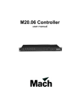
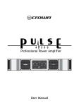
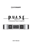
DPR 522
User Manual
1
V 1.0
JMK
11 June 1997
This equipment has been tested and found to comply with the following European and
international Standards for Electromagnetic Compatibility and Electrical Safety:
Radiated Emissions (EU):
RF Immunity (EU):
Mains Disturbance (EU):
Electrical Safety (EU):
Radiated Emissions (USA):
Electrical Safety (USA):
Electrical Safety (CAN):
EN55013
(1990) Associated Equipment
EN50082/1
(1992) RF Immunity, Fast Transients ESD
EN61000/3/2
(1995)
EN60065
(1993)
FCC part 15 Class B
UL813/ETL
(1996) Commercial Audio Equipment
UL813/ETLc
(1996) Commercial Audio Equipment
IMPORTANT SAFETY INFORMATION
DO NOT REMOVE COVERS. NO USER SERVICEABLE PARTS INSIDE, REFER SERVICING TO QUALIFIED
SERVICE PERSONNEL. THIS EQUIPMENT MUST BE EARTHED.
IT SHOULD NOT BE NECESSARY TO REMOVE ANY PROTECTIVE EARTH OR SIGNAL CABLE SHIELD
CONNECTIONS TO PREVENT GROUND LOOPS. ANY SUCH DISCONNECTIONS ARE OUTSIDE THE
RECOMMENDED PRACTISE OF BSS AUDIO AND WILL RENDER ANY EMC OR SAFETY CERTIFICATION
VOID.
For continued compliance with international EMC legislation ensure that all input and output cables are wired
with the cable screen connected to Pin 1 of the XLR connectors and/or the jack plug sleeve. The input XLR Pin
1 and the side-chain input jack socket sleeve are connected to the chassis via a low value capacitor, providing
high immunity from ground loops whilst ensuring good EMC performance.
Please read
We have written this manual with the aim of helping installers, sound engineers and musicians alike to get the
most out of the DPR-522. We recommend that you read this manual, particularly the section on installation,
before attempting to operate the unit.
The manual is split into two main sections. The first deals with quick reference information, regarding the
functions and operation of the unit, while the second covers a more general background to use and application
of the DPR-522.
We welcome any comments or questions regarding the DPR-522 or other BSS products, and you may contact
us at the address or World Wide Web site given in the warranty section.
2
Contents
Contents
1.0
Mechanical installation
5
2.0
Mains Power Connection
Mains Power
6
6
3.0
Introduction
7
4.0
Unpacking
7
5.0
5.1
5.2
5.3
5.4
Audio Connections
Main Inputs
Main Outputs
Key returns
Key send
10
10
10
11
12
6.1
6.2
6.3
6.4
6.5
6.6
6.7
6.8
6.9
6.10
6.11
6.12
6.13
6.14
6.15
6.16
6.17
6.18
6.19
Control Operations
Channel In
Key filter
Width
Key listen
Ext key
Threshold
Key level meter
Range
Attack
ADE
Hold
Release
Open check
Duck mode
Stereo link
Gate open indicator
Key send connector
Key return connector
Control connector
13
13
13
13
14
14
14
15
15
16
16
17
17
17
18
18
19
20
20
20
2.1
6.0
3
Contents
7.0
7.1
7.2
Beginners guide
What are gates for?
Basic operation
22
22
23
8.1
8.2
8.3
8.4
General applications
Basic gating
Frequency conscious gating
Ducking
Using the Key filter as EQ
24
24
24
25
25
Warranty Information
26
10.0
Specifications
27
11.0
Glossary
28
Index
30
User Notes
32
8.0
9.0
4
Mechanical Installation
1.0
Mechanical installation
A vertical rack space of 1U (1¾" / 44.5 mm high) is required, with a depth of
190mm. Ventilation gaps are unnecessary (See Figure 1.1).
If the unit is likely to undergo extreme vibration through extensive road
trucking and touring, it is advisable to support the unit at the rear and/or sides
to lessen the stress on the front mounting flange. The necessary support can
generally be bought ready-built as a rack tray, or the DPR-522 can be
mounted between other units. Damage caused by insufficient support is not
covered in the warranty. To prevent damage to the paintwork on the front
panel, always use protective plastic cups or washers underneath the rack
mounting bolts.
As with any low-level signal processing electronics, it is best to avoid
mounting the unit next to a strong source of magnetic radiation or heat, such
as a high power amplifier.
Fig 1.1 Unit dimensions.
Fig 1.2 Rack
dimensions.
5
Mains Power Connection
2.0
Mains Power Connection
2.1 Mains Power WARNING! THIS APPLIANCE MUST BE EARTHED.
The DPR-522 must always be connected to a 3-wire earthed AC outlet. The
rack framework must also be connected to the same grounding circuit. The
unit must NOT be operated unless the power cables' EARTH (ground) wire is
properly terminated - this is important for personal safety as well as for proper
control over the system grounding.
The wires in the mains lead are colour coded in accordance with the
following code.
Green and Yellow......Earth
Blue......Neutral
Brown......Live
Those units supplied to the North American market will have an integral
moulded 3 pin connector which is provided to satisfy required local standards.
IMPORTANT: The DPR-522 is designed to use 50/60Hz AC power in one of
the two voltage ranges, selectable with the mains voltage selector switch on
the rear of the unit. It is vital that the position of this switch is checked
BEFORE initial power up to ensure that it matches the local mains supply.
Acceptable input AC supply voltages range from:
115V switch position
230V switch position
-
90V to 132V
190V to 265V
The application of voltages outside these ranges may cause permanent
damage or erratic operation of the unit, and will invalidate the warranty.
IMPORTANT: The mains fuse carrier on the rear of the unit must be fitted with
the correct type and rating of fuse, depending on the position of the mains
voltage selector switch:
115V switch position
230V switch position
-
T315mA fuse
T200mA fuse
In the unlikely event of the mains fuse failing without good reason,
DISCONNECT THE UNIT FROM THE MAINS SUPPLY, and always replace
with the appropriately rated fuse (as specified above) for continued protection
against damage and fire.
Note: For USA and Canadian users, the replacement fuse must be of an
identical UL rated type fuse for continued compliance with safety standards.
6
Introduction
Unpacking
3.0
Introduction
The BSS DPR-522 is a dual channel high performance professional noise gate
which has been designed to be simple and intuitive to use. Many of the
facilities provided on the unique BSS DPR-502 unit, such as the parametric
key filters and key signal metering have been incorporated, with some new
features added.
One unique feature of BSS gates, featured in the DPR-522, is the adoption of
true logarithmic audio level control during both the attack AND release
phases. This ensures the most natural sounding fades, which are very
important if long attack or release times are used.
The provision of balanced key send and return signals minimises the
possibility of interference, which other units with unbalanced connections
may suffer from, whilst having separate send and return connectors eases the
integration of other equipment with the DPR-522.
To further enhance the unit's flexibility, extensive control of the DPR-522 is
possible using external DC control signals and switches; inputs are available
to remotely trigger the gate or inhibit it. Both contact closure and logic signals
may be used for this. In addition a signal is provided by the DPR-522 when the
gate opens, which may be used to trigger other external equipment.
4.0
Unpacking
As part of the BSS system of quality control, we check every product carefully
before packing to ensure that it reaches you in flawless condition.
Before you go any further, please check the unit for any physical damage and
retain the shipping carton and all relevant packing materials for use, should
the unit need returning.
In the event that damage has occurred, please notify your dealer
immediately, so that a written claim to cover the damages can be initiated.
Check out section 9.0; warranty section, for more info on the warranty, and
also to record your dealer details.
7
The DPR-522
Fig 4.1 Front Panel
Fig 4.2 Rear Panel
8
All numbers in bubbles refer to Section numbers.
9
Audio Connections
5.0
Audio Connections
5.1 Main Inputs
There are 2 input sockets on the rear panel of the 522, Inputs 1 and 2. Each is
electronically balanced on standard 3 pin female XLRs at an impedance
greater than 10k Ohms. The ‘HOT, + or in phase’ connection is to pin 2 and
the ‘COLD, -, or out of phase’ connection is to pin 3. Pin 1 is internally
connected to the chassis earth via a low value capacitor. This ensures
freedom from ground loops whilst allowing good EMC performance. The
screen of the input cable should be connected to pin 1 to ensure that EMC
regulations are being met, and the cable shield ground should also be
connected to the equipment which is providing the input signal.
Fig 5.1
522
When feeding the DPR-522 from unbalanced sources, connect the signal
conductor to pin 2 and the cable screen to pins 1 and 3. Transformer isolated
inputs are available as a dealer fitted option.
Fig 5.2
5.2 Main Outputs
522
The output signals are electronically balanced and fully floating on 3 pin
male XLRs. Full headroom is available into any load of 600 Ohms or greater.
The signal ‘HOT, +, or in phase’ signal is to pin 2, the ‘COLD, -, or out of
phase’ signal is to pin 3, with pin 1 being connected directly to the chassis.
Fig 5.3
522
10
When using the DPR-522 to drive unbalanced inputs, best performance is
usually obtained by connecting the DPR-522s ‘+’ signal to the equipment
signal pin and the ‘-’ signal to the equipment shield.
Fig 5.4
522
The DPR-522 shield should normally be connected to the equipment shield,
preferably at the equipment end. Transformer isolated outputs are also
available as a dealer fitted option.
5.3 Key returns
The side chain insert inputs are electronically balanced via stereo 5mm jack
sockets at an impedance greater than 100k Ohms. The ‘HOT, +, or in phase’
connection is to the jack plug tip, the ‘COLD, - or out of phase’ connection to
the ring. The shield is internally connected to the chassis earth via a low
value capacitor. This ensures freedom from ground loops whilst allowing good
EMC performance. The screen of the cable must be connected to the jack
plug shield to ensure continued compliance with EMC regulations. The cable
shield ground should be connected to the equipment which is providing the
input signal.
Fig 5.5
522 Jack Input
When feeding the DPR-522 from unbalanced sources, connect the signal
conductor to the jack plug tip and the cable screen to the plug ring and
shield.
Fig 5.6
522 Jack Input
11
Audio Connections
5.4 Key send
The side chain uses a quasi-balanced ‘ground compensated’ output. When
connected to a balanced input, interference rejection equivalent to a fully
floating output can be obtained. Full headroom is available into any load of
2k Ohms or greater. The signal ‘HOT, +, or in phase’ signal is to the jack plug
tip. The ‘COLD, -, or out of phase’ signal is to the ring with the shield being
connected directly to the chassis.
Fig 5.7
522 Jack Output
Connection to unbalanced inputs may be done by connecting the tip to the
signal input and the ring to the input shield. The DPR-522 shield may or may
not be connected to the equipment shield at the equipment end.
Fig 5.8
522 Jack Output
12
Control operations
6.0
Control Operations
6.1 Channel In
When the CHANNEL IN switch is in the out, non illuminated position, all
DPR-522 functions are bypassed and the input is connected directly to the
output with a high quality relay. This is the same condition that occurs when
the power is off, and ensures that signal is passed through the unit in the case
of a power or fuse failure. When the switch is pushed, the processed signal is
present on the output.
In bypass mode, the input is still connected to all of the DPR-522 circuitry, so
that all of the required facilities can be selected and set up prior to operating
the CHANNEL switch and going ‘on-air’.
6.2 Key filter
This control adjusts the centre frequency of the internal key parametric filter.
This filter is used to control the frequency content of the signal being sent to
the gate control circuitry to allow the filtering out of signals not required to
control the gating action. The filter is not placed in the main signal path, and
therefore has no effect whatsoever on the program material passing through
the gate.
6.3 Width
This control adjusts the width of the internal key filter. This filter should be
considered as a pair of tracking high pass and low pass filters, with the space
between them controlled by the WIDTH control. It is thus possible to achieve
a variety of key filter responses, from a very broad filter encompassing the
entire audio band to a very narrow one for a very selective response.
Normally it is best to start off with a fairly wide setting and then narrow down
on the signal of interest, readjusting the KEY FILTER control if required.
13
Control operations
This type of filter not only allows band-pass configurations, but also, by the
appropriate setting of the KEY FILTER and WIDTH controls, the conventional
low pass or high pass configurations can be easily realised. Experience will
show that this approach gives considerable operational advantages for the user
over the more simple separate low/high pass filter approach.
6.4 Key listen
When this switch is depressed, it connects the output of the key filter to the
output connector instead of the normal signal. This makes it very easy to
adjust the KEY FILTER and WIDTH controls to ‘home in’ on the signal that is
required to open the gate. To enable both hands to be used for adjusting the
key filter, this switch is latching, and may therefore be left engaged by
accident rendering the gate function inoperable - the switch illuminates red to
warn you of this.
6.5 Ext key
Normally with this switch out (un-illuminated), the input to the key filter is
taken from the main input, allowing the main signal to gate itself. If it is
desired to use other audio signals as a trigger, these may be applied to the
rear panel KEY RETURN socket with the EXT KEY switch depressed. This
signal can be heard by depressing KEY LISTEN, and both the filter controls and
gate control will now work on this signal.
6.6 Threshold
The filtered key signal is passed to the THRESHOLD control. The numbers
around the THRESHOLD control indicate the approximate level in dBu that
will be required from the key filter in order to just cause the gate to open.
14
With the control fully clockwise in the ‘out’ position, the gate will be held
closed at all times. As the control is rotated anticlockwise, the threshold point
is progressively reduced, or becomes more sensitive. You will find that as you
set the WIDTH control narrower, it is generally required to reduce the
threshold level to compensate for the smaller amount of energy being passed
from the filter.
In normal use the threshold control is generally set so that wanted signal
peaks are just able to trigger the gate, this gives the maximum protection from
false triggering by undesired signals.
6.7 Key level meter
The relationship between the actual trigger signal (as set by the threshold
control) to the gate trigger point is displayed on the KEY LEVEL METER. This
meter displays the level of the key signal in dB relative to the level required
to ‘open’ the gate. This level is the larger segment marked ‘TH’ on the meter.
Notice that even with no key signal present the TH segment glows dimly, to
ensure that even in dark conditions, the trigger point is visible. The meter has
a very fast response time coupled with a decay time optimised to allow you to
see rapidly recurring signal peaks.
6.8 Range
With the gate ‘open’, the program can pass through the DPR-522 unhindered.
When ‘shut’, the level of the program passed is set with the RANGE control.
This can be varied from the full input level in the ‘out’ position to more than
80dB reduction - effectively no signal at all.
Intermediate settings of the range control are often used to avoid the signal
sounding ‘dead’ when the gate is shut, or to enhance or make less audible the
gate dynamics. This is done by limiting the open to closed gain ratio to the
minimum required.
Remember also that if a very fast attack time is desired, it will take the DPR522 longer to open from -80dB than from, for example, -20dB.
15
Control operations
6.9 Attack
Once the key level exceeds the threshold, the gate will start to open. The
time it takes to open is set with the ATTACK control. For conventional gating,
fast attack settings are usually desired to ensure that the minimum wanted
program is lost. However, unnecessarily fast attack times should be avoided
as they can produce a ‘click’. This click is not generated by the DPR-522 but
is an artifact produced by the action of quickly switching a signal. To prevent
this, increase the attack time until a compromise is found.
Very slow attack times are available for special effects or when triggering the
DPR-522 from either an external key or a DC or switch control to produce
smooth fades. Because the DPR-522 uses true logarithmic level control during
the attack phase, these fades will sound very natural.
The attack phase, once initiated, will continue until the gate is fully open,
even if the signal momentarily falls below the threshold level. This is
important as it allows for both a clean, 'chatter free' attack phase and ensures
that, especially with short hold and release times, the gate does not try to
follow individual cycles of the program.
6.10 ADE
Auto Dynamic Envelope is a technique developed by BSS to help restore an
effective leading edge transient to the front of a gated program signal. As
stated above, it is often necessary to use a longer than ideal attack time, this
can result in the loss of part of the original signals’ initial transient.
ADE operates at the commencement of each attack timing period, and allows
the gate to ‘overshoot’, or provide gain, in a controlled way. This is most
effective on single bursts of repetitive program that are percussive in nature
and is used to restore ‘punch’ into the program sound.
In operation, and depending on the nature of the program, ADE can provide a
substantial subjective improvement to the sound and help to eliminate the
dead or gated signature that is often imparted to signals.
16
6.11 Hold
After the attack time is completed, the DPR-522 keeps the gate fully open for
a time determined by the HOLD control. Hold is required to avoid the DPR522 from starting another attack sequence if the key signal momentarily falls
below the threshold level.
The hold time is reset every time an above threshold event is detected and
therefore if there is never a pause in the program longer than the hold time,
the gate will never shut.
Short hold times can be used to help minimise jitter (the gate repeatedly
opening and shutting very quickly). Longer times would be used when gating
for example a vocal, to avoid the gate closing between words.
6.12 Release
This is the final phase of operation and is entered after the HOLD time has
expired. At the end of the time set with the RELEASE control, the signal will
be reduced by the amount set on the RANGE control. During release the
signal is reduced logarithmically. This produces a very natural sounding fade,
essential for long release times.
6.13 Open check
Depressing this switch will force the DPR-522 to commence its attach phase.
It will stay open until the switch is released. Once released the DPR-522 will
commence its hold and release phases.
Open check is especially useful for listening to the input signal if the DPR-522
is setup to be triggered by a signal other than the program. It can also be used
during live performances as a means of forcing open gated microphone lines
to test their integrity.
17
Control operations
6.14 Duck mode
Normally the DPR-522 would be configured as a gate, that is to say that the
signal will be ‘cut off’ unless triggered, whereupon the signal will be passed
through. DUCK MODE forces the opposite to happen; i.e. when there is NO
trigger event (signal above threshold or DC/switch trigger) the DPR-522 will
pass signals. When triggered by any of the normal means, the DPR-522 will
attenuate the program to a level set by the range control.
This facility is most often used in broadcast or PA applications to allow an
announcer to ‘talk over’ the normal program.
In duck mode the operation of the attack and release controls could be
considered reversed. The time taken for the DPR-522 to reduce the program
after being triggered is set with the RELEASE control, the time to restore the
program after the event is set with the ATTACK control. The HOLD control
works in the normal way.
6.15 Stereo link
With this switch depressed, both channels of the DPR-522 can be made to
operate simultaneously.
The key signals from both channels are added together and applied to the
controls and key level meter of channel 1 for processing in the normal
manner. The gain control stage for channel 2 is disconnected from the
channel 2 controls and connected instead to the control from channel 1.
Therefore if either channel provides a sufficiently large key signal, both
channels will open together with the gate status being displayed on channel
1s LEDs.
In STEREO LINK mode, all the controls on channel 2, including the meter and
status LEDs EXCEPT KEY EXT, are disabled. Channel 2 KEY EXT still operates
and will select either the channel 2 main signal or the channel 2 key return
signal for summing to channel 1.
If it is not required for the side-chain signal of channel 2 to be summed with
channel one, or visa versa, then the respective KEY EXT switch should be
depressed. This then disconnects that channel’s signal - provided nothing is
externally connected to the rear panel KEY IN jack socket.
The main program inputs and outputs are not connected in any way in stereo
mode, only the gating functions are linked together.
18
6.16 Gate open
indicator
If the gate is not passing program, the SHUT LED is illuminated. If it is passing
program, the OPEN LED is illuminated.
These LEDs fade from one to another during the attack and release times, their
relative intensity gives a visual indication of the dynamic response of the
gating action.
One thing to remember is that during the attack and release phases, as stated
earlier, the DPR-522 uses a logarithmic control law to give a smooth fade to
the sound. When this is applied to the LEDs, especially for long release times,
it may appear as though nothing happens for a while. What is in reality
happening is that the sound and LEDs are fading but the LEDs are initially
fading too slowly to be obvious.
19
Control operations
6.17 Key send
connector
This is a ‘pseudo balanced’ output and carries a buffered version of the signal
applied to the MAIN input. It may be used as such, or can be connected to
the input of external equipment for further processing. Refer to section 5.1 for
the wiring details of this connector.
6.18 Key return
connector
If the KEY EXT switch is depressed, this fully balanced socket is the input to
the DPR-522’s key side chain. It may be used as the return input from
equipment being driven from the DPR-522’s KEY SEND connector, of if
desired may be driven from another unrelated signal. Refer to section 5.4 for
the wiring details of this connector.
6.19 Control
connector
This is an 8 pin DIN socket that provides a means for externally controlling
the DPR-522 using switched or logic signals. The pins are assigned as follows:
1 GATE OPEN open collector output
2 GROUND
3 DISABLE HIGH input
4 PULLUP to +15V
5 EXTERNAL TRIGGER input
6 DISABLE LOW input
7 DISABLE PULLUP to +15V
8 GROUND
20
Pin 1 GATE OPEN Output
An open collector output that goes LOW when the DPR-522 is passing signals.
If an external pullup is used, limit the current passed by this pin to below
50mA at a voltage no higher than 25V. If desired this pin can be connected to
an internal pullup on pin 4 to provide a signal that swings positive to +15V
when the DPR-522 is not passing signals.
Pin 5 EXTERNAL TRIGGER Input (High to trigger)
Taking this pin to within 0.5V of ground with either a switch or logic level
will cause the DPR-522 to open. This pin should never be made higher than
25V. If it is desired to use a normally open switch to trigger the DPR-522,
connect this switch between this pin and ground. The DPR-522 will still
respond to internal triggers. If this is not required, rotate the THRESHOLD
control fully clockwise to the OUT position.
Pin 6 DISABLE LOW Input
If it is desired to use a normally open switch to DISABLE the DPR-522,
connect this switch between this pin and ground. Please note that this input
cannot be used when the DISABLE HIGH input is in use.
Pin 3 DISABLE HIGH Input (Switch closed to inhibit)
A voltage between 1V and 25V on this pin will stop the DPR-522 from
opening. If it is desired to use a normally open switch to ENABLE the DPR522, connect this pin to pin 7, and the switch between pin 3 and ground.
Please note that this input cannot be used when the DISABLE LOW input is in
use.
21
Beginners guide
7.0
Beginners guide
7.1 What are gates
for?
Put simply, a noise gate is a device that blocks or switches off a signal if that
signal falls below a certain preset level. Originally noise gates were used for
just that, gating or removing noise from recordings. For example traffic rumble
in studios, or electronic noise from old tape loop echo chambers.
Noise gates or gates function by taking the main input signal and splitting it
into two paths. One path passes through an electronic switch to the output and
is not modified in any other way. The other, called the KEY SIGNAL is
processed to provide a ‘trigger’ for the switch. Once the main signal has
exceeded the user selected THRESHOLD and provided the trigger, the gate
will open. In modern gates the switch is replaced by a fader circuit, thereby
allowing the gated signal to be faded up and down, often quite slowly. The
fade up rate is defined by an ATTACK control, the fade down by a RELEASE
control. This fading action can be important, as the ear is much more sensitive
to abrupt changes in level than gradual ones.
One major application for modern advanced gates is the separation of sounds
so that they may be processed separately, for example in a multi-miked drum
kit. In this case each drum would have a separate microphone, the intention
being to have independent control of the level and tonal balance of each
drum. Unfortunately, due to the close proximity of the microphones, there will
be significant bleed of sound from one drum to another. Gates are used to
prevent this. They are set up to only open when their particular drum is hit.
Unfortunate it is sometimes not easy to set a gate up to only trigger on the
desired signal, quite often the wanted and unwanted signals are close to each
other in level. This is where key filters are useful. Key filters are setup to
condition the key signal by filtering out signals that don't originate from the
drum in question, thereby increasing the difference between adjacent drums
and making the job of ensuring that only the correct drum triggers the gate
easier.
Another use for gates is in the reshaping of existing sounds. Quite often
sampled sounds will be used in recording. Sometimes these sounds may have
an inappropriate attack or release sound for their intended purpose. By
triggering a gate on the sample, and with careful setting of the attack and
release controls, a new envelope, that produced by the gate, will be imparted
to the sampled sound.
Additional features are often added to contemporary gates, for example, the
ability to trigger the gate with a signal that is not the same as the one being
gated, or using external switches or logic signals to open or inhibit the gate.
By introducing the possibility of control via a computer or sequencer, these
facilities add enormously to the versatility of the unit and take its application
into areas far removed from the original intention of the designers of the first
‘noise gates’.
7.2 Basic operation
22
These instructions are primarily designed to help you get started using the
DPR-522.
The front panel is split down the middle into two identical sections or
channels. The left hand section will be referred to as channel 1, and the right
hand section as channel 2. There is no difference in operation between these
two channels, and so all the discussions will equally apply to both. The
exception to this is STEREO LINK mode (described in section 6.15).
In operation, the DPR-522 can be considered as an automatic on-off switch
that is placed into the program signal line, the actual operation of the switch
being controlled by the loudness level of the signal. The simplest way to
understand the basic operation is to connect one gate channel into a program
source and operate the controls whilst listening to their effect.
Having connected the input and output leads according to the instructions in
section 5 continue as follows:
1 Make sure that all push-buttons are out, in the non-illuminated position.
2 Set the ‘KEY FILTER’ control to 1KHz, and the WIDTH control to 8 oct.
3 Set THRESHOLD control to out, the RANGE control to 80dB, and the
ATTACK, HOLD, RELEASE controls about centrally on their scale.
4 With the unit still in bypass mode (Channel button out) adjust the external
equipment to give an adequate volume level, and then operate the CHANNEL
switch. The signal should then be cut-off, and there will be no meter display.
5 Now gradually rotate the THRESHOLD control anticlockwise, and observe
that the KEY LEVEL meter starts to indicate the peaks of the program. As soon
as the display exceeds the partially illuminated TH marker on the meter, the
program signal will be passed through to the output as the gate has now
‘opened’ notice too that the green OPEN LED has come on. Spend a few
minutes adjusting the threshold control and watching the display.
6 Now adjust the RANGE control whilst listening to the program. The scale
calibration indicates the attenuation of the signal when the gate is closed.
This means that, rather than being simply on or off, the gate can be set to be
slightly attenuated, or somewhere in between. Turning the control fully
clockwise makes the gate closed level equal to the gate open level, and so it
will appear that the gate is open at all times. The normal setting for this
control will depend very much on the specific application, however for
general noise reduction on background microphone clutter, a range of 20-40
dB will be a good starting point.
7 The ATTACK, HOLD and RELEASE controls can be intuitively operated. The
ATTACK is the time taken for the gate to open once the threshold has been
reached. The HOLD is the time the gate will remain fully open once the
program signal has fallen below threshold. The RELEASE is the time taken for
the gate to fully close once the hold cycle has finished. Take some time to
experiment with these controls to hear their effects on the envelope of the
program signal. Whilst doing this also observe how the gate OPEN and SHUT
LEDs fade between each other, precisely following the sound. You will notice
that these follow the actual times set by the ATTACK, HOLD and RELEASE
controls and is a true indication dynamically of the state of the gate, whereas
the KEY LEVEL meter has dynamics set to give a good indication of program
level.
This covers the basic operation of the DPR-522. For a more detailed
description of the controls, please refer to sections 6.1 thru 6.19. For
information covering specific configurations, please see section 8.0.
23
General applications
8.0
General applications
8.1 Basic gating
Rotate the THRESHOLD control to the OUT position, apply a signal to the
MAIN input and observe that there is no output. Rotating the THRESHOLD
control anticlockwise, you should see some indication on the KEY LEVEL
meter. When this activity exceeds the TH mark on the meter you will hear the
signal appear and should see the GATE LEDs change state. If the signal is only
allowed to briefly exceed the TH level the sound will appear chopped up.
Adjusting the ATTACK, HOLD and RELEASE controls will change the nature
of the sound. You may find that certain settings of these controls never allow
the gate to close.
Set the THRESHOLD so that the gate no longer opens, and now adjust the
RANGE control. Notice that even though the gate is shut, as confirmed by the
GATE LEDs, you can adjust the sound level anywhere between fully off and
fully on. This can be useful as having the gate close too far can impart an
unnatural character to the sound.
8.2 Frequency
conscious gating
Set the KEY filter control to 1KHz and the WIDTH control to 8 oct. With a
signal applied to the MAIN input and depressing the EXT KEY switch, you
should now hear the program. Rotate the WIDTH control and notice that the
range of the sound changes, becoming more limited as the control is rotated
anticlockwise.
Leave the WIDTH control in approximately the 9 o’clock position and now
adjust the KEY FILTER control. As you turn it anticlockwise, the bass notes
will become prominent. Turning the control clockwise will cause the treble to
become more prominent.
Select some music with a heavy beat and set the KEY FILTER and WIDTH
controls so that the beat notes are the ones registering on the KEY LEVEL
meter. When you are happy with the filter controls, release the KEY LISTEN
switch. Now adjust the THRESHOLD control until the beats, as displayed on
the meter, just exceed the TH mark, you should now hear the beats in the
program. Experiment with the filter and the ATTACK, HOLD & release
controls to extract other sounds in the program.
24
8.3 Ducking
For this example, a DJ ‘talkover’ application will be described. Apply the
program that you wish to ‘duck’ to the MAIN input. Apply the DJ program that
you want to cause the ducking action to the KEY RETURN input. Remember
that if you wish to use a microphone as this signal, it may need amplifying
first.
Adjust the THRESHOLD control until the KEY LEVEL meter is swinging above
the TH point when the DJ speaks. Adjust the RANGE control to give the
required degree of ducking. Now set the RELEASE control so that when the DJ
speaks, the program is attenuated smoothly. Set the HOLD so that the DPR522 does not change state between words, and adjust the ATTACK control so
that when there is no DJ input the main program fades up appropriately.
8.4 Using the Key
filter as EQ
This is an unusual application as it does not use the DPR-522 as a gate. Each
channel of the DPR-522 contains a good quality wide ranging parametric
filter. This filter can be accessed by depressing the KEY LISTEN button, which
passes the output of the key filter to the output. If the EXT KEY switch is out,
the signal filtered will be that applied to the MAIN input. If the DPR-522 is
used in this way, none of the gating features for that channel will be available
and no controls other than those for the filter will be operable.
Note: Controls shown in dark grey should be initially be set to the positions in
the diagram, and the text will guide you through the application procedure.
Light grey controls with no markers can be set at any position, and do not
affect the setup of a particular application.
25
Warranty Info
9.0
Warranty Information
When sold to an end user by BSS Audio or a BSS Audio Authorised Reseller,
this unit is warranted by the seller to the purchaser against defects in
workmanship and the materials used in its manufacture for a period of one
year from the date of sale.
Faults arising from misuse, unauthorised modifications or accidents are not
covered under this warranty. No other warranty is expressed or implied.
If the unit is faulty it should be sent to the seller of the equipment, in its
original packaging with shipping prepaid. The unit will be returned to you
when the repair has been completed. If the unit was purchased in the
European Union, you may, as an alternative, return the unit to any other BSS
distributor in the European Union.
You should include a statement listing the faults found. The unit’s serial
number must be quoted in all correspondence relating to a claim.
IMPORTANT
We recommend that you record your purchase information here for future
reference.
Dealer Name:
Dealer Address:
Post/Zip Code:
Dealer Phone No.:
Dealer Contact Name:
Invoice/Receipt No.:
Date of Purchase:
Unit Serial Number:
In keeping with our policy of continued improvement, BSS Audio reserves the
right to alter specifications without prior notice.
The DPR-522 was designed and developed by BSS Audio, Hertfordshire,
England.
Phone (+44) (0)1707 660667. Fax (+44) (0)1707 660755.
World Wide Web address: http://www.bss.co.uk
26
Specifications
10.0
Specifications
General
Input Impedance
Input Headroom
Input CMRR
Max Output level
Output Impedance
Frequency Response
Noise
Dynamic Range
Cross Talk
Distortion
10k ohm balanced or unbalanced
>+20dBu
>-50dB (30Hz-20kHz)
>+20dBu into 600 ohms or greater
<50 Ohms unbalanced or unbalanced
10Hz-80kHz (+/-3dB)
-96dBu (22Hz to 22kHz)
>117dB
>-85dB (20Hz to 20kHz)
<0.005%THD (80kHz measurement BW) 20Hz-20kHz. Typically 0.002% at
1kHz, Unity Gain +10dBm output below threshold
Gate
Threshold range
Attenuation range
Attack time
Hold time
Release time
Noise
-50dB to +20dB continuously variable
-80dB to 0dB
µs to 1.5s continuously variable
20µ
5ms to 2s continuously variable
1ms to 5s continuously variable
<-94dBu (Open)
<-98dBu (Closed)
27
Glossary
11.0
Glossary
Active
ADE
Active electronic circuits are those which are capable of voltage and power
gain by using transistors and integrated circuits.
A special BSS feature that can be used to impart a new leading edge transient
on sounds to make them sound less 'gated' and more punchy.
Amplitude
Refers to the voltage level or intensity of a signal, and is usually measured in
voltage or decibels.
Attack Time
The amount of time taken for the compressor or limiter to kick in and start
gain reduction once the input signal has exceeded the threshold level. This is
usually measured in micro or milliseconds (millionths or thousandths of a
second).
Balanced
dB
A three wire connection in which two of the wires carry the signal
information, and the third acts as a shield tied to chassis ground. The two
signal lines are of opposite polarity (out of phase by 180 degrees) at any given
moment in time, and are of equal potential with respect to ground. Balanced
connections are used to reduce hum and noise in system interconnections.
A unit for expressing the ratio between two signal levels for comparison
purposes. On its own it has no absolute level meaning. Rather, it is a
logarithmic ratio used to express the differences between two amounts or
levels. Positive numbers indicate an increase, and negative ones a decrease.
Some useful ratios are:
+3dB
+6dB
+10dB
+20dB
dBm
dBu or dBv
dBV
Distortion
28
=
=
=
=
Double Power
x 2 Voltage or x 4 Power
x 3 Voltage or x 10 Power
x 10 Voltage or x 100 Power
The addition of ‘m’ after dB indicates an absolute scaling for the dB ratio.
Instead of a ratio, the dB becomes a measure of voltage. 0dBm = a power
level of 1 milliwatt into a load of 600 ohms. It is also loosely used to describe
signal voltage in 600 ohm circuits.
The addition of ‘u’ or ‘v’ after dB indicates an absolute scaling for the dB
ratio. 0dBu (or 0 dBv) = 778mV or 0.778 Volts, and it has no regard for power
or impedance. This term is widely used for expressing signal voltages in
modern audio equipment with high input impedances and low output
impedances.
The same scale as for dBu as above, except that 0dBV = 1.0 Volts.
Any modification of a signal which produces new frequency components not
presents in the original. Harmonic distortion refers to added frequencies
that are overtones to the fundamental frequency. Intermodulation distortion
refers to added frequencies that are sum and difference values derived from
the beating together of two frequencies.
Drop-in
Duck
Equalisation
Frequency
Frequency Response
Headroom
Hold
Impedance
Key
Level
Line Level
Octave
Release Time
A term used to describe the way in which new equipment, or a hitherto
unused function of equipment already connected, can be switched into a live
sound system without causing unwanted effects, i.e: without causing clicks or
a noticable change in sound level.
The term given to a unit that attenuates the program when another signal
exceeds a threshold level. This is approximately the opposite of what a gate
does.
Modification of the frequency response of an audio system, regardless of
level, for corrective or enhancement purposes.
The repetition of a waveform. The unit of frequency is Hz, and 1 cycle per
second is equal to 1Hz. The audio band is generally restricted to frequencies
of 20Hz to 20,000Hz (20kHz).
The equipment’s relative gain compared to frequency. Generally expressed
as +/- a certain number of dBs from 20Hz to 20kHz.
The amount, in dBs, above the normal operating level that can be used before
serious distortion commences.
The time that the gate pauses after the ATTACK phase, before commencing
the RELEASE phase.
The AC equivalent of resistance and measured in ohms. It indicates the
amount of drive required for an input, or the drive capability of an output, at a
given signal level.
The signal that is processed to produce the gate trigger. This may or may not
be the same as the main program.
The amplitude of a signal, measured in Volts or Decibels.
Generally indicates a signal whose level is between -10 and +10dBu or -14
to +6 dBV. Mic level refers to levels around -40dBu.
A logarithmic unit for expressing frequency ratios. Positive values indicate an
increase and negative ones a decrease. One octave ‘up’ the scale is
equivalent to double the frequency. One octave ‘down’ is equivalent to half
the frequency.
The time required for a compressor or limiter to restore its gain to normal, after
the input signal has fallen below threshold.
Threshold
The pre-settable level above which a compressor or limiter will commence to
gain reduce.
Transient
A sudden burst of energy in an audio signal which only lasts for a small period
of time relative to the rest of the signal. The level of these transients can often
reach 10 times (+20dB) or so above the normal operating level of the audio
equipment, and may cause distortion of headroom is inadequate.
Side chain
The part of the circuit responsible for producing the gate trigger signal. See
also 'Key'.
29
Index
Index
A
ADE
Applications
Basic gating
Ducking
Frequency conscious gating
Using the Key filter as EQ
Attack
Audio connections
Inputs
10, 13,
Key return
Key send
Outputs
E
16
24
25
24
25
16
22
11
12
10
24
22
22
C
Channel In
Connector
control
Key return
Key send
Controls
ADE
Attack
Channel In
Duck
Ext key
Gate open
Hold
Key filter
Key listen
Open check
Range
Release
Stereo link
Threshold
Width
20
20
20
16
16
13
18
14
19
17
13
14
17
15
17
18
14
13
D
Dimensions
Duck mode
Ducking
30
Frequency conscious gating
Front Panel
Fuse rating
5
18
25
25
14
24
8
6
G
19
28
H
Hold
17
I
Installation
13
6
F
Gate open
Glossary
B
Basic
gating
operation
Beginners guide
Earthing
EQ
using the Key filter as
Ext key
5
K
Key
filter
level meter
listen
return connector
send connector
13
15
14
20
20
M
Mechanical installation
Meter
Key level
5
15
O
Open check
17
P
Power
connection
requirements
6
6
R
Rack space
Range
Rear Panel
Release
5
15
8
17
S
Specifications
Stereo link
27
18
T
Threshold
14
U
Unpacking
7
V
Voltage selection
6
W
Warranty
Width
26
13
31
User Notes
32
33
User Notes
34
35
User Notes
36