1
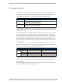
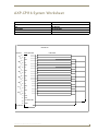
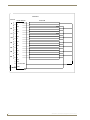
Operation/Reference Guide
AXP-CPI16
16-Channel Custom Panel Interface
Cu st o m P a n e l I n t er f a c e s
L as t R e vi s ed: 1 /1 3 /20 0 9
AMX Limited Warranty and Disclaimer
AMX warrants its products to be free of defects in material and workmanship under normal use for three (3) years from
the date of purchase from AMX, with the following exceptions:
•
Electroluminescent and LCD Control Panels are warranted for three (3) years, except for the display and touch
overlay components that are warranted for a period of one (1) year.
•
Disk drive mechanisms, pan/tilt heads, power supplies, and MX Series products are warranted for a period of one
(1) year.
•
AMX Lighting products are guaranteed to switch on and off any load that is properly connected to our lighting
products, as long as the AMX Lighting products are under warranty. AMX does guarantee the control of dimmable
loads that are properly connected to our lighting products. The dimming performance or quality cannot be
guaranteed due to the random combinations of dimmers, lamps and ballasts or transformers.
•
Unless otherwise specified, OEM and custom products are warranted for a period of one (1) year.
•
AMX Software is warranted for a period of ninety (90) days.
•
Batteries and incandescent lamps are not covered under the warranty.
This warranty extends only to products purchased directly from AMX or an Authorized AMX Dealer.
All products returned to AMX require a Return Material Authorization (RMA) number. The RMA number is obtained
from the AMX RMA Department. The RMA number must be clearly marked on the outside of each box. The RMA is
valid for a 30-day period. After the 30-day period the RMA will be cancelled. Any shipments received not consistent
with the RMA, or after the RMA is cancelled, will be refused. AMX is not responsible for products returned without a
valid RMA number.
AMX is not liable for any damages caused by its products or for the failure of its products to perform. This includes any
lost profits, lost savings, incidental damages, or consequential damages. AMX is not liable for any claim made by a
third party or by an AMX Dealer for a third party.
This limitation of liability applies whether damages are sought, or a claim is made, under this warranty or as a tort claim
(including negligence and strict product liability), a contract claim, or any other claim. This limitation of liability cannot
be waived or amended by any person. This limitation of liability will be effective even if AMX or an authorized
representative of AMX has been advised of the possibility of any such damages. This limitation of liability, however, will
not apply to claims for personal injury.
Some states do not allow a limitation of how long an implied warranty last. Some states do not allow the limitation or
exclusion of incidental or consequential damages for consumer products. In such states, the limitation or exclusion of
the Limited Warranty may not apply. This Limited Warranty gives the owner specific legal rights. The owner may also
have other rights that vary from state to state. The owner is advised to consult applicable state laws for full
determination of rights.
EXCEPT AS EXPRESSLY SET FORTH IN THIS WARRANTY, AMX MAKES NO OTHER WARRANTIES,
EXPRESSED OR IMPLIED, INCLUDING ANY IMPLIED WARRANTIES OF MERCHANTABILITY OR FITNESS FOR
A PARTICULAR PURPOSE. AMX EXPRESSLY DISCLAIMS ALL WARRANTIES NOT STATED IN THIS LIMITED
WARRANTY. ANY IMPLIED WARRANTIES THAT MAY BE IMPOSED BY LAW ARE LIMITED TO THE TERMS OF
THIS LIMITED WARRANTY.
Table of Contents
Table of Contents
Product Information ...........................................................................................1
Specifications............................................................................................................ 1
Installation ..........................................................................................................3
Mounting Dimensions ............................................................................................... 3
Setting the AXlink Device Number ........................................................................... 4
Preparing/connecting captive wires ................................................................................ 4
Connecting the Two 20-pin Headers ........................................................................ 4
Switch Wiring Diagrams............................................................................................ 5
Connecting the AXlink Wiring................................................................................... 5
Programming ......................................................................................................7
Testing the Unit ........................................................................................................ 8
AXP-CPI16 System Worksheet ...........................................................................9
AXP-CPI16 16-Channel Custom Panel Interface
i
Product Information
Product Information
The AMX AXP-CPI16 16 Channel Custom Panel Interface Board (FIG. 1) simplifies the process of
creating custom control panels for Axcess systems. Providing contact closure inputs and feedback
outputs for up to 16 buttons, the miniature PC board contains a 20-pin header for ribbon cable
installation or for direct mounting to a printed circuit board.
AXlink
Connector
Pin 1
20-Pin Header P3
Connect this side to the ribbon cable
Pin 1
Device
DIP Switch
AXlink Status LED
-Pin Header P2
onnect this side to the ribbon cable
Connect this side to
the PC board
FIG. 1 AXP-CPI16 components
Specifications
The following table lists product specifications for the AXP-CPI16.
AXP-CPI16 Specifications
Dimensions (HWD)
Power
2.75" x 1.75" x 0.062" (69.90 mm x 44.50 mm x 1.557 mm)
• Input voltage: 12 VDC (nominal)
• Current draw: 25mA
Inputs
16 closure inputs with a common ground (GND)
Outputs
16 open-collector outputs, acting as switch to ground, up to 100 mA DC each for:
• Board is not to supply more than 750 mA of +12V total.
• Small incandescent lamps
• LED indicators - with series resistor (1K for 12 VDC)
• Relays - with DC coil
AXlink Connector
A 4-pin (male) connector attached to a four-wire cable which sends control data from the
Axcess CardFrame to the AXP-CPI16.
Headers
Two 20-pin headers included for ribbon cables (up to 100 feet each) or for mounting
directly to a PC board.
AXP-CPI16 16-Channel Custom Panel Interface
1
AXP-CPI16 Specifications (Cont.)
AXlink Status LED
Indicates AXlink communication status as follows:
• One blink per second communication is functioning.
• Two blinks per second devices specified in the master program do not match the
specified devices found.
• Three blinks per second indicate an AXlink communication error.
• Full-on indicates there is no AXlink control or activity (but power is on), or the Axcess
program is not loaded.
2
Device DIP Switch
8-position DIP switch sets AXlink device ID.
Cables
Two 3-foot (91.4 cm) ribbon cables each with a female 20-pin header.
AXP-CPI16 16-Channel Custom Panel Interface
Installation
Mounting Dimensions
LH
B
B
AA
A
A
C
C
AXlink
AXlink
GND
PWRAXP
AXP AXM
GND
L
J
P1
1
1 22
P1
PWR AXM
P3
P3
Top View
(Component Side)
Top View
(Component Side)
DD
E
E
P2
P2
2
11
19
19 20
20
MM
20
20
19
19
J
G
F
F
KG
H
K
min
min
FIG. 1 AXP-CPI16 mounting dimensions
Mounting Dimensions
Item Inch
mm
Item Description
A
0.10
2.50
K
B
1.75
44.50 L
0.125 Inch (3.2 mm) mounting holes for #4-40 (3 mm) screws
C
1.55
39.40 M
P3 20-Pin Header .025 inch (6 mm) square pins, .1 inch (2.4 mm) typical
spacing
D
2.75
69.90
E
2.55
64.80
F
0.35
8.90
G
0.23
5.80
H
0.438 11.10
J
0.93
P2 20-Pin Header .025 inch (6 mm) square pins, .1 inch (2.4 mm) typical
spacing
23.6
AXP-CPI16 16-Channel Custom Panel Interface
3
Setting the AXlink Device Number
The 8-position device DIP switch defines the AXP-CPI16 as an AXlink device. It can be one of 255
devices in the Axcess Control System. Set the device number with the total value of all ON (down)
positions. As an example, the device DIP switch shown below defines device number 129 (1+128=129).
Position 1 2 3 4 5
Value
6
7
8
OFF
OFF
1 2 4 8 16 32 64 128
ON
ON
1
2 3 4 5
6 7 8
AMX standard device numbers are assigned as follows:
Cards are 1 through 25.
Boxes are 96 through 127.
Panels are 128 through 255.
1. Strip 0.25 inch of wire insulation off all wires.
2. Insert each wire into the appropriate opening on the connector according to the wiring diagrams and
connector types described in this section.
3. Tighten the screws to secure the wires. Do not tighten the screws excessively; doing so may strip the
threads and damage the connector.
Connecting the Two 20-pin Headers
The following chart notes the pinouts of the two 20-pin headers for P2 and P3.
AXP-CPI16 P2/P3 Pinouts
P2
P3
Pin Function Pin Function Pin Function Pin Function
1
Output 1
11
GND
1
Output 9
11
GND
2
Output 2
12
GND
2
Output 10
12
GND
3
Output 3
13
Input 1
3
Output 11
13
Input 9
4
Output 4
14
Input 2
4
Output 12
14
Input 10
5
Output 5
15
Input 3
5
Output 13
15
Input 11
6
Output 6
16
Input 4
6
Output 14
16
Input 12
7
Output 7
17
Input 5
7
Output 15
17
Input 13
8
Output 8
18
Input 6
8
Output 16
18
Input 14
9
GND
19
Input 7
9
GND
19
Input 15
10
PWR
20
Input 8
10
PWR
20
Input 16
Pin 10 provides +12 VDC power from AXlink bus. Add 1K series resistors when using AXP-CPI16 with
LED indicators receiving 12 VDC power from Pin 10.
4
AXP-CPI16 16-Channel Custom Panel Interface
Switch Wiring Diagrams
FIG. 2 diagrams LED and Switch wiring.
LED Wiring (Typical)
10
LED 1
1K
LED 2
1K
LED 3
1K
Switch Wiring (Typical)
SW 1
1
2
12
3
SW 2
SW 3
13
14
15
FIG. 2 LED and switch wiring diagrams
Connecting the AXlink Wiring
To install the AXlink data/power bus wiring.
1. Strip 0.25 inch off the wire insulation for all four wires. If the wire is 20 AWG or less, fold the
exposed wire over to obtain a positive connection.
2. Insert each wire into the appropriate opening on the connector, as shown in FIG. 3.
AXlink
PWR
PWR
AXP
AXP
AXM
AXM
GND
GND
Device
FIG. 3 AXlink wiring diagram
3. Tighten the screws to secure the fit.
AXP-CPI16 16-Channel Custom Panel Interface
5
Programming
Programming
Use the same Axcess commands as with other AXlink control panels, such as the AXU-MSP series
mini-softwire panels. When using the AXP-CPI16 as a control device, use On, Off, and Pulse commands
to control sources connected to outputs and Push and Release commands to receive inputs. For
additional information, refer to the Axcess Programming Language instruction manual.
Send_Commands
Command
Description
Causes the AXP-CPI16 to be in Status-On Mode.
'STATUS-ON'
This command overrides the mode setting.
Causes the AXP-CPI16 to be in Status-Off Mode.
'STATUS-OFF'
This command overrides the mode setting.
The AXP-CPI16 uses input channels to report user input on the contacts or switches attached to the input
terminals. Output channels are used to turn on the lamp or LED display devices to indicate the button
status to the user.
The AXP-CPI16 default mode is STATUS-OFF, and in this mode the programmer cannot poll the AXPCPI16 to determine the state of the output channel. This is because in this mode the output and input
channels use the same number assignments. Inputs are sent by the AXP-CPI16 only as input changes.
When set for STATUS-ON mode the output channels are assigned a different channel number than the
input channels. This allows the programmer to monitor the status of an output channel. However the
channel offset must be accommodated in the programming code. Statements such as this example can be
used in a program.
IF[CPI16,25]
(* output channel assigned to input channel 9 on P3 connector *)
Each of the two 20-pin connectors is assigned a group of 8 input and output channels. The table below
shows the relation of input and output channels in the STATUS modes.
Input/Output STATUS Mode
Mode
Connector
Inputs
P2
Chan 1-8 (Push/Release only)
Chan 1-8 (On/Push/Off/Release)
P3
Chan 9-16 (On/Off only)
Chan 17-24 (On/Off)
P2
Chan 1-8 (Push/Release only)
Chan 9-16 (On/Push/Off/Release)
P3
Chan 9-16 (On/Off only)
Chan 25-32 (On/Off)
Outputs
STATUS-OFF (default)
STATUS-ON
The AXP-CPI16 may be configured to default to STATUS-ON mode using the following method. The
commands can force a change to the mode no matter what default mode is configured for the device.
STATUS-ON Mode:
Remove R7 (1K ohm) resistor OR short across R8 for STATUS-ON mode. Firmware remains the same
for standard and STATUS-ON mode AXP-CPI16 units.
AXP-CPI16 16-Channel Custom Panel Interface
7
Testing the Unit
If you have programmed the Axcess software, load the program into a PC connected to the control
system Master port. See Programming on page 4.
1. Push switches connected to the AXP-CPI16.
2. Look at the lower left of the Axcess screen to verify that the correct device and channel numbers are
displayed.
3. Check for the appropriate feedback (as provided by the Master Controller program).
8
AXP-CPI16 16-Channel Custom Panel Interface
AXP-CPI16 System Worksheet
AXP-CPI16 System Worksheet
Dealer ID
Date
Dealer
PO Number
Job
SO Number
Description
Serial Number
Rev Number
Device Number
HEADER P2
Channel
1
2
3
20-PIN HEADER
1
13
2
14
3
15
4
4
16
5
5
17
6
6
7
18
7
19
8
8
20
In
In
Out
Out
In
In
Out
Out
In
In
Out
Out
In
In
Out
Out
In
In
Out
Out
In
In
Out
Out
In
In
Out
Out
In
In
9
N/C
N/C
11
N/C
N/C
10
+12
+12VDC
PWR
VDC PWR
12
PinNumber
Number
Pin
FUNCTION
Out
Out
GND
GND
AXP-CPI16 16-Channel Custom Panel Interface
9
HEADER P3
Channel
9
10
11
1
13
2
14
3
15
4
12
16
13
17
5
6
14
15
18
7
19
8
16
20
20-PIN HEADER
FUNCTION
Out
Out
In
In
Out
Out
In
In
Out
Out
In
In
Out
Out
In
In
Out
Out
In
In
Out
Out
In
In
Out
Out
In
In
Out
Out
In
In
9
N/C
N/C
11
N/C
N/C
10
+12
VDC PWR
+12VDC
PWR
12 GND
GND
Pin
Number
Pin Number
10
AXP-CPI16 16-Channel Custom Panel Interface
1/09 ©2009 AMX. All rights reserved. AMX and the AMX logo are registered trademarks of AMX. AMX reserves the right to alter specifications without notice at any time.
It’s Your World - Take Control™
3000 RESEARCH DRIVE, RICHARDSON, TX 75082 USA • 800.222.0193 • 469.624.8000 • 469-624-7153 fax • 800.932.6993 technical support • www.amx.com