1
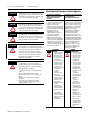
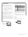
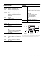
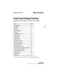
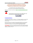
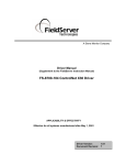
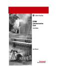
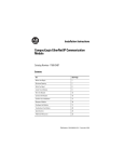
Installation Instructions
FLEX I/O EtherNet/IP Adapters
Important User Information
Identifies information about practices or
ATTENTION
circumstances that can lead to personal injury or
death, property damage, or economic loss.
Attentions help you identify a hazard, avoid a
hazard, and recognize the consequence
Cat. No. 1794-AENT, Series B
SHOCK HAZARD Labels may be on or inside the equipment (for
example, drive or motor) to alert people that
dangerous voltage may be present.
Important User Information
Solid state equipment has operational characteristics differing from
those of electromechanical equipment. Safety Guidelines for the
Application, Installation and Maintenance of Solid State Controls
(Publication SGI-1.1 available from your local Rockwell Automation sales
office or online at http://literature.rockwellautomation.com) describes
some important differences between solid state equipment and
hard-wired electromechanical devices. Because of this difference, and
also because of the wide variety of uses for solid state equipment, all
persons responsible for applying this equipment must satisfy themselves
that each intended application of this equipment is acceptable.
In no event will Rockwell Automation, Inc. be responsible or liable for
indirect or consequential damages resulting from the use or application
of this equipment.
The examples and diagrams in this manual are included solely for
illustrative purposes. Because of the many variables and requirements
associated with any particular installation, Rockwell Automation, Inc.
cannot assume responsibility or liability for actual use based on the
examples and diagrams.
No patent liability is assumed by Rockwell Automation, Inc. with respect
to use of information, circuits, equipment, or software described in this
manual.
Reproduction of the contents of this manual, in whole or in part, without
written permission of Rockwell Automation, Inc., is prohibited.
Throughout this manual we use notes to make you aware of safety
considerations.
Identifies information about practices or
WARNING
circumstances that can cause an explosion in a
hazardous environment, which may lead to
personal injury or death, property damage, or
economic loss.
IMPORTANT
Identifies information that is critical for successful
application and understanding of the product.
BURN HAZARD
ATTENTION
Labels may be on or inside the equipment (for
example, drive or motor) to alert people that
surfaces may reach dangerous temperatures.
Environment and Enclosure
This equipment is intended for use in a Pollution
Degree 2 industrial environment, in overvoltage
Category II applications (as defined in IEC publication
60664-1), at altitudes up to 2000 m (6562 ft) without
derating.
This equipment is considered Group 1, Class A
industrial equipment according to IEC/CISPR
Publication 11. Without appropriate precautions,
there may be potential difficulties ensuring
electromagnetic compatibility in other environments
due to conducted as well as radiated disturbance.
This equipment is supplied as open-type equipment.
It must be mounted within an enclosure that is
suitably designed for those specific environmental
conditions that will be present and appropriately
designed to prevent personal injury resulting from
accessibility to live parts. The enclosure must have
suitable flame-retardant properties to prevent or
minimize the spread of flame, complying with a flame
spread rating of 5VA, V2, V1, V0 (or equivalent) if
non-metallic. The interior of the enclosure must be
accessible only by the use of a tool. Subsequent
sections of this publication may contain additional
information regarding specific enclosure type ratings
that are required to comply with certain product
safety certifications.
Besides this publication, see:
• Industrial Automation Wiring and Grounding
Guidelines, for additional installation
requirements, Allen-Bradley publication
1770-4.1.
• NEMA Standards publication 250 and IEC
publication 60529, as applicable, for explanations
of the degrees of protection provided by different
types of enclosure.
2
FLEX I/O EtherNet/IP Adapters
WARNING
WARNING
WARNING
ATTENTION
ATTENTION
Installation Instructions
When you insert or remove the module while
backplane power is on, an electrical arc can occur.
This could cause an explosion in hazardous location
installations. Be sure that power is removed or the
area is nonhazardous before proceeding.
If you connect or disconnect the communications
cable with power applied to this module or any
device on the network, an electrical arc can occur.
This could cause an explosion in hazardous location
installations. Be sure that power is removed or the
area is nonhazardous before proceeding.
If you connect or disconnect wiring while the
field-side power is on, an electrical arc can occur.
This could cause an explosion in hazardous location
installations. Be sure that power is removed or the
area is nonhazardous before proceeding.
This product is grounded through the DIN rail to
chassis ground. Use zinc-plated yellow-chromate
steel DIN rail to assure proper grounding. The use of
other DIN rail materials (such as aluminum or
plastic) that can corrode, oxidize, or are poor
conductors, can result in improper or intermittent
grounding. Secure DIN rail to mounting surface
approximately every 200 mm (7.8 in.) and use
end-anchors appropriately.
Prevent Electrostatic Discharge
This equipment is sensitive to electrostatic
discharge, which can cause internal damage and
affect normal operation. Follow these guidelines
when you handle this equipment:
• Touch a grounded object to discharge potential
static.
• Wear an approved grounding wriststrap.
• Do not touch connectors or pins on component
boards.
• Do not touch circuit components inside the
equipment.
• Use a static-safe workstation, if available.
• Store the equipment in appropriate static-safe
packaging when not in use.
Publication 1794-IN082C-EN-P - October 2007
North American Hazardous Location Approval
The following information
applies when operating this
equipment in hazardous
locations.
Products marked “CL I, DIV 2, GP A,
B, C, D are suitable for use in Class
I Division 2 Groups A, B, C, D,
hazardous locations and
nonhazardous locations only. Each
product is supplied with markings
on the rating nameplate indicating
the hazardous location
temperature code. When
combining products within a
system, the most adverse
temperature code (lowest “T”
number) may be used to help
determine the overall temperature
code of the system. Combinations
of equipment in your system are
subject to investigation by the
local Authority Having Jurisdiction
at the time of installation.
WARNING
EXPLOSION
HAZARD
• Do not disconnect
equipment unless
power has been
removed or the
area is known to be
nonhazardous.
• Do not disconnect
connections to this
equipment unless
power has been
removed or the
area is known to be
nonhazardous.
Secure any
external
connections that
mate to this
equipment by using
screws, sliding
latches, threaded
connectors, or
other means
provided with this
product.
• Substitution of
components may
impair suitability
for Class I, Division
2.
• If this product
contains batteries,
they must only be
changed in an area
known to be
nonhazardous.
Informations sur l’utilisation de
cet équipement en
environnements dangereux .
Les produits marqués “CL I, DIV 2,
GP A, B, C, D” ne conviennent qu’à
une utilisation en environnements
de Classe I Division 2 Groupes A, B,
C, D dangereux et non dangereux.
Chaque produit est livré avec des
marquages sur sa plaque
d’identification qui indiquent le
code de température pour les
environnements dangereux.
Lorsque plusieurs produits sont
combinés dans un système, le code
de température le plus défavorable
(code de température le plus faible)
peut être utilisé pour déterminer le
code de température global du
système. Les combinaisons
d’équipements dans le système
sont sujettes à inspection par les
autorités locales qualifiées au
moment de l’installation.
RISQUE
AVERTISSEMENT
D’EXPLOSION
• Couper le courant
ou s’assurer que
l’environnement
est classé non
dangereux avant
de débrancher
l'équipement.
• Couper le courant
ou s'assurer que
l’environnement
est classé non
dangereux avant
de débrancher les
connecteurs. Fixer
tous les
connecteurs
externes reliés à
cet équipement à
l'aide de vis,
loquets
coulissants,
connecteurs
filetés ou autres
moyens fournis
avec ce produit.
• La substitution de
composants peut
rendre cet
équipement
inadapté à une
utilisation en
environnement de
Classe I, Division
2.
• S’assurer que
l’environnement
est classé non
dangereux avant
de changer les
piles.
FLEX I/O EtherNet/IP Adapters
8
2
3
22
5. If necessary, push up on the locking tab to lock.
7
++
6
4
5
3
4. If the adapter does not lock in place, use a
screwdriver or similar device to move the locking
tab down while pressing the adapter flush onto the
DIN rail: releasing the locking tab to lock the
adapter in place.
EtherNet/IP Adapter, Cat. No. 1794-AENT
1
Installation Instructions
6. Connect the adapter wiring as shown under
Connecting Wiring later in this document.
9
Component Identification
1
EtherNet/IP adapter
2
Status indicators
3
MAC ID label
4
Network cable RJ45 connector (underside)
5
Adapter DIN rail locking tab
6
24V dc connections
7
24V common connections
8
Flexbus connector
9
IP address switches
Mount or Replace the Adapter on an Existing
System
1. Remove the Ethernet plug-in connector from the
bottom of the adapter.
2. Disconnect any adapter wiring jumpered to the
adjacent terminal base.
3. Disconnect any user power wiring connections to
the adapter.
Install Your Adapter Module
A
B
1794-AENT/B
22
++
C
Mount on a DIN Rail Before Installation of the
Terminal Base Units
4. Using a screwdriver or similar tool, open the
module locking mechanism and remove the
module from the base unit to which the adapter
will be attached.
5. Push the Flexbus connector toward the right side
of the terminal base to unplug the backplane
connection.
Make certain the Flexbus connector is completely
clear of the adapter. The slide must be completely to
the right and the raised spot on the slide visible.
ATTENTION
1. Hook the lip on the rear of the adapter (A) onto
the top of the 35 x 7.5 mm DIN rail (B).
Terminal base of I/O
module adjacent to
the 1794-AENT
adapter.
2. Rotate the adapter module onto the rail.
3. Press the adapter down onto the DIN rail until
flush.
22
++
31244CC
DIN rail locking tab (C) will snap into position
and lock the adapter to the DIN rail.
Locking Tab C
6. Release the DIN rail locking tab (C) and remove
the adapter.
Publication 1794-IN082C-EN-P - October 2007
4
FLEX I/O EtherNet/IP Adapters
Installation Instructions
Before installing the new adapter, notice the notch on the
right rear of the adapter. This notch accepts the hook on
the terminal base unit. The notch is open at the bottom.
The hook and adjacent connection point keep the
terminal base and the adapter tight together, reducing the
possibility of a break in communication over the
backplane.
1. Connect the Ethernet network cable to the RJ45
connector (A) on the underside of the adapter.
A
2
+ + 2
+
31247-M
IMPORTANT
7. Complete the adapter mounting as shown below.
Push down and in at the same time
to lock the adapter to the DIN rail.
When the adapter is locked onto the DIN
rail, gently push the Flexbus connector into
the adapter to complete the backplane.
We recommend connecting the module to the
network via a 100 MB full-duplex switch, which will
reduce network collisions and lost packets, and
increase bandwidth. For detailed Ethernet
connection information, see these publications:
• Ethernet/IP Performance and Application Guide,
publication ENET-AP001
• Ethernet/IP Media Planning and Installation
Guide, publication number ENET-IN001
• Precautions to Increase the Noise Immunity of
the 1794-AENT FLEX I/O Ethernet/IP Adapter
System, KnowBase Technote ID 42604
22
++
31244-M
8. If the adapter does not lock in place, use a
screwdriver or similar device to move the locking
tab down while pressing the adapter flush onto the
DIN rail: releasing the locking tab to lock the
adapter in place.
If necessary, push up on the locking tab to lock.
9. Reinstall the module in the adjacent terminal base
unit.
Connect Wiring
WARNING
If you connect or disconnect the communication
cable with power applied to the adapter or any
device on the network, an electrical arc can occur.
This could cause an explosion in hazardous location
installations. Be sure that power is removed or the
area is nonhazardous before proceeding.
D
B
1794-AENT/B
31246-M
A
C
E
Publication 1794-IN082C-EN-P - October 2007
2. Connect 24V common to the left side of the upper
connector, terminal B.
IMPORTANT
Do not wire more than 2 conductors on any single
terminal.
When connecting wiring, torque terminal screws B,
C, D, and E to 0.8 Nm (7 lb-in).
3. Connect +24V dc input power to the left side of
the lower connector, terminal C.
4. Use connectors D and E to pass 24V common
(D) and 24V dc power (E) to the next module in
the series.
FLEX I/O EtherNet/IP Adapters
Set the Network Address
The adapter ships with the thumbwheel switches set to
999 and DHCP enabled. You can set the network
Internet Protocol (IP) address in these ways:
• Use the thumbwheel switches on the module.
• Use a Dynamic Host Configuration Protocol
(DHCP) server, such as Rockwell Automation
BootP/DHCP.
• Retrieve the IP address (if previously set) from
nonvolatile memory.
The adapter reads the thumbwheel switches first to
determine if the switches are set to a valid number. You
set the node address by using the three-position
thumbwheel switch. Press the + or - buttons to change
the number. Valid settings are 001…254.
When the switches are set to a valid number, the adapter’s
IP address is 192.168.1.xxx (where xxx represents the
number set on the switches). The adapter’s subnet mask
is 255.255.255.0 and the gateway address is set to 0.0.0.0.
The adapter does not have a host name assigned, or use
any Domain Name System when using the thumbwheel
settings.
Network Address Thumbwheel
Installation Instructions
5
If you set the switches to an invalid number (such as 000,
or a value greater than 254), the adapter checks to see if
you enabled DHCP.
DHCP Enabled and Not Enabled
If DHCP is
Then the adapter
Enabled
Asks for an address from a DHCP server. The
DHCP server also assigns other Transport Control
Protocol (TCP) parameters.
Not enabled
Uses the IP address (along with other TCP
configurable parameters) stored in nonvolatile
memory.
The switch value of 888 lets you reset all configuration
parameters to the factory settings. This is useful in
situations where you want to reuse a module that has an
unknown configuration.
Refer to the EtherNet/IP Adapter User Manual,
publication ENET-UM001, for more information.
Indicators
The faceplate of the 1794-AENT adapter is provided
with three bicolor indicators.
Module Status
Network Status
Network Address
Thumbwheel Press Either the + or Buttons to Change the
Number
Link Status
22
++
Publication 1794-IN082C-EN-P - October 2007
6
FLEX I/O EtherNet/IP Adapters
Installation Instructions
Module Status Indicators
Indicator
Module
Status
Indicator
Status
Off No Power
Flashing
Green Standby
Green Operational
Flashing Red
- Minor Fault
Red Major Fault
Flashing Red
and Green Self Test
Description
Adapter does not have 24V dc power.
Make sure power is being supplied to the
adapter.
Adapter not configured.
Configure adapter.
Adapter operating correctly.
No action required.
A recoverable fault has been detected.
This could be caused by an incorrect or
inconsistent configuration.
Check configuration and reconfibure as
needed.
An unrecoverable fault has been detected.
Recycle power to the adapter. If this does
not clear the fault, replace the adapter.
Adapter performing power-up self test.
Wait until completed.
Network Status Indicators
Indicator
Network
Status
Indicator
Status
Description
Off Adapter is not powered, or does not have
Not Powered, an IP address.
No IP
• Verify there is power and the adapter
Address
is correctly wired to the power supply.
• Make sure the adapter is configured.
Adapter has obtained an IP address, but
Flashing
Green has no established connections.
No
Connections.
Green Adapter has an IP address and at least one
CIP
established connection.
Connections
Flashing Red One or more of the connections in which
the adapter is the target has timed out.
Connection
Timeout
Red Adapter has detected that its IP address is
Duplicate IP already in use. Configure the adapter with
Address
a unique IP address.
Flashing Red Adapter performing power-up self test.
and Green Self Test
Specifications
FLEX I/O EtherNet/IP Adapter - 1794-AENT
Attribute
Value
I/O capacity
8 modules
Power supply
To comply with the CE Low Voltage Directive (LVD),
this equipment must be powered from a source
compliant with the following:
Safety Extra Low Voltage (SELV) or Protected Extra
Low Voltage (PELV).
Input voltage rating
24V dc nom
Input voltage range
19.2…31.2V dc (includes 5% ac ripple)
Communication rate 10/100 Mbps
Indicators
Module Status - red/grn
Network Status - red/grn
Link Status - grn
Flexbus output
current
640 mA max
Isolation voltage
50V continuous, Basic Insulation Type
Tested at 1000V ac for 60 s, power to Flexbus to
EtherNet
Power consumption
550 mA max, 440 mA max at 24V dc
Power dissipation
7.3 W max @ 19.2V dc
Thermal dissipation
24.9 BTU/hr @ 19.2V dc
Ethernet connector
RJ45 Cat. 5
Enclosure type rating None (open-style)
North American
temp code
Power conductors
Wire size
Status
Off No link
exists.
Flashing
Green I/O is being
transmitted
or received.
Steady Green
- A link
exists.
Description
Verify network cabling. Correct as
necessary.
Normal operation. No action required.
Publication 1794-IN082C-EN-P - October 2007
0.34…2.5 mm2 (22…12 AWG) stranded copper
wire rated at 75 °C (167 °F) or higher, 1.2 mm (3/64
in.) insulation max
Category(1)
1 - on power ports
2 - on communications ports
Terminal screw
torque
0.8 Nm (7 lb-in)
Publications(2)
User Manual ENET-UM001
(1)
You use this category information for planning conductor routing as described in
Allen-Bradley Industrial Automation Wiring and Grounding Guidelines,
publication 1770-4.1.
(2)
For additional installation information, refer to ODVA EtherNet/IP Media
Planning and Installation manual, publication 148 at http://www.odva.org, and
document number 42604 in Rockwell Automation Knowledgebase at
http://rockwellautomation.com/knowledgebase.
Link Status Indicator
Indicator
Link Status
Indicator
T4A
FLEX I/O EtherNet/IP Adapters
Environmental Specifications
Value
Temperature,
operating
IEC 60068-2-1 (Test Ad, Operating Cold),
IEC 60068-2-2 (Test Bd, Operating Dry Heat),
IEC 60068-2-14 (Test Nb, Operating Thermal Shock):
0…55 °C (32…131 °F)
Temperature,
nonoperating
IEC 60068-2-1 (Test Ab, Unpackaged Nonoperating
Cold),
IEC 60068-2-2 (Test Bb, Unpackaged Nonoperating Dry
Heat),
IEC 60068-2-14 (Test Na, Unpackaged Nonoperating
Thermal Shock):
–40…85 °C (–40…185 °F)
Relative
humidity
IEC 60068-2-30 (Test Db, Unpackaged Nonoperating
Damp Heat):
5…95% noncondensing
Vibration
IEC60068-2-6 (Test Fc, Operating):
5 g @ 10…500 Hz
Value
(when product
is marked(1)
c-UL-us
UL Listed Industrial Control Equipment, certified for
US and Canada (See UL file E65584)
UL Listed for Class I, Division 2, Groups A, B, C and D
Hazardous locations, certified for US and Canada (See
UL file E194810)
CE
European Union 2004/108/EEC EMC Directive,
compliant with:
EN 61326; Meas./Control/Lab., Industrial
Requirements
EN 61000-6-2; Industrial Immunity
EN 61000-6-4; Industrial Emissions
EN61131-2; Programmable Controllers (Clause 8, Zone
A & B)
C-Tick
Australian Radiocommunications Act compliant with
AS/NZS CISPR 11, Industrial Emissions
EtherNet/IP
ODVA conformance tested to EtherNet/IP
specifications
Shock, operating IEC60068-2-27 (Test Ea, Unpackaged shock):
30 g
(1)
Shock,
nonoperating
IEC60068-2-27 (Test Ea, Unpackaged shock):
50 g
Emissions
CISPR 11:
Group 1, Class A
ESD immunity
IEC 61000-4-2:
6 kV contact discharges
8 kV air discharges
Radiated RF
immunity
IEC 61000-4-3:
10 V/m with 1 kHz sine-wave 80% AM from 80…2000
MHz
10 V/m with 200 Hz 50% Pulse 100% AM at 900 MHz
10 V/m with 200 Hz 50% Pulse 100% AM at 1890 MHz
3 V/m with 1 kHZ sine-wave 80% AM from
2000…2700MHz
EFT/B immunity
IEC 61000-4-4:
±4 kV at 5 kHz on power ports
±2 kV at 5 kHz on communication ports
Surge transient
immunity
IEC 61000-4-5:
±1 kV line-line (DM) and ±2 kV line-earth (CM) on power
ports
±2 kV line-earth (CM) on communication ports
Conducted RF
immunity
IEC 61000-4-6:
10V rms with 1 kHz sine-wave 80% AM from 150
kHz…80 MHz
7
Certifications
Certification
Attribute
Installation Instructions
See the Product Certification link at http://www.ab.com for Declarations of Conformity, Certificates and
other certification details.
Mounting Dimensions
B
50
(2.2)
87
(3.4)
80
(3.2)
30
(1.2)
94
(3.7)
1794-AENT
87H x 94W x 69D
(3.4H x 3.7W x 2.7D)
A = DIN rail.
B = Secure DIN rail approximately every 200 mm (7.87 in.).
A
mm
(in.)
Flex I/O, Allen-Bradley, ControlLogix, Rockwell Automation, RSLogix 5000, and RSLinx are trademarks
of Rockwell Automation, Inc.
Trademarks not belonging to Rockwell Automation are property of their respective companies.
Publication 1794-IN082C-EN-P - October 2007
Rockwell Automation Support
Rockwell Automation provides technical information on the Web to assist you in using its products. At
http://support.rockwellautomation.com, you can find technical manuals, a knowledge base of FAQs, technical and
application notes, sample code and links to software service packs, and a MySupport feature that you can customize to
make the best use of these tools.
For an additional level of technical phone support for installation, configuration, and troubleshooting, we offer
TechConnect support programs. For more information, contact your local distributor or Rockwell Automation
representative, or visit http://support.rockwellautomation.com.
Installation Assistance
If you experience a problem within the first 24 hours of installation, please review the information that's contained in
this manual. You can also contact a special Customer Support number for initial help in getting your product up and
running.
United States
1.440.646.3434
Monday – Friday, 8am – 5pm EST
Outside United States
Please contact your local Rockwell Automation representative for any technical support issues.
New Product Satisfaction Return
Rockwell Automation tests all of its products to ensure that they are fully operational when shipped from the
manufacturing facility. However, if your product is not functioning and needs to be returned, follow these procedures.
United States
Contact your distributor. You must provide a Customer Support case number (see phone number above to obtain one) to your
distributor in order to complete the return process.
Outside United States
Please contact your local Rockwell Automation representative for the return procedure.
Publication 1794-IN082C-EN-P - October 2007 8
Supersedes Publication 1794-IN082B-EN-P - February 2004
PN 15812
Copyright © 2007 Rockwell Automation, Inc. All rights reserved. Printed in the U.S.A.