1
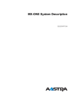
MAINTENANCE
1541-DBC
02
12
2013
H6
425 01INSTRUCTIONS
IP telephone DBC 42x
Catarina
Tero
csten
BES/DDC
EBC
Silvennoinen
Sten
MAINTENANCE INSTRUCTIONS
IP TELEPHONE DBC 42X
Copyright
© Copyright Aastra Technologies Limited, 2013. All rights reserved.
Disclaimer
No part of this document may be reproduced in any form without the
written permission of the copyright owner.
The contents of this document are subject to revision without notice due
to continued progress in methodology, design and manufacturing.
Aastra shall have no liability for any error or damage of any kind resulting
from the use of this document.
2
1541-DBC 425 01 Uen H6 2013-12-02
GENERAL
1
General
This document is to be used by service personnel when maintaining the
IP telephones DBC 420 02, DBC 422 01, DBC 422 02, DBC 425 01 or
DBC 425 02. They are henceforth referred to as DBC 42x.
Table 1
Hardware faults in DBC 42x should not be repaired locally, except
for replacement of parts listed in the spare part list. The purpose of
the following instructions is to decide whether there is a hardware
fault in the IP telephone or not.
If a hardware fault occurs in DBC 42x, the unit shall be returned to
Aastra Global Service Logistics Centre.
If there is a fault in the software of the telephone, the software can be
updated on site, see installation instructions for DBC 420, installation
instructions for DBC 422 or installation instructions for DBC 425.
For information about spare parts, see spare part list for TELEPHONE
SETS DBC 220+.
2
Self-tests
There are two types of self-tests, one is automatic and the other manual.
2.1
Automatic self-test
After booting, the telephone performs an automatic self-test of the hardware.
If no faults are detected the text Self test OK is shown in the display for
one second and the LED in the third key from the bottom in the left row
is lit (only LED indication for DBC 420).
If a fault is detected the Self test OK is not shown in the display, neither
will the LED be turned on. Check that the power supply works, and if the
text Self test OK still does not occur, it is a hardware fault.
1541-DBC 425 01 Uen H6 2013-12-02
3
IP TELEPHONE DBC 42X
2.2
Manual self-test (initiated with C * 4)
This test is initiated by pressing the keys C (Clear-key), * and 4 simultaneously for one second. The program revision is shown in the display
for 5 seconds and then all the pixels and LEDs are lit for one minute. To
terminate the self-test press the # key. To read out the program revision
for DBC 420 the Web interface must be used.
The following objects are tested automatically:
1)
Data registers in the line analogue audio interface circuit
2)
LEDs (light up)
3)
The display hardware (all existing characters appears in the
display), not DBC 420.
4)
The versions of the application and the bootROM (appear in the
display), not DBC 420.
5)
The configuration file (if the configuration file is faulty, this is indicated on the display, for DBC 420 the LED in the first key from the
bottom in the left row is lit).
In addition, the following objects can be tested: keys, hook, LEDs, tone
ringer, display and speech transmission, see below.
2.2.1
Manual self-test mode result
If no faults are found, the display shows (this is an example from DBC
425 02):
Figure 1:
In the example the bootROM firmware has the product number CAA 158
00 44 and the version is R1A . For the application firmware and the
language file, the product number and version are shown as well.
4
1541-DBC 425 01 Uen H6 2013-12-02
SELF-TESTS
This menu is shown in the display for about 5 seconds and then all the
pixels and LEDs are lit for one minute. To terminate the self-test press
the # key.
If a fault is found, an error message will appear on the display, see 2
Error messages presented on the display on page 5.
Table 2 Error messages presented on the display
ERROR MESSAGE
written in the display
Measure
ERROR: LCD (if
possible) *1)
Replace the telephone
ERROR: DSP *2)
Replace the telephone
ERROR: Codec *3)
Replace the telephone
ERROR: Config file *4)
Make corrections in the configuration
file and enter the file again. See the
description for CONFIGURATION FILE
FOR DBC 42X
*1) Not for DBC 420 02, DBC 422 01 and DBC 422 02
*2) Not for DBC 420 02, DBC 422 02 and DBC 425 02
*3) Not for DBC 420 02, DBC 422 02 and DBC 425 02
*4) Not for DBC 420 02
2.2.2
Keys, hook switch and tone ringer test
The keys can be tested by pressing them one at a time. Each keystroke
should generate a tone signal.
A tone signal is generated when lifting the handset and replacing it
again.
The volume of the tone ringer can be changed by pressing the volume
keys marked + and - . The level will be retained upon exiting the Manual
self-test mode.
1541-DBC 425 01 Uen H6 2013-12-02
5
IP TELEPHONE DBC 42X
2.2.3
Local speech and transmission test
2.2.3.1
Handset function
Lift the handset to activate the handset mode. The microphone signal in
the handset is sent via the audio circuit and is looped back in the DSP to
the handset receiver. To test the handset transmission:
2.2.3.2
1.
Blow into the handset microphone.
2.
Listen for the sound in the handset receiver.
Handsfree microphone (only DBC 422 02, DBC 425 01 and DBC 425
02)
To test the handsfree microphone:
2.2.3.3
1.
Press the loudspeaker key.
2.
Keep the handset on hook.
3.
Knock near the handsfree microphone.
4.
Listen to the knocking sound in the loudspeaker.
Volume control
The volume of each transmission mode can be changed by pressing the
volume keys marked + and - . If the volume is adjusted when the telephone is in the test mode, the volume selected will be retained upon
exiting the test mode.
2.2.3.4
Mute function
The mute function is tested by pressing the Mute key while blowing into
the microphone and checking if the sound in the handset receiver or
loudspeaker ceases.
3
Restart the telephone
It is possible to restart the telephone manually by pressing the keys C
(Clear-key), # and mute simultaneously for 1 second. This is called a
software reboot. If a lock up problem shall be isolated, it is useful to do
6
1541-DBC 425 01 Uen H6 2013-12-02
RESTART THE TELEPHONE
the Telnet / SSH command showLog, see 4.1.2.3 To print recent events
on page 10.The log will be kept after the software reboot.
If the software reboot does not restart the telephone and the log shall be
kept, press the reset button. The reset button can be reached via one of
the hollows for the foot consoles using a thin object, i.e. a screwdriver,
see 2 Position of reset button on the DBC 42x telephones on page 7 .
This is called a hardware reboot.
If the software reboot does not restart the telephone and the log is not of
any interest, reboot the telephone by doing a power reboot.
Figure 2: Position of reset button on the DBC 42x telephones
1541-DBC 425 01 Uen H6 2013-12-02
7
IP TELEPHONE DBC 42X
4
Log on to the IP telephone from a
PC
For maintenance and fault locating purposes, it is possible to log on to
the IP telephone in two ways:
4.1
1)
Telnet / SSH, see below. Use the Telnet / SSH window in a PC and
enter the IP address of the telephone. Via Telnet / SHH the
complete set of commands and log functions can be used.
2)
The web-server in the telephone. Use a web-browser in a PC and
enter the web address of the telephone into the address field in the
web-browser, see 4.2 Web server on page 11. Via the web-server
only a limited set of commands/functions and no continuous log
functions can be used.
Telnet / SSH
The system administrator can from a PC access the telephone in one of
the following ways:
1)
Telnet. Only DBC 42x 01 and in DBC 42x 02 using the application
versions before R4A.
2)
SSH (Secure Shell). Only DBC42x 02 using the application
versions R4A or later. This interface is similar to the Telnet interface, but the connection is secure.
In the maintenance PC, a SSH client must be used. There are a
number of free-ware clients, the must popular is PuTTY for PCs
with Windows®.
The default encryption keys are used and not possible to change.
To know the IP address of the telephone, select the Settings and the
Network menu. For DBC 420 02 the IP address can be obtained from the
IP Phone Administrator, see 8 IP Phone Administrator on page 19 .
The procedure to log on is:
8
1.
Open a Telnet / SSH session and enter the IP address of the telephone. The login prompt will appear. The commands are case
sensitive.
2.
VxWorks login: admin
3.
(default) Password: Telephone
1541-DBC 425 01 Uen H6 2013-12-02
LOG ON TO THE IP TELEPHONE FROM A PC
4.
To get a list with existing commands, key the command Help
5.
Enter the desired command.
6.
The desired logging level of printouts can be chosen
The procedure for changing password, see installation instructions for
DBC 425.
4.1.1
Commands
To get a list with the existing commands and an explanation of each
command, enter the command Help .
4.1.2
Event Logs
It is possible to obtain a log file of events. These events are printed from
either:
1)
The application software. These events are printed from different
modules in the application.
2)
The operating system. These events are stored in the run-time
error record log and in the so called post-mortem event log.
The log file can be attached to the fault report and analysed by the level
three support. The log shall not be interpreted by the maintenance
personnel.
It is possible to select the level of events from the different parts of the
software in the telephone:
gWAPDebug
The events that occur in the WAP module in the telephone. This
module handles services and display messages. This command is
only valid when the gatekeeper supports WAP.
gUIDebug
The events that occur in the user interface module in the telephone.
gH323Debug
The events that occur in the H.323 stack module in the telephone.
gRTPDebug
The events that occur in the voice (media stream) module in the
telephone.
gWEBDebug
The events that occur in the web server.
gOMDSigDebug
The events that occur in OMD mode.
1541-DBC 425 01 Uen H6 2013-12-02
9
IP TELEPHONE DBC 42X
For each of the commands above 4 different levels of stored events can
be set. The following levels exist:
0 = No events are printed
1 = Messages that most likely are errors, are printed
2 = Selected events are printed
3 = All events are printed
For detailed description key the command Help .
These commands work through the web-server as well.
4.1.2.1
To print the IP addresses and the status for the telephone
To print the IP addresses and the status for the telephone, enter the
command:
phoneStatShow
4.1.2.2
To display the events as they occur
Log on via Telnet / SSH as described above. The events are displayed
as they occur in the telephone.
4.1.2.3
To print recent events
It is also possible to retrieve the most recent events in the telephone.
That could also be events that occurred before logging on to the telephone with Telnet / SSH. The event log offers 4000 lines and is obtained
by open a log file in the PC, log on the telephone and enter the following
Telnet /SSH command:
showLog
This log is kept even when the telephone is restarted, but is lost after loss
of power. This command works through the web-server as well, see
4.2.3 To use the functions in the web interface on page 15.
4.1.2.4
To print events stored in the flash memory
The watchdog function, see 7 Watchdog on page 19 , can store the last
events in the flash memory. The command for printing the log from the
flash memory is:
showFlashLog
The log is over-written next time the watchdog is activated.
10
1541-DBC 425 01 Uen H6 2013-12-02
LOG ON TO THE IP TELEPHONE FROM A PC
4.1.2.5
Run-time error record log
This log shows the run-time error records (up to the last 7) detected by
the operating system. The log is cleared at hardware reboot. Examples
of recorded events are: bound-check errors, violations of memory
blocks, pointer arithmetic errors etc. The command for printing the log is:
edrShow
4.1.2.6
Post-mortem event log
This log contains the function calls to the operating system in the telephone. In this log it is possible to analyse what happened in the operating system before a crash occurred in the telephone. This log is saved
even after a restart of the telephone, but not after loss of power.
Log on to the telephone as described in section above. Start the
post-mortem log by entering the Telnet / SSH command:
startEventLog
After this it is possible to log off and wait until the problem in the telephone occurs. To up-load the post-mortem log to the PC:
4.2
1.
Install the program EventReceive on the PC. Please contact your
Aastra service office to obtain this program.
2.
Log on to the telephone via Telnet / SSH
3.
Stop the log and up-load the log to the PC by typing the command
startEventUpload "IP address of the PC" example: startEventUpload "153.81.8.140"
4.
In the GUI of EventReceive , it is possible to choose (by pressing
Setup ) where to save the log file which has the file extension .wvr
5.
Send the file to Aastra which has the special program needed to
open the file.
Web server
It is possible to access the IP telephone from a web browser in a PC. The
following can be done:
1)
Debug log: display 4000 lines of the most recent events in the telephone.
2)
Debug level: select the level of events from the different parts of the
software in the telephone, see 4.1.2 Event Logs on page 9 . This
must be chosen before the trace (debug log) is done.
1541-DBC 425 01 Uen H6 2013-12-02
11
IP TELEPHONE DBC 42X
3)
Settings: log off restriction. In conference rooms etc. to restrict the
log off possibility: default number used or permit individual log on.
4)
Settings: change the end user password for the web server. That is
the password a user uses to access the web server.
5)
Settings: view and change network addresses: the telephone’s IP
address, subnet mask, default gateway, web server, if DHCP shall
be used or not and if the web server address received via DHCP
shall be used or not. The telephone will reboot if anything is
changed here.
6)
Settings: view and change if automatic gatekeeper discovery shall
be used.
7)
Settings: view and change the gatekeeper IP address(es)
8)
Settings: show voice quality of service (QoS) values
9)
Settings: show the telephone’s configuration
10) Settings: view and change the programmable keys
11) Settings: view and change if the impaired hearing level should be
on or off
12) Settings: view and change the tone ringer character
The IP address or the web address (URL) to the telephone has to be
entered in the address field in the web browser. The way to find the IP
address and the web address is described below.
4.2.1
Access to the web interface with the web address (URL)
The web address (URL) is the host- and domain name received from the
DHCP server. To find out the web address, go to the Settings menu and
select Network . The web address is the second and the IP address is
the third item in the list.
For DBC 420 the IP address must be used instead of the web address
and it can be obtained from the IP Phone Administrator, see 8 IP Phone
Administrator on page 19 .
12
1541-DBC 425 01 Uen H6 2013-12-02
LOG ON TO THE IP TELEPHONE FROM A PC
Figure 3:
Example from DBC 425 01
The arrow shows which line to use. This web address should be entered
in the address field in the web-browser in the PC. Example:
http://pc123-45.ab.cde.fghijk.lm
When the page is loaded, the following will be shown in the web browser:
Figure 4:
If the access to this web page fails when using an earlier used web
address, check the web address on the display in the telephone. If the
telephone has been disconnected from the LAN for a couple of days, this
web address might have changed.
1541-DBC 425 01 Uen H6 2013-12-02
13
IP TELEPHONE DBC 42X
The description of the functions in the web interface, see 4.2.3 To use
the functions in the web interface on page 15 .
4.2.2
Access to the web interface with the IP address
If the IP address shall be used in the web browser to access the web
interface in the telephone, go to the Settings menu and select Network.
The IP address is the second item in the list.
For DBC 420 the IP address can be obtained from the IP Phone Administrator, see 8 IP Phone Administrator on page 19 .
Figure 5:
Example from DBC 425 01
The arrow shows which line to use. This IP address should be entered
in the address field in the web-browser in the PC. Example:
http://153.88.8.192
In the web browser, the following will be shown:
14
1541-DBC 425 01 Uen H6 2013-12-02
LOG ON TO THE IP TELEPHONE FROM A PC
Figure 6:
The description of the functions in the web interface, see 4.2.3 To use
the functions in the web interface on page 15 .
If the page is not shown, a change in the proxy settings in the web
browser in the PC may be needed.
4.2.3
To use the functions in the web interface
Log on to the telephone. Use the password Telephone (for DBC42x02
and DBC42x01). The password is case sensitive. This password can be
changed, see installation instructions for DBC 420, installation instructions for DBC 422 or installation instructions for DBC 425.
This password is not the same as the password used to log on the telephone to the exchange. Click on the log on button.
The next menu is:
1541-DBC 425 01 Uen H6 2013-12-02
15
IP TELEPHONE DBC 42X
Figure 7:
Click on the plus signs to show the sub menus and then click on the
desired function.
4.2.3.1
Show QoS values (Only for the H.323 protocol)
When clicking on Show Voice QoS Values the statistics of the last ten
calls are shown.
16
1)
B-Party Phone number , the telephone number of the remote
party.
2)
Call Start Time , date and time of when the call started.
3)
Call Duration , the duration of the call in seconds.
4)
Other Endpoint IP Address , the IP address of the remote IP telephone for non gateway calls, the IP address of the gateway for
gateway calls.
5)
Used Codec , the voice codec that was used in the call.
6)
Cumulative Packets Lost , the total amount of incoming lost
packets during the call. Should be less than about 40 packets for a
normal call (1 minute).
1541-DBC 425 01 Uen H6 2013-12-02
LOG ON TO THE IP TELEPHONE FROM A PC
7)
Delay , the RTCP end to end round trip delay divided by two, in
milliseconds. Example: If the delay from the telephone to the
gateway is 100 ms and from the gateway to the telephone 80 ms,
the showed value will be (100 + 80)/2 = 90 ms. The average value
should be less than 50 ms and the maximum value should be less
than 250 ms.
8)
Jitter , according to the standard H.460.9, in milliseconds. The
average value should be less than 90 ms and the maximum value
should be less than 200 ms.
9)
Packet Loss Rate , number of incoming packets lost per second.
The maximum value should be less than 1 packet/s.
If the maximum or average values in bullets 6 - 9 are exceeded, there is
most likely a problem in the LAN.
4.2.3.2
Show phone configuration
When clicking on Show Phone Configuration the configuration in the
telephone is shown.
The data below the heading Configuration file displays the entire
configuration file, but without the comments. The data below the heading
Status shows some additional information like the current versions, the
telephone number, the software server and the domain name from
DHCP.
4.2.3.3
Delete phone book (DBC 422 02, DBC 425 01 and DBC 425 02 only)
The function for the sub menu in the Task folder, deletes all entries in
the phone book. A warning dialogue window is displayed and when
clicking OK in that dialogue, the phone book will be permanently erased.
This can be used when a telephone shall be used by another end user.
4.2.3.4
Delete user’s name (DBC 422 01 only)
The function for the sub menu in the Task folder, deletes the user’s
name that is shown when the telephone is in idle mode. A warning
dialogue window is displayed and when clicking OK in that dialogue, the
user’s name will be permanently erased. This can be used when a telephone shall be used by another end user.
1541-DBC 425 01 Uen H6 2013-12-02
17
IP TELEPHONE DBC 42X
5
Reset of Data Settings
5.1
Factory Default
Only DBC 42x 02. To set the telephone to factory default, the following
procedure must be used:
1.
Log off.
2.
Enter administrator mode, see 6 Administrator mode on page 19.
3.
Press the keys C,*,9 for a second.
The following data will be set:
5.2
1)
Use DHCP
2)
Retrieve the IP address to the software server automatically (from
DHCP or DNS SRV resource records)
3)
Automatic VLAN detection
4)
Automatic detection of LAN access control according to
IEEE802.1x
5)
The contact list is erased
6)
All the numbers associated to function keys are erased.
7)
All the function keys are placed on the default positions, see the
description for CONFIGURATION FILE FOR DBC 42X.
8)
Increased hearing level is set to standard.
Reset Network Settings
From the web interface it is possible to reset the network settings. Press:
Settings > Network > Reset Network Setting
The following data will be reset:
18
•
Use DHCP.
•
Retrieve the IP address to the software server automatically
(from DHCP or DNS SRV resource records).
•
The current VLAN settings will be erased. Automatic VLAN
detection will be enabled.
1541-DBC 425 01 Uen H6 2013-12-02
ADMINISTRATOR MODE
6
•
Automatic detection of LAN access control according to
IEEE802.1x.
•
Automatic gatekeeper discovery.
Administrator mode
The administrator mode is used when IP settings is to be changed.
To enter the administrator mode: go to the Settings menu and then
press the keys C (clear key), * and 5 simultaneously for one or two
seconds. One ringing signal is heard to indicate that this mode is
entered. The administrator mode is valid until exiting from the Settings
menu.
7
Watchdog
There is a software watchdog function to avoid lock up of the telephone.
When the watchdog function is activated, the last 400 lines in the event
log are stored in the flash memory and the telephone performs a re-boot.
The procedure for printing the log from the flash memory, 4.1.2.4 To print
events stored in the flash memory on page 10 .
8
IP Phone Administrator
The tool IP Phone Administrator is used to monitor the DBC 42x 02 IP
telephones in the network. This is used:
•
to find the IP address to the IP telephones and especially to the
telephones without a display.
•
to get an overview of all registered and not registered telephones
•
to see the firmware version in both registered and not registered IP
telephones
IP Phone Administrator exists as a stand alone application (product
number CXC 109 0050) and as a task in MX-ONE Manager Telephony
1541-DBC 425 01 Uen H6 2013-12-02
19
IP TELEPHONE DBC 42X
System. For more information, see installation instructions for DBC 425
section IP PHONE ADMINISTRATOR .
20
1541-DBC 425 01 Uen H6 2013-12-02