1
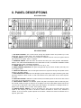
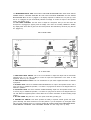
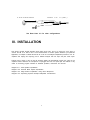
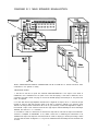
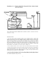
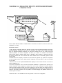
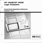
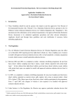
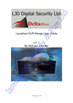
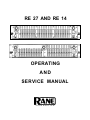
RE 27 AND RE 14
OPERATING
AND
SERVICE MANUAL
C O R P O R A T I O N
1. WARRANTY EXPLANATION — PLEASE READ CAREFULLY
Rane offers a limited warranty, described in full on the Limited Warranty card included in the
packing materials, which covers both parts and labor necessary to repair any defects in the
manufacturing of your Rane product.
The warranty period is two (2) years, starting from either(i) the date of retail purchase, as noted
on either the sales slip from an authorized Rane dealer or on the warranty registration card sent,
in to the factory or, (ii) in the event no proof of purchase date is available, from the date of
manufacture, which is coded on the rear of the chassis.
If you send in the registration card according to the instructions on the card, or retain your sales
slip as proof of purchase, you will receive a full two (2) year warranty period from the date of
purchase, regardless of the date of manufacture. If you do not send in the registration card (“I
forgot.”), or you do not have a sales s1ip from an authorized Rane dealer (“My dog ate it.”), the
warranty period will only extend two (2) years from the date of manufacture.
All registered warranties are tracked by serial number, not by owner. Once your Rane product
is registered, it will be covered the full two years, regardless of any change in ownership.
Should you encounter any problems with your Rane product, be sure to contact either your
local Rane dealer or the Rane factory before taking it anywhere for repairs. We will help you to
identify and locate any specific malfunctions, possibly avoid needless shipment, or instruct
you as to the speediest method for authorized repair.
If you must send your Rane product to the factory or a warranty station for repair, BE SURE TO
INCLUDE THE FOLLOWING INFORMATION:
1. YOUR COMPLETE NAME AND RETURN SHIPPING ADDRESS (P.O.
box numbers are NOT acceptable)
2. THE SERIAL NUMBER OF THE RANE PRODUCT IN FOR REPAIR
3. A COMPLETE DESCRIPTION OF ANY AND ALL PROBLEMS YOU
ARE EXPERIENCING WITH THE PRODUCT.
Never ship the unit in any shipping carton other than the original or a replacement supplied by
Rane. Ship only by a reputable carrier. Be sure to insure the package for the full replacement
value. Rane cannot be held responsible for any damage incurred during shipping.
NOTICE REGARDING DAMAGES
THE RANE LIMITED WARRANTY COVERS ONLY THE COSTS IN LABOR AND MATERIALS TO
REPAIR DEFECTS IN MATERIAL OR WORKMANSHIP OR, AT RANE’S OPTION, TO REPLACE
DEFECTIVE PRODUCTS. CONSEQUENTIAL AND INCIDENTAL DAMAGES SUCH AS ECONOMIC LOSS OR INJURY TO PERSON OR PROPERTY, WHATEVER THE CAUSE, ARE
EXCLUDED FROM COVERAGE. PLEASE REFER TO THE LIMITED WARRANTY CARD FOR A
FULL DESCRIPTION OF THE LIMITS ON THE COVERAGE OF THE LIMITED WARRANTY.
If you need further assistance concerning the repair, installation or operation of your Rane
product, please feel free to contact Rane galactic headquarters at:
Rane Corporation
10802 47th Avenue West
Mukilteo, WA 98275-5098
Phone: (425) 355-6000
FAX: (425) 347-7757
2
II. PANEL DESCRIPTIONS
RE 27 FRONT PANEL
RE 14 FRONT PANEL
1. EQ LEVEL CONTROL: This controls volume through the equalizer section and provides up to 6 dB
overall gain. Turn this control down if the overload LED lights up.
2. BYPASS SWITCH: Push this button IN to bypass the equalizer and level control; the bypass LED will
light whenever the bypass switch is engaged.
3. PINKNOISE SWITCH: Press this button IN toactivate the built-in pink noise generator. IMPORTANT:
SWITCH THE PINK NOISE GENERATOR OFF WHEN NOT IN USE, TO PREVENT POSSIBLE NOISE
BLEEDTHROUGH INTO PROGRAM MATERIAL
4. POWER SWITCH: You’ve probably figured this one out by now...
5. SIGNAL PRESENT INDICATOR: This green LED lights with any input above -20 dBm (.076 volts), even
in the bypass mode.
6. OVERLOAD INDICATOR: This red LED lights whenever the signal level through the equalizer section
reaches 4 dB below clipping
7. ANALYZER DISPLAY LEDs: Each red LED lights up when response is too high in that band; green LEDs
light when response is within ±3 dB or ±1 dB of the selected curve; yellow LEDs come on when response
is too low.
8. EQUALIZER SLIDERS: Calibrated in 3 dB increments, these sliders provide 12 dB of boost and 15 dB of
cut at each of the ISO frequency centers.
9. CURVE SELECT SWITCH: The NORMAL position will yield a flat response when all LEDs are green.
The HOUSE CURVE changes the response of the display such that the EQ sliders between 400 Hz and
1.6 kHz must be attenuated 3 dB to obtain green LED response. This reduction in midrange results in a
warmer more desirable sound at lower sound pressure levels.
10. WINDOW SELECT SWITCH: In the ±3 dB position, the green LED in each band will be lit when
signals of that frequency are within 3 dB above or below the Normal or House curve, whichever is
selected. In the ±1 dB mode, system response must be within 1 dB above or below the selected curve to
light the green LEDs.
3
11. MICROPHONE INPUT JACK: PLUG ONLY THE RANE MICROPHONE INTO THIS JACK--THE DC
POWER SUPPLY VOLTAGE SUPPLIED BY THIS JACK COULD BE DAMAGING TO ANY OTHER
MICROPHONE When the mic is plugged in, the display responds to whatever the mic picks up; when
the mic is unplugged, the jack automatically switches the display to monitor the output of the equalizer
section (see Section IV-9).
12. RTA LEVEL CONTROL: Use this knob to adjust the microphone level (or line level when the
microphone is unplugged) to properly drive the display. This control is accurately calibrated in dB-SPL;
any display band whose LED is green has the sound pressure level indicated by this knob (only with the
mic plugged in).
RE 27 REAR PANEL
RE 14 REAR PANEL
1. PINK NOISE LEVEL ADJUST: Use a 1/8" inch screwdriver to adjust the output from the Pink Noise
generator from 0 to 1.2 volts (-4 dBm) to match the input level requirements of the mixer or other
equipment driven by the generator.
2. PINK NOISE OUTPUT JACK: This is an unbalanced 1/4" jack which supplies Pink Noise to selected
equipment
3. EQ INPUT JACK: This is an automatic balanced/unbalanced 1/4" input to the equalizer section. Use a
mono 1/4" plug for unbalanced operation, or a stereo 1/4" plug wired as shown in the diagram below for
balanced operation.
4. EQ OUTPUT JACK: This is the automatic unbalanced/floating output from the equalizer section. Use
a mono%” plug for unbalanced operation, or a stereo 1/4" plug wired as shown in the diagram below for
use with balanced equipment (Refer to Rane Note 102 for further information on Rane’s floating output
system.)
5. AC LINE CORD: Plug this into a 120 VAC power outlet with grounding pin.
6. GROUND LIFT SWITCH: This switch provides the ability to separate chassis ground and signal
ground. Normally, this switch should be in the LIFT position. If you are tempted to try movingthis switch
with your power amplifiers turned on or turned up, DON’T BE. ALWAYS TURN YOUR AMPLlFIER LEVELS
DOWN BEFORE CHANCING YOUR GROUNDS AROUND and then bring them up slowly.
4
3-PIN
BALANCED
RANE
1/4"
I N
(BAL)
See Rane Note 110 for other configurations.
III. INSTALLATION
This section contains several diagrams which plainly show many, but by no means all, of the ways to
connect the RE 27 or RE 14 into a sound reinforcement or monitor system. Whatever your particular
application, it is helpful to realize that the RE 27 or RE 14 is actuallytwo independent products in one: an
equalizer with input(s) and output(s), and a realtime analyzer with mic input and pink noise output
Another thing to keep in mind is that the analyzer display will automatically monitor the output of the
equalizer section whenever the microphone is unplugged from the front panel jack This feature is very
useful in monitoring program material for feedback problems, resonances and the like.
Diagram III-1 : Main Speaker Equalization
Diagram III-2: Powered Mixer System Equalization
Diagram III-3: Stage Monitor Equalization Using Rane Microphone
Diagram III-4: Equalizing Specific Microphone/Speaker Combinations
5
DIAGRAM III-1: MAIN SPEAKER EQUALIZATION
HEAVY LINES INDICATE DIRECT CONNECTIONS TO RE 27 AND RE 14. Thinner lines show other
connections in the system for clarity.
IMPORTANT NOTES:
1. The RE 27 and RE 14 inputs are automatic balanced/unbalanced. If the output of the mixer is
unbalanced, use a shielded mono 1/4" patch cord to the EQ input(s). If the mixer is balanced, use a
connecting cord with a stereo 1/4" plug on one end for the EQ input(s) and a three-pin or 1/4" jack for the
mixer as required.
2. To drive both left and right amplifier channels from a single RE 27 output, use a “Y” connector to split
the RE 27 output to both left and right inputs of the amp or crossover. (NOTE: If you have the good
fortune to be using a Rane crossover AC 22 or AC 23, you need only connect the single RE 27 output to
the Channel 2 input of the crossover—both left and right outputs will automatically be driven internallyto
eliminate the need for a “Y” connector.)
3. If the RE 27 or RE 14 is more than 10 feet from the amp rack be sure that the input of the electronic
crossover or amplifier is BALANCED. If not, obtain a direct box or balancing line transformer to be
installed at the input of the amp rack. Connect the RE 27 or RE 14 output (s) to the amp rack using a stereo
1/4" plug wired as shown in Diagram I I-1. Long runs of unbalanced lines will usually result in excessive hum
or buzz.
6
DIAGRAM 111-2: POWERED MIXER SYSTEM EQUALIZATION
HEAVY LINES INDICATE DIRECT CONNECTlONS TO THE RE 27 AND RE 14. Thinner lines show other
connections for clarity.
IMPORTANT NOTES:
1. Most powered mixers utilize unbalanced outputs, so use shielded 1/4" mono patch cords (or uncoiled
type guitar cords) for all connections to RE 27 or RE 14.
2. Most powered mixers that contain built-in graphic equalizers provide separate inputs and outputs for
thisequalizer. BE SURE TO INSTALL THE BUILT-IN EQUALIZER AS SHOWN TO BYPASS THE BUILT-IN
EQUALIZER, OTHERWISE THINGS COULD GET RATHER MESSY DUE TO INTERACTION BETWEEN
EQUALIZERS. If the built-in equalizer is NOT bypassable, set all mixer-EQ sliders to the center (0 dB)
position and use only the RE 27 or RE 14 sliders for adjustment
3. You can patch a bypassable built-in equalizer into your monitor system by connecting it between the
Monitor Out and the monitor amp input as shown.
7
DIAGRAM III-3: STAGE MONITOR EQUALIZATION USING RANE
MICROPHONE
HEAVY LINES INDICATE DIRECT CONNECTIONS TO THE RE 27 and RE 14. Thinner lines show other
connections for clarity.
IMPORTANT NOTES:
1. This set-up using the Rane microphone provides the most expedient method to optimize stage
monitor sound quality and also reduce feedback problems. Feedback induced by specific stage
midmonitor speaker coupling can also be attenuated by leaving the stage mic turned up and running up
the pink noise level through the monitor speaker until feedback occurs. Attenuate each feedback
frequency, as indicated by the analyzer display, until the mic/monitor combination feeds back at two or
more frequencies simultaneously. Usually the final EQ setting will be a compromise between a good
monitor sound and a not-so good monitor sound that gets louder before feedback If maximum SPL
before feedback is most important, use the set-up shown in Diagram III-4.
2. The run between the RE 27 or RE 14 and the monitor amp should be balanced whenever possible.
3. Place the Rane microphone at eye level of the performer and about six inches OFF TO ONE SIDE OF
THE STAGE MICROPHONE, in line of sight to the monitor speaker. If the stage microphone is directly
between the Rane mic and monitor speaker (blocking line of sight), some high frequencies will be
blocked giving a false reading on the analyzer display.
4. If you are running more than one monitor from a single equalizer, test each monitor location by
running up pink noise until feedback occurs. The monitor which feeds back soonest should be used for
the overall EQ adjustments using pink noise.
8
DIAGRAM III-4: EQUALIZING SPEClFIC MICROPHONE/SPEAKER
COMBINATIONS
HEAVY LINES INDICATE DIRECT CONNECTIONS TO THE RE 27 and RE 14. Thinner lines show other
connections for clarity.
IMPORTANT NOTES
1. Using this test configuration allows the analyzerto look at the specific relationship between each stage
microphone/speaker combination. Since both the microphone and stage monitor speaker will exhibit
their own individual feedback tendencies, the inter-action between the two can cause pronounced
feedback problems. The above configuration will allow you to flatten or “normalize” this interaction
without actually getting to feedback levels (which is desirable in many situations). It should be noted that
this testing procedure will favor maximum SPL before feedback and not necessarily optimum monitor
sound quality.
2. Dashed lines show temporary connections for pink noise test purposes only; repeat this configuration
for each microphone input channel. When testing is completed, connect the RE 27 or RE 14 as indicated
by solid lines.
3. Mixers that do not have separate SEND/RECEIVE capability for each channel will have to be wired as
shown in Diagram I I l-3.
4. The above configuration can be used for main speaker equalization to optimize system response for a
specific microphone used throughout the system, such as for choir, orchestral or big band situations
where all program material is picked up through microphones of the same make and model Patch the RE
27 or RE 14 (using channel 2 of the RE 14) into a SEND/RECEIVE loop as shown by the dashed lines, but
make the final output connection for the equalizer to the MAIN amp(s) and speakers instead of the
monitor system as shown.
*NOTE: Be sure to use CHANNEL 2 when using the RE 14 in this test configuration.
9
IV. OPERATING METHODS
Since the RE 27 and RE 14 feature a unique form of realtime analyzer, we highly recommend that you
read through this section before performing an alignment with pink noise. If you’ve never used an
analyzer before, use the step-by-step procedure on your first occasion--you’ll be delighted at how simple
it really is. For those more experienced we recommend a quick read-through of the Quickie Summary
section, which contains a few tips that could save you trial and error.
QUICKIE SUMMARY
1. FLAT IS NOT BEAUTIFUL: Equalizers have two basic purposes: to correct and enhance. The Rane
analyzers will allow you to accurately correct system response to each location, a task very difficult to do
by ear. Once this is quickly done, then adjust for further sound quality enhancement by ear; only rarely
will a system be left in a ”flat” response condition.
2. USE MORE THAN ONE TEST MICROPHONE LOCATION: Speaker dispersion characteristics vary
greatly, from beamy highs to boomy bass traps. While performing the pink noise test, try at least two
different test mic locations and average the two if they differ, so that you don’t favor one section of the
listening area.
3. USE ENOUGH PINK NOISE VOLUME TO OVERRIDE BACKGROUND NOISE: There’s no need to run
deafening pink noise levels to EQ a system. Just be sure that no green/red LED respond when pink noise
is turned off (if they do, background noise is causing erroneous readings--pink noise should be turned up
higher).
4. USE ±3 dB DISPLAY SETTING FOR LOW FREQUENCY ADJUSTMENTS: The crest factor (peak
response) of true pink noise causes considerable LED flutter in the ±1 dB mode, making it difficult to
adjust quickly. We recommend that the ±3 dB setting be used on frequencies below 500 Hz or so; use the
±1 dB on the more sensitive mids and highs.
5. THE ANALYZER SECTION CAN BE USED WITH ANY OTHER EQUALIZER: The analyzer section of the
RE 27 and RE 14 will respond to whatever the microphone picks up. Simply run pink noise through the
desired equalizer (channel) and speaker and use the Rane analyzer to adjust that particular EQ.
6. MONITORING PROGRAM WITH ANALYZER DISPLAY: When the front panel microphone is
unplugged, the analyzer display automatically monitors the output of the equalizer section (Channel 2
on the RE 14). Use this feature to identify specific feedback points by watching for red LEDs during the
performance; you can then apply EQ exactly where it’s needed very quickly.
10
STEP BY STEP PROCEDURE
1. SYSTEM HOOK-UP: Connect the RE 27 or RE 14 into your system as shown in Diagrams III-1 through
111-4, whichever is appropriate. Plug the Rane condenser microphone into the front panel jack.
CAUTION: DO NOT PLUG ANY OTHER MICROPHONE INTO THE FRONT PANEL JACK ON THE RE 27
or RE 14: THIS JACK CONTAINS DC POWER SUPPLY VOLTAGE FOR THE RANE CONDENSER
MICROPHONE WHICH MAY BE DAMAGING TO OTHER MICROPHONES.
For special applications you can use another microphone by patching into a Send/Receive loop on a
mixer as described in Rane Note 104 (available on request).
2. BACKGROUND NOISE CHECK: Any background noises such as air conditioners, talking nearby traffic
and the like can cause false readings on the analyzer display if the pink noise volume through the
speakers is not loud enough to drown these noises out. Before turning on the pink noise, turn up the RTA
Level control on the RE 27 or RE 14 until some of the green and red LEDs respond on the display: now
you’re looking at background noise. Slowly turn the RTA Level control back counter-clockwise until all
the green and red LEDs are off, and no background noise is showing on the display. You will now have to
run the pink noise volume through the speakers loud enough to make sure that the RTA Level control is
not turned clockwise (up) from this setting otherwise the background noise will falsify the readings.
3. PINK NOISE RUN-UP: Turn down the mixer output controls before switching on the pink noise, so
that you don’t detonate your speaker cabinets inadvertently. Now switch the pink noise button IN ON
THE RE 27/RE 14 and turn up the mixer and EQ Level controls slowly until you hear pink noise through
the speaker(s). There is a pink noise output level adjustment on the rear of the RE 27 and RE 14—use a 1/8"
screwdriver to increase or decrease the amount of pink noise to the mixer as necessary.
4. MICROPHONE PLACEMENT: You should perform the pink noise test with at least TWO DIFFERENT
TEST MICROPHONE LOCATIONS for each separate channel of EQ. Since speaker dispersion
characteristics can vary greatly, it is desirable to look at a couple of different areas with the test mic to
obtain an average for the entire listening area If you are using one equalizer channel for both speakers
(mono), place the test mic in the center of the left half of the listening area and adjust for green LEDs with
pink noise through the left speaker. Now move the test mic to the center of the right half of the listening
area, run pink noise through the right speaker and observe the analyzer LEDs: use the RTA Level control to
center the response for as many green LEDs lit as possible. For each frequency that requires a different
adjustment than the left channel, note the original setting of the slider, then adjust it so that the green
LED above it is lit and then note this new slider position: the final setting should be half-way between
these two slider positions, resulting in an average response for the left and right channels. If you are
running stereo, use two mic locations for each channel, averaging in the same manner if there are
differences.
NOTE: Wherever possible, try to correct for differences by re-aiming or re-locating speaker cabinets,
using EQ adjustments as a last resort
5. ANALYZER SETTINGS: Select either NORMAL or HOUSE CURVE on the RE 27 or RE 14 display.
Normal is generally used for large concert halls, large theatres and outdoor facilities. Use the HOUSE
CURVE for smaller concert halls, lounges, churches, etc. In this mode the analyzer is modified requiring
that all sliders between 400 Hz and 1.6 kHz must be attenuated -3 dB in order to obtain green LED
response (this is most easily seen in the ±l dB mode). This results in a warmer sound quality at lower
sound pressure levels, requiring less additional adjustment after the pink noise test.
11
Now select either the +3 dB or the ±1 dB Window on the analyzer. We recommend starting with the
+3 dB setting, then switching to the ±1 dB mode for fine-tuning frequencies above 400 or 500 Hz. The
crest factor (peak response) of true pink noise causes considerable LED flutter in the ±1 dB mode below
about 500 Hz, thus it is more expedient to use the ±3 dB setting for these frequencies.
6. INITIAL SYSTEM ALIGNMENT: Before using the equalizer for adjustment, use the analyzer to align
other equipment in the system (EQ should always be a LAST resort after you’ve corrected response
problems everywhere else). With all EQ sliders flat (centered) adjust the electronic crossover
frequencies and level controls (if used), passive crossover controls, speaker placement and alignment,
etc. to get as many green LEDs lit as possible on the display. Only after this is done should you use the
equalizer sliders to flatten the system (see next step).
7. EQUALIZER SLIDER ADJUSTMENTS: Now adjust each slider up or down as necessary until the green
LED above it is lit; if the red is lit, move the slider down until green comes on. If yellow is lit, move the
slider up to obtain green.
If you can’t get one or more green LEDs lit with their sliders fully boosted or cut, make a slight adjustment
in the pink noise volume or RTA Level control to get these bands in the green. Then readjust the
remaining sliders. You will also notice that adjusting one slider may affect the LED readings on the
adjacent bands: this is due to the presence of frequencies half-way between the two bands, which will be
affected by both sliders. Not to worry: simply nudge the adjacent slider until the green LED lights up
again.
8. FINAL EQUALIZER ADJUSTMENTS: Once the RE 27 or RE 14 is all “greened out”, you’re done with the
pink noise alignment test Now the speakers are properly coupled to the specific room and the overall
system response is accurately aligned. This alone will make a great improvement in most systems, but
DON’T STOP AT FLAT necessarily. Now that the RE 27 or RE 14 has given you a consistent starting point,
feel free to make further slider adjustments during the performance or sound check to enhance overall
sound quality: fatten the bass, smoothen the mids or sweeten the highs to taste. You will probably find
that these adjustments will be consistently set above or below the pink noise test settings the same
amount at each performance; make a note of these further adjustments to save future tweeking during
performances. For example, you note the pink noise settings and find later that you like to have 3 dB
more boost at 63 Hz for more low-end punch during the performance. Next time, green out the analyzer
during the pink noise test (get all LEDs green before making any further adjustment), then immediately
bump up the 63 Hz slider 3 dB as indicated by the front panel calibrations so that you’re tuned up before
the show starts (slick, no?). The constant-Q sliders will assure accurate adjustments from any slider
position.
9. USING THE RANE ANALYZER WITH OTHER EQUALIZER CHANNELS: The analyzer section of the RE
27 or RE 14 will respond to whatever program the test microphone picks up. Therefore, the display can
be used to adjust any equalizer channel which controls the pink noise through the speaker(s). For
example, suppose you are running the RE 14 for left and right main speakers. Plug the pink noise output
into the mixer, turn up channel 2 on the RE 14 and turn off channel 1, so that only one speaker emits pink
noise. Use the analyzer to adjust the channel 2 sliders. When completed, turn DOWN channel 2 and turn
up channel 1 on the RE 14: now the other speaker should be emitting pink noise. Use the analyzer to
adjust the channel 1 sliders (don’t forget to re-position the test microphone). This same procedure
applies to any other equalizer in the system: simply run pink noise through the desired equalizer and use
the analyzer/microphone combination to adjust that equalizer.
10. MONITORING PROGRAM MATERIAL FOR FEEDBACK USING THE DISPLAY: Once the pink noise
test is completed, switch off the pink noise on the RE 27 or RE 14 and unplug the Rane test microphone
from the front panel jack. When the mic is unplugged, the display is automatically switched to monitor
the output of the equalizer section (Channel 2 on the RE 14). Adjust the RTA Level control so that an
occasional green LED blinks on during the performance peaks, but no red LEDs come on: you should be in
the ±3 dB mode on the display. If feedback occurs, one or more red LEDs will light showing the general
12
feedback frequency area Usually several red LEDs will be lit by the time you quickly cut backvolume to
kill the feedback and glance at the display. When this happens keep watching the display: the last red
LED to go off contains the exact feedback frequency (it was the first LED on, too, but you probably didn’t
see it). Adjust that slider down a couple dB and feedback problem will be reduced. If you’re real good
you’ll keep one eye on the analyzer display and quickly adjust one or two sliders when feedback occurs,
without altering master volume levels. This program monitoring feature is particularly useful for stage
monitors which are usually plagued with feedback problems.
V. SPECIFICATIONS
All sliders centered and level controls set at unity gain unless otherwise noted
EQUALIZER SECTION
RE 27: (27) 1/3-octave Constant-Q derived filters on IS0 centers from 40 Hz to 16 kHz.
RE 14: (14) 2/3-octave Constant-Q derived filters on IS0 centers from 40 Hz to 16 kHz.
Center Frequency Accuracy;. ±3% maximum.
Filter Type: Constant-Q, state variable derived (no inductors or gyrators).
Sliders: 45 mm full-throw, positive center detent (grounded).
Range: Boost: 12 dB, +2/-l dB; Cut: 15 dB, +2/+1 dB.
Signal/Noise Ratios, re +4dBm, unweighted, 20 kHz bandwidth:
Sliders
Sliders
Sliders
Sliders
centered, unity gain:
centered, max gain:
max. unity gain:
max, max gain:
RE 27
RE 14
92dB
90dB
73dB
69dB
88dB
84dB
69dB
64dB
Frequency Response: 20Hz to 50kHz, +0/-3dB.
THD + Noise: less than .009%, 20-20kHz with +4dBm output.
IM Distortion: less than .02%, 60/7kHz, 4:l.
Maximum Gain: +6dB (+3/-0dB) with sliders centered.
Input Impedance: 20k ohms.
Output Impedance: 100 ohms.
Maximum Input Level:
+22dBm (9.7 VRMS), level control below unity gain.
+19dBm (7.0 VRMS), level control at unity gain.
+14dBm (4.0 VRMS), level control maximum.
Maximum Output Level (600 ohms):
+20dBm (7.8 VRMS), level control max.
+18dBm (6.2 VRMS), level control at unity gain.
13
Subsonic Filter: fixed at 20Hz, 18dB/octave.
Ultrasonic Filter: fixed at 50kHz, 12dB/octave.
Overload Indicator: Red LED, lights at 4dB below clipping.
Signal Present Indicator: Green LED, lights above -20dBm input.
RE 14 Channel Separation: better than 75dB, 20-20kHz.
RFI Input Filters.
Bypass Switch: Passive (hard-wire type), red LED indicated (bypass=on).
Output Relay: Turn on/off transient control.
ANALYZER SECTION
Display Range: +1 dB or ±3dB “green” window, selectable.
Measurement Level Range: 70dB to 120dB SPL, calibrated.
Curve Selection: Normal: flat from 40-16kHz, ±.5dB.
House: +3dB boost between 400 Hz & 1.6kHz.
Display Attack Time: Peak Instantaneous.
Frequency Accuracy: ±5% maximum.
Analyzer Filters: ANSI Class II
Pink Noise: Pseudo-random NMOS digitally-synthesized, 23-bit word length, 1 min. repetition rate.
Output level adjustable to +4dBm. Response: 16Hz to 20kHz, +1 dB; crest factor 4.0.
Microphone: Omnidirectional back-electret condenser type, powered by front panel jack (not
phantom power).
Sensitivity: -65dB.
Frequency Response: 20Hz to 16kHz.
Maximum SPL: 140dB.
MISCELLANEOUS
Chassis and Front Panel: Cold rolled steel.
Size: 19"W x 3.5"H x 8.5" rack depth.
Weight: RE 27: 11 Ib net RE 14: 11l Ib net
14