1
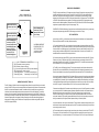
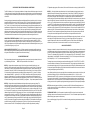
YELLOW WIRE
12V REGULATOR
ADC-16 Analog to Digital Card
7812
(-)
RED WIRE
(+)
POWER
SUPPLY
T R S - - +
WIRE
NUT
BLACK WIRE
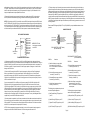
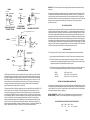
BAUD RATE SELECTION FOR THE ADC-16
Select the desired baud rate by placing the removable shunts in the positions which correspond to the desired baud
rate. All four of the shunts must be in place for the ADC-16 to operate properly.
BAUD RATE
BAUD RATE
50
1800
75
2000
110
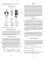
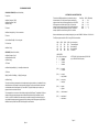
PIN 39 (EPE)
WLS1
WLS2
SBS (PINS 38, 37, 36)
PIN 35 (PI)
0 = Odd Parity
1 = Even parity
0
0
1
1
0
0
1
1
0
0
0
0
1
1
1
1
0
1
0
1
0
1
0
1
0 = Parity On
1 = Parity Off
(5 data bits, 1 stop bit)
(5 data bits, 1.5 stop bits)
(6 data bits, 1 stop bit)
(6 data bits, 2 stop bits)
(7 data bits, 1 stop bit)
(7 data bits, 2 stop bits)
(8 data bits, 1 stop bit)
(8 data bits, 2 stop bits)
NOTE: 1=(+5 VDC), 0=(ground (-))
All pins must be connected to 5 volts or
ground. Do not allow any pins to float
(pins left unconnected).
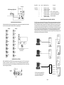
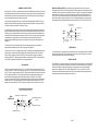
RS-485 INTERFACING AND RS-232 DISTANCE LIMITATIONS
The RS-232 interface will allow the AR-16, ADC-4(8)(16) or STA-8(16) interface cards to be located up to 50 feet from
the computer using a single 3 conductor wire. When distances need to be greater, the RS-422, RS-423 and the RS422A, RS-485 interfaces will allow the Interface card to be located up to 4,000 feet from the computer using a 2 pair
communications cable (4 conductor/2 twisted pairs of wire or CAT5). Shielding of the communication cable/CAT5 is
recommended to protect against electrical storm EMI. The PS-4 or PS-8 port selector may be used to select one port
(1 of 4 or 1 of 8) to control up to 8 interface cards (ADC-16, STA-16 or AR-16) at various locations up to 4,000 feet
from the port selector, providing up to 256 analog inputs, up to 1,152 status inputs and providing control of up to
1,024 relays. A total of up to (16) PS-8 port selectors may be connected to a single RS-232 port, allowing for a total of
4,096 analog inputs, 18,432 status inputs and 16,384 relays.
AR-16, ADC-4
ADC-8, ADC-16,
STA-8 or STA-16
2400
134.5
3600
150
4800
AR-16, ADC-4
ADC-8, ADC-16,
STA-8 or STA-16
RS-232
Interface
50 feet
RS-485 option
AR-16, ADC-4
ADC-8, ADC-16,
STA-8 or STA-16
300
7200
EXAMPLE SHOWS 9,600
BAUD SELECTED
600
9600
1200
19200
AR-16, ADC-4
ADC-8, ADC-16,
STA-8 or STA-16
RS-485
Interface
4,000 feet
RS-485 option
AR-16, ADC-4
ADC-8, ADC-16,
STA-8 or STA-16
CHANGING PROTOCOL SETTINGS
PARITY, WORD LENGTH and STOP BITS: These functions are selected using pins 35, 36, 37, 38 and 39 on the 40
pin UART IC on the ADC-16. Connect the pins to the (+) 5 volt or (-) ground power feed (located above and below
pins 35 thru 39) as shown in the chart on the following page to select the desired protocol. Be sure to cut the existing
circuit track using a knife (if different).
RS-232
Interface
4,000 feet*
50 feet
PS-4 PORT
SELECTOR
(-)
40 PIN UART
4,000 feet*
35
36
37
38
39
Bottom View
(solder side)
40
4,000 feet*
(+)
RS-485 option
AR-16, ADC-4
ADC-8, ADC-16,
STA-8 or STA-16
4,000 feet*
The PS-4 converts the computer RS-232
into (4) software selectable RS-485 ports
(also available in RS-422A/RS-422).
* Two twisted wire pairs
RS-485 option
Page 8
Page 9