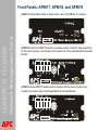
1
Contents
Introduction 1
Product Description . . . . . . . . . . . . . . . . . . . . . . . . . . . . . . . . . . . . . . . . . . 1
Internal Management Features . . . . . . . . . . . . . . . . . . . . . . . . . . . . . . . . . . 4
Network Management Card
USER’S GUIDE
How to Recover from a Lost Password . . . . . . . . . . . . . . . . . . . . . . . . . . . 6
Front Panels: AP9617, AP9618, and AP9619 . . . . . . . . . . . . . . . . . . . . . . 7
Watchdog Features . . . . . . . . . . . . . . . . . . . . . . . . . . . . . . . . . . . . . . . . . . 11
Control Console 13
How To Log On . . . . . . . . . . . . . . . . . . . . . . . . . . . . . . . . . . . . . . . . . . . . . 13
Main Screen . . . . . . . . . . . . . . . . . . . . . . . . . . . . . . . . . . . . . . . . . . . . . . . . 16
Control Console Menus . . . . . . . . . . . . . . . . . . . . . . . . . . . . . . . . . . . . . . 19
Web Interface 22
Introduction . . . . . . . . . . . . . . . . . . . . . . . . . . . . . . . . . . . . . . . . . . . . . . . . 22
How to Log On . . . . . . . . . . . . . . . . . . . . . . . . . . . . . . . . . . . . . . . . . . . . . . 23
Home Page . . . . . . . . . . . . . . . . . . . . . . . . . . . . . . . . . . . . . . . . . . . . . . . . . 25
How to Use the Tabs, Menus, and Links . . . . . . . . . . . . . . . . . . . . . . . . . 26
Monitor and Configure the UPS 28
Overview Page . . . . . . . . . . . . . . . . . . . . . . . . . . . . . . . . . . . . . . . . . . . . . . 28
Status Option . . . . . . . . . . . . . . . . . . . . . . . . . . . . . . . . . . . . . . . . . . . . . . . 29
Control Options . . . . . . . . . . . . . . . . . . . . . . . . . . . . . . . . . . . . . . . . . . . . . 30
Configuration Options. . . . . . . . . . . . . . . . . . . . . . . . . . . . . . . . . . . . . . . . 36
Diagnostics . . . . . . . . . . . . . . . . . . . . . . . . . . . . . . . . . . . . . . . . . . . . . . . . 39
Outlet Groups (Smart-UPS XLM) . . . . . . . . . . . . . . . . . . . . . . . . . . . . . . . 40
The Scheduling Option (for Shutdowns) . . . . . . . . . . . . . . . . . . . . . . . . . 43
The Sync Control Option . . . . . . . . . . . . . . . . . . . . . . . . . . . . . . . . . . . . . 44
The PowerChute Option . . . . . . . . . . . . . . . . . . . . . . . . . . . . . . . . . . . . . . 46
The About Option . . . . . . . . . . . . . . . . . . . . . . . . . . . . . . . . . . . . . . . . . . . 48
®
i
Environmental Monitoring 49
Overview Page . . . . . . . . . . . . . . . . . . . . . . . . . . . . . . . . . . . . . . . . . . . . . . 49
Temperature and Humidity Option . . . . . . . . . . . . . . . . . . . . . . . . . . . . . 50
Input Contacts Option. . . . . . . . . . . . . . . . . . . . . . . . . . . . . . . . . . . . . . . . 52
Output Relay Option . . . . . . . . . . . . . . . . . . . . . . . . . . . . . . . . . . . . . . . . . 53
About . . . . . . . . . . . . . . . . . . . . . . . . . . . . . . . . . . . . . . . . . . . . . . . . . . . . . 53
Administration: Security 54
Network Management Card
USER’S GUIDE
Local Users . . . . . . . . . . . . . . . . . . . . . . . . . . . . . . . . . . . . . . . . . . . . . . . . 54
Remote Users . . . . . . . . . . . . . . . . . . . . . . . . . . . . . . . . . . . . . . . . . . . . . . 54
Configuring the RADIUS Server. . . . . . . . . . . . . . . . . . . . . . . . . . . . . . . . 56
Inactivity Timeout (Administration>Security>Auto Log Off). . . . . . . . . 58
Administration: Network Features 59
TCP/IP and Communication Settings . . . . . . . . . . . . . . . . . . . . . . . . . . . 59
DNS (Administration>Network>DNS>options) . . . . . . . . . . . . . . . . . . . . 64
Web (Administration>Network>Web>options) . . . . . . . . . . . . . . . . . . . . 66
Console (Administration>Network>Console>options) . . . . . . . . . . . . . 68
SNMP . . . . . . . . . . . . . . . . . . . . . . . . . . . . . . . . . . . . . . . . . . . . . . . . . . . . . 70
FTP Server (Administration>Network>FTP Server) . . . . . . . . . . . . . . . . 73
WAP (for Smart-UPS models only) . . . . . . . . . . . . . . . . . . . . . . . . . . . . . 74
Administration: Notification and Logging 75
Event Actions (Administration>Notification>Event Actions>options). 75
Active, Automatic, Direct Notification . . . . . . . . . . . . . . . . . . . . . . . . . . . 77
Indirect Notification through Logs or Queries . . . . . . . . . . . . . . . . . . . . 95
Administration: General Options 100
Identification (Administration>General>Identification) . . . . . . . . . . . . 100
Set the Date and Time . . . . . . . . . . . . . . . . . . . . . . . . . . . . . . . . . . . . . . . 100
Use an .ini File (Administration>General>User Config File) . . . . . . . . 102
Temperature Units (Administration>General>Unit Preference) . . . . . 102
Reset the Interface (Administration>General>Reset/Reboot). . . . . . . 102
Configuring Links (Administration>General>Quick Links) . . . . . . . . . 103
®
ii
About the Management Card (Administration>General>About). . . . . 104
APC Device IP Configuration Wizard 105
Capabilities, Requirements, and Installation . . . . . . . . . . . . . . . . . . . . 105
Use the Wizard. . . . . . . . . . . . . . . . . . . . . . . . . . . . . . . . . . . . . . . . . . . . . 106
How to Export Configuration Settings 108
Retrieving and Exporting the .ini File . . . . . . . . . . . . . . . . . . . . . . . . . . 108
The Upload Event and Error Messages. . . . . . . . . . . . . . . . . . . . . . . . . 111
Network Management Card
USER’S GUIDE
Related Topics . . . . . . . . . . . . . . . . . . . . . . . . . . . . . . . . . . . . . . . . . . . . . 112
File Transfers 113
Upgrading Firmware . . . . . . . . . . . . . . . . . . . . . . . . . . . . . . . . . . . . . . . . 113
Firmware File Transfer Methods . . . . . . . . . . . . . . . . . . . . . . . . . . . . . . 114
Verifying Upgrades and Updates . . . . . . . . . . . . . . . . . . . . . . . . . . . . . . 118
Troubleshooting 119
Management Card Access Problems . . . . . . . . . . . . . . . . . . . . . . . . . . 119
SNMP Issues . . . . . . . . . . . . . . . . . . . . . . . . . . . . . . . . . . . . . . . . . . . . . . 121
Synchronization Problems . . . . . . . . . . . . . . . . . . . . . . . . . . . . . . . . . . . 122
Product Information 123
Two-Year Factory Warranty . . . . . . . . . . . . . . . . . . . . . . . . . . . . . . . . . . 123
Life-Support Policy . . . . . . . . . . . . . . . . . . . . . . . . . . . . . . . . . . . . . . . . . 126
Index 127
®
iii
Introduction
Product Description
Network Management Card
USER’S GUIDE
Features
The following APC Network Management Cards and devices are Web-based products
that manage supported devices using multiple, open standards such as Hypertext
Transfer Protocol (HTTP), Telnet, Hypertext Transfer Protocol over Secure Sockets
Layer (HTTPS), Simple Network Management Protocol (SNMP), File Transfer Protocol
(FTP), and Secure CoPy (SCP):
• The AP9617 Network Management Card EX:
– Provides the ability to export a user configuration (.ini) file from a configured card to
one or more unconfigured cards without converting the file to a binary file
– Supports using a Dynamic Host Configuration Protocol (DHCP) or server to
provide the Management Card’s network (TCP/IP) values
– Supports using the APC Remote Monitoring Service (RMS)
– Provides data and event logs
– Provides UPS shutdown and self-test scheduling features
– Provides support for the APC PowerChute® Network Shutdown utility
– Enables you to configure notification through event logging (by the Management
Card and Syslog), e-mail, and SNMP traps. You can configure notification for single
events or groups of events, based on the severity level or category of events
– Provides a selection of security protocols for authentication and encryption
• The AP9618 Network Management Card EM/MDM includes all AP9617 features and
the following:
– An Integrated Environmental Monitor that has a temperature sensor, input
contacts, and an output relay
– An internal analog modem
®
1
– A paging feature that lets you configure any event to generate a page to one or
more configured analog or digital pagers when the event occurs. This feature
includes call-back capabilities. Optionally, you can convert Network Management
Card, UPS, and environmental monitoring event codes to the default Out-of-Band
Management Card event codes (supplemented by several additional numeric
codes).
Network Management Card
USER’S GUIDE
• The AP9619 Network Management Card EM includes all AP9617 features and has
an Integrated Environmental Monitor with a temperature sensor, input contacts, and
an output relay.
• In addition to support for the UPS Network Management Cards, the Network
Management Card firmware supports the network-enabled model of the APC S Type
Power Conditioner with Battery Backup, which provides surge protection, isolated
noise filtering, and voltage regulation, in addition to battery backup, for high
performance audio-visual (AV), home security, and automation systems.
Upgrade kits available from APC. Use the AP9618U kit to upgrade AP9617 to
include the features of AP9618 or to upgrade AP9619 to include the AP9618 analog
modem. Use the AP9619U kit to upgrade AP9617 to include the features of AP9619.
For an AP9618 Network Management Card EM/MDM or AP9619 Network
Management Card EM you can also purchase a humidity sensor from APC.
APC devices in which you can install the Management Card. The Management
Card can be installed into the following APC devices:
• Any Smart-UPS® or Matrix-UPS® model that has an internal expansion slot, or any
Silcon™, AIS 5000, Symmetra®, or Symmetra PX UPS. (The APC S Type Power
Conditioner with Battery Backup, S20BLK, has an embedded Management Card.)
• Triple Chassis Protocol Converter (AP9604S), required for a Silcon UPS, which does
not have an expansion slot.
• Expansion Chassis (AP9600).
• Triple Expansion Chassis (AP9604).
®
2
Initial setup
You must define three TCP/IP settings for the Network Management Card before it can
operate on the network:
Network Management Card
USER’S GUIDE
• IP address of the Management Card
• Subnet mask
• IP address of the default gateway
Do not use the loopback address (127.0.0.1) as the default gateway. Doing so disables
the card. You must then log on using a serial connection and reset TCP/IP settings to
their defaults.
To configure the TCP/IP settings, see the Network Management Card
Installation and Quick Start Manual, available on the APC Network
Management Card Utility CD and in printed form.
For detailed information on how to use a DHCP server to configure the TCP/
IP settings at a Management Card, see TCP/IP and Communication Settings.
Network management features
These applications and utilities work with a UPS that connects to the network through a
Network Management Card.
• PowerChute® Network Shutdown to provide unattended remote graceful shutdown of
computers that are connected to APC UPSs
• APC InfraStruXure™ Manager for enterprise-level power management and
management of APC agents, UPSs, information controllers, and environmental
monitors
• PowerChute Business Edition to provide department-level safe system shutdown and
UPS management for workstations and servers
• APC PowerNet® Management Information Base (MIB) with a standard MIB browser
to perform SNMP SETs and GETs and to use SNMP traps
• The APC Device IP Configuration Wizard to configure the basic settings of one or
more Network Management Cards over the network
®
3
• The APC Security Wizard to create components needed for high security for the
Network Management Card when you are using Secure Sockets Layer (SSL) and
related protocols and encryption routines
Internal Management Features
Network Management Card
USER’S GUIDE
Overview
Use the Web interface or the control console interface to manage the UPS, an
environmental monitor (the Integrated Environmental Monitor at an AP9618 or AP9619
Management Card, an external environmental monitor, or the sensor of and APC S
Type Power Conditioner with Battery Backup), and the Management Card itself.
For more information about the internal user interfaces, see Web Interface
and Control Console.
Access priority for logging on
Only one user at a time can log on to the Management Card. The priority for access,
beginning with the highest priority, is as follows:
• Local access to the control console from a computer with a direct serial connection to
the Management Card.
• Telnet or Secure SHell (SSH) access to the control console from a remote computer.
• Web access, either directly or through the InfraStruXure Manager.
See SNMP for information about how SNMP access to the Management
Card is controlled.
®
4
Types of user accounts
The Management Card has three levels of access (Administrator, Device User, and
Read-Only User), which are protected by user name and password requirements.
• An Administrator can use all the menus in the Web interface and control console. The
default user name and password are both apc.
Network Management Card
USER’S GUIDE
• A Device User can access only the following:
– In the Web interface, the menus on the UPS and Environment tabs and the event
and data logs, accessible under the Events and Data headings on the left
navigation menu of the Logs tab.
– In the control console, the equivalent features and options.
The default user name is device, and the default password is apc.
• A Read-Only User has the following restricted access:
– Access through the Web interface only.
– Access to the same tabs and menus as a Device User, but without the capability to
change configurations, control devices, delete data, or use file transfer options.
Links to configuration options are visible but disabled, and the event and data logs
display no button to clear the log.
The default user name is readonly, and the default password is apc.
To set User Name and Password values for the three account types, see
Setting user access (Administration>Security>Local Users>options).
You must use the Web interface to configure values for the Read-Only User.
®
5
How to Recover from a Lost Password
You can use a local computer, a computer that connects to the Management Card or
other device through the serial port, to access the control console.
Network Management Card
USER’S GUIDE
1. At the local computer, select a serial port, and disable any service that uses it.
2. Connect the serial cable from the selected port on the computer to the
configuration port at the UPS Network Management Card or at the APC S Type
Power Conditioner with Battery Backup:
• For an APC UPS, use the provided serial cable (APC part number 940-0024) or
the longer serial cable that you can order (APC part number 940-1524).
• For an APC S Type Power Conditioner with Battery Backup, use the provided
industry-standard RS-232 serial cable (APC part number 940-1000B.)
3. Run a terminal program (such as HyperTerminal®) and configure the selected
port for 2400 bps, 8 data bits, no parity, 1 stop bit, and no flow control.
4. Press ENTER, repeatedly if necessary, to display the User Name prompt. If you
are unable to display the User Name prompt, verify the following:
5.
6.
7.
8.
9.
• The serial port is not in use by another application.
• The terminal settings are correct as specified in step 3.
• The correct cable is being used as specified in step 2.
Press the Reset button. The Status LED will flash alternately orange and green.
Press the Reset button a second time immediately while the LED is flashing to
reset the user name and password to their defaults temporarily.
Press ENTER as many times as necessary to redisplay the User Name prompt,
then use the default, apc, for the user name and password. (If you take longer
than 30 seconds to log on after the User Name prompt is redisplayed, you must
repeat step 5 and log on again.)
From the Control Console menu, select System, then User Manager.
Select Administrator, and change the User Name and Password settings,
both of which are now defined as apc.
Press CTRL+C, log off, reconnect any serial cable you disconnected, and restart
any service you disabled.
®
6
Front Panels: AP9617, AP9618, and AP9619
Network Management Card
USER’S GUIDE
AP9617 includes Status LEDs, a Reset button, and a 10/100Base-T connector.
AP9618 includes the AP9617 features, an analog modem connector, and connections
for the sensor (probe), input contacts, and output relay of the Integrated Environmental
Monitor.
AP9619 includes AP9617 features and connections for the sensor (probe), input
contacts, and output relay of the Integrated Environmental Monitor.
®
7
Network Management Card
USER’S GUIDE
Features
AP9618 or AP9619
Description
9-pin connector1
• Output relay (Output): Normally closed (NC), common (COM),
and normally open (NO) pins. These pins are used by the
Integrated Environmental Monitor to interface to attached alarm
systems, annunciators (such as lights, beacons, bells, and
buzzers), controllers, HVAC thermostat lines, and similar
devices. They are rated for a switching capacity of 1A 30V AC/
DC.
• Power (Pwr): Normally-open ground (GND NO) and +12VDC
pins can provide up to 25mA of power to devices such as smoke
and motion sensors.
• Input contacts (Zone 1 and 2): Two dry contact inputs. Each
zone can be connected to normally open (NO) contacts, normally
closed (NC) contacts or a combination (COM) of the two. See
Sensor Zone Connections (AP9618 and AP9619 only) for details
Possible applications include magnetic contact switches; tamper
switches; and water, pressure, and smoke sensors.
Probe connector1
Connects a temperature/humidity sensor (probe) to the Integrated
Environmental Monitor.
AP9618 only
Description
Modem connector2
Connects the internal analog modem to an analog phone line to
provide for out-of-band communications.
AP9617, AP9618, AP9619
Description
Reset button
Resets the Management Card while power remains on.
10/100 Base-T connector
Connects the Management Card to the Ethernet network.
Status LEDs
See Status LED.
Link-RX/TX (10/100) LED
See Link-RX/TX (10/100) LED.
1. To manage the Integrated Environmental Monitor, see Environmental Monitoring.
2. To configure this feature for dial-in access to the control console at an AP9618 Network Management
Card, see Dial-in access (AP9618 Management Card only).
®
8
Sensor Zone Connections (AP9618 and AP9619 only)
Network Management Card
USER’S GUIDE
The Network Management Card supports normally open and normally closed loop
systems, and allows mixing of normally open and normally closed sensors on any
zone. Do not cross-connect the sensors of the Management Card with sensors from
any other system.
To use more than one sensor on a zone, connect normally open sensors in parallel and
normally closed sensors in series. To avoid receiving alarms on unused zones, install a
jumper wire between the COM and NC connectors for each unused zone.
®
9
Status LED
Network Management Card
USER’S GUIDE
This LED indicates the Management Card’s status.
Condition
Description
Off
One of the following situations exists:
• The Management Card is not receiving input power.
• The Management Card is starting up.
• The Management Card is not operating properly. It may need to be
repaired or replaced. Contact APC Worldwide Customer Support.
Solid Green
The Management Card has valid TCP/IP settings.
Solid Orange
A hardware failure has been detected in the Management Card. Contact
APC Worldwide Customer Support.
Flashing Green
The Management Card does not have valid TCP/IP settings.1
Flashing Orange
The Management Card is making BOOTP requests.1
Alternately
flashing Green
and Orange
If the LED is alternately flashing slowly, the Management Card is making
DHCP2 requests.1
If the LED is alternately flashing rapidly, the Management Card is starting
up.
1. If you do not use a BOOTP or DHCP server, see the Network Management Card Installation and
Quick Start Manual provided in printed format and on the APC Network Management Card Utility CD
in PDF to configure the TCP/IP settings of the Management Card.
2. To use a DHCP server, see TCP/IP and Communication Settings.
®
10
Link-RX/TX (10/100) LED
Network Management Card
USER’S GUIDE
This LED indicates the network status.
Condition
Description
Off
One or more of the following situations exist:
• The Management Card is not receiving input power.
• The cable that connects the Management Card to the network is
disconnected or defective.
• The device that connects the Management Card to the network is turned
off or not operating correctly.
• The Management Card itself is not operating properly. It may need to be
repaired or replaced. Contact APC Worldwide Customer Support.
Solid Green
The Management Card is connected to a network operating at 10 Megabits
per second (Mbps).
Solid Orange
The Management Card is connected to a network operating at 100
Megabits per second (Mbps).
Flashing Green
The Management Card is receiving or transmitting data packets at 10
Megabits per second (Mbps).
Flashing Orange
The Management Card is receiving or transmitting data packets at 100
Megabits per second (Mbps).
Using the 5-Port 10Base-T Hub SmartSlot Card eliminates the requirement
for a separate hub power supply. However, this card requires that all Network
Management Cards connected to it operate at 10 Mbps, not 100 Mbps.
Watchdog Features
Overview
To detect internal problems and recover from unanticipated inputs, the Management
Card uses internal, system-wide watchdog mechanisms. When it restarts to recover
from an internal problem, a System: Warmstart event is recorded in the event log.
®
11
Network interface watchdog mechanism
The Management Card implements internal watchdog mechanisms to protect itself
from becoming inaccessible over the network. For example, if the Management Card
does not receive any network traffic for 9.5 minutes (either direct traffic, such as SNMP,
or broadcast traffic, such as an Address Resolution Protocol [ARP] request), it
assumes that there is a problem with its network interface and restarts.
Network Management Card
USER’S GUIDE
Resetting the network timer
To ensure that the Management Card does not restart if the network is quiet for 9.5
minutes, the Management Card attempts to contact the default gateway every 4.5
minutes. If the gateway is present, it responds to the Management Card, and that
response restarts the 9.5-minute timer. If your application does not require or have a
gateway, specify the IP address of a computer that is running on the network most of
the time and is on the same subnet. The network traffic of that computer will restart the
9.5-minute timer frequently enough to prevent the Management Card from restarting.
®
12
Control Console
How To Log On
Network Management Card
USER’S GUIDE
Overview
You can use either a local (serial) connection, or a remote (Telnet or SSH) connection
with a computer on the same network (LAN) as the Management Card to access the
control console. For an AP9618 Network Management Card, you can also use its
internal analog modem to access the control console.
See Dial-in access (AP9618 Management Card only).
Use case-sensitive user name and password entries to log on (by default, apc and apc
for an Administrator, or device and apc for a Device User). A Read-Only User has no
access to the control console.
If you cannot remember your user name or password, see How to Recover
from a Lost Password.
Remote access to the control console
You can access the control console through Telnet or Secure SHell (SSH). Telnet is
enabled by default. Enabling SSH disables Telnet.
To enable or disable these access methods:
• In the Web interface, on the Administration tab, select Network on the top menu
bar, and then the access option under Console on the left navigation menu.
• In the control console, use the Telnet/SSH option of the Network menu.
Telnet for basic access. Telnet provides the basic security of authentication by user
name and password, but not the high-security benefits of encryption.
®
13
To use Telnet to access the control console:
Network Management Card
USER’S GUIDE
1. From a computer on the same network as the Management Card, at a
command prompt, type telnet and the System IP address for the
Management Card (for example, telnet 139.225.6.133, when the
Management Card uses the default Telnet port of 23), and press ENTER.
If the Management Card uses a non-default port number (from 5000 to 32768), you
must include a colon or a space, depending on your Telnet client, between the IP
address (or DNS name) and the port number.
2. Enter the user name and password (by default, apc and apc for an
Administrator, or device and apc for a Device User).
SSH for high-security access. If you use the high security of SSL for the Web
interface, use Secure SHell (SSH) for access to the control console. SSH encrypts user
names, passwords and transmitted data. The interface, user accounts, and user
access rights are the same whether you access the control console through SSH or
Telnet, but to use SSH, you must first configure SSH and have an SSH client program
installed on your computer.
Local access to the control console
For local access, use a computer that connects to the Management Card or other
device through the serial port, to access the control console:
1. Select a serial port at the computer and disable any service that uses the port.
2. Connect the serial cable from the selected port on the computer to the
configuration port at the UPS Network Management Card or Expansion
Chassis or at the APC S Type Power Conditioner with Battery Backup:
• For an APC UPS, use the serial cable, APC part number 940-0024 or 940-1524.
• For an APC S Type Power Conditioner with Battery Backup, use the provided
industry-standard RS-232 serial cable, APC part number 940-1000B.
3. Run a terminal program (e.g., HyperTerminal), and configure the selected port
for 2400 bps, 8 data bits, no parity, 1 stop bit, and no flow control.
4. Press ENTER, and at the prompts, enter your user name and password.
®
14
Dial-in access (AP9618 Management Card only)
Network Management Card
USER’S GUIDE
When you have access to the control console locally or remotely, use this option of the
System menu to configure dial-in access to the control console using the Management
Card’s internal analog modem.
Setting
Definition
Console
Dial-In
Enables (by default) or disables dial-in access to the control console through the
analog modem.
Initialization
The initialization string used to ensure proper operation of the modem and
consistent communication between the modem and the Management Card. This
string is sent to the internal modem every time the Management Card restarts, or
when a setting is changed and accepted.
Country
Code
Identifies the country in which the modem is used to match the modem’s
operation to that country’s telephone-system standards.
Terminal
Interface
Enables you to send commands directly to the modem and view the modem’s
response, using a serial, terminal-interface session at a baud rate of 38400.
When you use CTRL+A to end the session, the modem is reset to use the
Initialization setting.
Dialback
With dial-back enabled, when the user whose telephone number is configured as
Dialback String dials in remotely, the Management Card terminates the call
immediately and calls that user’s modem back.
• Dial-back ensures that a dial-in control console session can occur only from the
phone number configured as Dialback String.
• The cost of the control console session is charged to your company or agency
at its telephone calling rate and not to the user who dialed in remotely.
Dialback
String
The modem phone number to call back when Dialback is enabled. Include any
modem commands needed for tasks such as timing, waiting for a dial tone, or
accessing an external telephone line. The default is the sample dial string
9,5551234.
®
15
Main Screen
Sample main screen
Network Management Card
USER’S GUIDE
Following is an example of the screen displayed when you log on to the control console
at an AP9618 or AP9619 Management Card that has the output relay of the Integrated
Environmental Monitor enabled. The Relay OK entry in the environmental status line
indicates that the output relay is enabled and that no alarm condition exists.
American Power Conversion
Network Management Card AOS vx.x.x
(c)Copyright 2005 All Rights Reserved Smart-UPS & Matrix-UPS APP
vx.x.x
-------------------------------------------------------------------------Name
: Test Lab
Date : 11/30/2006
Contact : Don Adams
Time : 5:58:30
Location : Building 3
User : Administrator
Up Time : 0 Days, 21 Hours, 21 Minutes
Stat : P+ N+ A+
Thresholds OK, Contact Alarms OK, Relays OK
Model Name named Tester 8 : On Line
------- Control Console -------------------------------------------------1- Device Manager
2- Network
3- System
4- Logout
<ESC>- Main Menu, <ENTER>- Refresh, <CTRL-L>- Event Log
>
®
16
Information and status fields
Main screen information fields.
Network Management Card
USER’S GUIDE
• Two fields identify the APC operating system (AOS) and application (APP) firmware
versions. The application firmware name identifies the type of UPS that connects to
the network through this Management Card. In the preceding example, the
Management Card uses the application firmware for a UPS in the Smart-UPS/
Matrix-UPS family.
Network Management Card AOS
Smart UPS & Matrix UPS APP
vx.x.x
vx.x.x
• Three fields identify the system name, contact person, and location of the UPS. (In
the control console, use the System menu to set these values.)
Name
Contact
Location
: Test Lab
: Don Adams
: Building 3
• The Up Time field reports how long the Management Card has been running since it
was last turned on or reset.
Up Time
: 0 Days 21 Hours 21 Minutes
• Two fields report when you logged in, by date and time.
Date : 11/30/2006
Time : 5:58:30
• The User field reports whether you logged in through the Administrator or Device
User account. (The Read Only User account cannot access the Control Console.)
User : Administrator
®
17
Main screen status fields.
• The Stat field reports the Management Card status.
Network Management Card
USER’S GUIDE
Stat : P+ N+ A+
P+
The APC operating system (AOS) is functioning properly.
N+
The network is functioning properly.
N?
A BOOTP request cycle is in progress.
N–
The Management Card failed to connect to the network.
N!
Another device is using the Management Card’s IP address.
A+
The application is functioning properly.
A–
The application has a bad checksum.
A?
The application is initializing.
A!
The application is not compatible with the AOS.
If P+ is not displayed, contact APC support staff. See APC Worldwide
Customer Support.
• The field that identifies the UPS model and name also reports the operating status of
the UPS.
Model Name named Tester 8 : On Line
• The environmental field reports the status of the sensors (Thresholds) and contacts
(Contact Alarms) at any environmental monitor, including the output relay (Relay) of
the Integrated Environmental Monitor at an AP9618 or AP9619 Management Card.
Thresholds Ok, Contact Alarms Ok, Relay OK
For more information about the status of the sensor, contact, and output
relay, see Environmental Monitoring.
®
18
Control Console Menus
Overview
The control console provides options to monitor and configure a Management Card, its
UPS, and other supported devices. If a device is not present, the control console
displays no options for that device. For example:
Network Management Card
USER’S GUIDE
• The control console at a Management Card that connects only with an environmental
monitor does not provide UPS options.
• The control console of an AP9617 Network Management Card does not provide
options for an Integrated Environmental Monitor.
How to use control console menus
The menus in the control console list options by number and name. To use an option,
type the option’s number, press ENTER, and follow any on-screen instructions. If you
use an option that changes a setting or value, select Accept Changes to save your
change before you exit the menu.
While using a menu, you can also do the following:
•
•
•
•
•
•
Type ? and press ENTER for menu option descriptions if help exists for the menu.
Press ENTER to refresh the menu
Press ESC to go back to the menu from which you accessed the current menu
Press CTRL+C to return to the main (Control Console) menu
Press CTRL+D to toggle between the UPS and Environment menus
Press CTRL+L to access the event log
Control console structure
For menus not specific to UPSs but shared among APC network-enabled devices,
names and locations of options differ from those of the Web interface. The menu
structure in the control console is retained from earlier firmware versions for
compatibility with scripts and programs that rely on that structure.
®
19
Main menu
Use the main Control Console menu to access the control console’s management
features:
Network Management Card
USER’S GUIDE
1234-
®
Device Manager
Network
System
Logout
When you log on as Device Manager (equivalent to Device User in the Web
interface), you can access only the Device Manager menus and the Logout
menu.
Device Manager menu
Use the options of the Device Manager menu to select the device to manage:
1- UPS Model Name for a UPS, or S20 AV UPS for an S Type Power Conditioner
2- Environment
The UPS option, named with the model name, enables an administrator or device user
to issue UPS control commands, perform diagnostic tests, configure Management
Card and UPS parameters, display detailed UPS status, and view information about
the UPS. A read-only user cannot change settings or parameter values.
The Environment option is displayed if an environmental monitor is present:
• For an AP9618 or AP9619 Network Management Card, this option enables an
administrator or device user to configure the Integrated Environmental Monitor and
any connected external environmental monitor.
• For an APC S Type Power Conditioner with Battery Backup, this option enables an
administrator or device user to configure the device’s sensor:
Network menu
To perform these tasks, use the options of the Network menu:
• Configure the TCP/IP settings of the Management Card or, if the Management Card
obtains its TCP/IP settings from a server, configure the settings for the type of server
(DHCP or BOOTP).
20
• Use the Ping utility.
• Define settings that affect FTP, Telnet, the Web interface and SSL, SNMP, e-mail,
DNS, Syslog, and WAP (Wireless Application Protocol).
• Configure paging parameters for analog or Telolocator Alphanumeric Protocol (TAP)
paging.
System menu
Network Management Card
USER’S GUIDE
To perform these tasks, use the options of the System menu:
• Control Administrator and Device Manager access. (You can control Read Only
User access by using the Web interface only.)
• Define the Name, Contact, and Location values for the system.
• Set the date and time used by the Management Card.
• Through the Tools option:
– Restart the Management Card interface.
– Reset parameters to their default values.
– Delete SSH host keys and SSL certificates.
– Upload an initialization file (.ini file) that has been downloaded from another
Management Card. The current Management Card then uses the values in that .ini
file to configure its own settings.
• Configure modem parameters, including dial-in access to the control console at an
AP9618 Network Management Card using that Management Card’s internal analog
modem.
• Access system information about the Management Card.
®
21
Web Interface
Introduction
Network Management Card
USER’S GUIDE
Overview
The Web interface provides options to manage a Management Card, its UPS, and
other supported devices. If a device is not present, the interface displays no options for
that device. For example:
• The Web interface at a Management Card that connects only with an environmental
monitor does not provide UPS options.
• The Web interface of an AP9617 Network Management Card does not provide
options for an Integrated Environmental Monitor.
See Web (Administration>Network>Web>options) for information on how to
select, enable, and disable the protocols that control access to the Web
interface and to define the Web-server ports for the protocols.
Supported Web browsers
You can use Microsoft® Internet Explorer (IE) 5.5 and higher (on Windows operating
systems only), Firefox, version 1.x, by Mozilla Corporation (on all operating systems),
or Netscape® 7.x and higher (on all operating systems) to access the Management
Card through its Web interface. Other commonly available browsers may work but have
not been fully tested by APC.
The Management Card cannot work with a proxy server. Therefore, before you can use
a Web browser to access its Web interface, you must do one of the following:
• Configure the Web browser to disable the use of a proxy server for the Management
Card.
• Configure the proxy server so that it does not proxy the specific IP address of the
Management Card.
®
22
How to Log On
Overview
You can use a Management Card’s DNS name or System IP address for the URL
address of the Web interface. Use your case-sensitive user name and password to log
on. The default user name differs by account type:
• apc for an Administrator
Network Management Card
USER’S GUIDE
• device for a Device User
• readonly for a Read-Only User
The default password is apc for all three account types.
If you are using HTTPS (SSL/TSL) as your access protocol, your login
credentials are compared with information in a server certificate. If the
certificate was created with the APC Security Wizard, and an IP address was
specified as the common name in the certificate, you must use an IP address
to log on to the Management Card. If a DNS name was specified as the
common name on the certificate, you must use a DNS name to log on.
For information about the Web page displayed when you log on, see Home
Page.
®
23
URL address formats
Type the Management Card’s DNS name or IP address in the Web browser’s URL
address field and press ENTER. When you specify a non-default Web server port in
Internet Explorer, you must include http:// or https:// in the URL.
Network Management Card
USER’S GUIDE
Common browser error messages at log-on.
Cause of the
Error
Browser
Error Message
Someone else
is logged on.
Internet Explorer,
Netscape, Firefox
“You are not authorized to view this page” or “Someone
is currently logged in...”
Web access is
disabled, or the
URL was not
correct
Netscape
“The connection was refused....”
Internet Explorer
“This page cannot be displayed.”
Firefox
“Unable to connect.”
URL format examples.
• For a DNS name of Web1:
– http://Web1 if HTTP is your access mode
– https://Web1 if HTTPS (HTTP with SSL) is your access mode
• For a System IP address of 139.225.6.133 and the default Web server port (80):
– http://139.225.6.133 if HTTP is your access mode
– https://139.225.6.133 if HTTPS (HTTP with SSL) is your access mode
• For a System IP address of 139.225.6.133 and a non-default Web server port (5000):
– http://139.225.6.133:5000 if HTTP is your access mode
– https://139.225.6.133:5000 if HTTPS (HTTP with SSL) is your access
mode.
®
24
Home Page
Overview
On the Home page of the interface, displayed when you log on, you can view active
alarm conditions and the most recent events recorded in the event log.
Network Management Card
USER’S GUIDE
Quick status icons
Below the model name of the UPS, one or more icons and accompanying text indicate
the current operating status of the UPS:
Critical: A critical alarm exists, which requires immediate action.
Warning: An alarm condition requires attention and could jeopardize
your data or equipment if its cause is not addressed.
Online: No alarms are present, and the UPS and Management Card are
operating normally.
At the upper right corner of every page, the Web interface displays the same icons
currently displayed on the Home page to report UPS Status:
• The Online icon if no alarms exist.
• One or both of the other icons (Critical and Warning) if any alarms exist, and after
each icon, the number of active alarms of that severity.
To return to the Home page to view its summary of UPS status, including the active
alarms, click a quick status icon on any page of the interface.
®
25
Recent Device Events
On the Home page, Recent Device Events displays, in reverse chronological order,
the events that occurred most recently and the dates and times they occurred. Click
More Events to view the entire event log.
How to Use the Tabs, Menus, and Links
Network Management Card
USER’S GUIDE
Tabs
In addition to the tab for the Home page, the following tabs are displayed. Click a tab to
display a set of menu options:
• UPS: Display UPS status, issue UPS control commands, configure UPS
parameters, run diagnostic tests, configure and schedule shutdowns, and view
information about the UPS and its Management Card.
• Environment: View the status of environmental monitoring devices associated with
an AP9618 or AP9619 Management Card (the Integrated Environmental Monitor or
any APC environmental monitoring device attached externally) or the status of the
sensor of an APC S Type Power Conditioner with Battery Backup. View active
environmental alarms and recent environmental events. Configure thresholds and
other parameters related to environmental monitoring.
For a UPS, the Environment tab is displayed only when an integrated or
external environmental monitoring device is present.
For an APC S Type Power Conditioner with Battery Backup, the
Environment tab is displayed to monitor the device’s sensor.
• Logs: View and configure event and data logs.
• Administration: Configure security, network connection, notification, and general
settings.
®
26
Menus
Left navigation menu. Each tab (except the tab for the home page) has a left
navigation menu, consisting of headings and options:
• If a heading has indented option names below it, the heading itself is not a
navigational link. Click an option to display or configure parameters.
Network Management Card
USER’S GUIDE
• If a heading has no indented option names, the heading itself is the navigational link.
Click the heading to display or configure parameters.
Top menu bar. The Administration tab has a selection of menu options on the top
menu bar. Select one of the menu options to display its left navigation menu.
Quick Links
At the lower left on each page of the interface, there are three configurable links. By
default, the links access the URLs for these Web pages:
• Link 1: The home page of the APC Web site
• Link 2: Demonstrations of APC Web-enabled products.
• Link 3: Information on APC Remote Monitoring Services.
To reconfigure the links, see Configuring Links (Administration>General>Quick
Links)
®
27
Monitor and Configure the UPS
Overview Page
The Overview page is displayed when by default when you click the UPS tab or when
you click Overview on the left navigation menu of that tab.
Network Management Card
USER’S GUIDE
Operating state
®
Below the UPS model name and configured UPS name, icons and accompanying text
indicate the operating state of the UPS:
Operating State
Icons
Description
Online
No alarms present.
In an alarm state
(Accompanying text
names the alarm
condition and gives
a brief description
of the alarm.)
An alarm condition with the severity Warning exists. A
warning alarm indicates a problem that could become
serious if not addressed.
An alarm condition with the severity Critical exists. A
critical alarm requires immediate attention to avoid data
loss or equipment damage.
Quick Status
The following information is displayed.
• In graphs:
– Load in Watts: A graph showing the load of the attached equipment as a
percentage of available Watts.
– Battery Capacity: A graph showing the percentage of the total UPS battery
capacity available to support attached equipment.
28
• In a list:
– Input Voltage: The AC voltage (VAC) being received by the UPS or for 3-phase
UPSs by each phase of the UPS.
– Output Voltage: The AC voltage (VAC) the UPS, or each phase of a 3-phase UPS,
is providing to its load.
– Runtime Remaining: How long the UPS can use battery power to support its
attached equipment.
Network Management Card
USER’S GUIDE
– Last Battery Transfer: The cause of the last switch to battery operation.
Recent UPS Events
The most recent UPS events that occurred are listed in reverse chronological order. To
view the entire event log, click More Events.
Status Option
To display detailed UPS status, click Status on the left navigation menu of the UPS tab.
Status displayed for every UPS model
Item
Description
Last Battery Transfer
The cause of the last switch to battery operation.
Internal Temperature
The temperature inside the UPS.
Runtime Remaining
How long the UPS can use battery power to support its attached
equipment.
®
29
Model-specific status displayed
To view detailed information about status items specific to the UPS model
associated with the Management Card, see the online help.
Network Management Card
USER’S GUIDE
The types of model-specific information displayed include the following (some of which
are reported by phase for 3-phase UPS models):
• Voltage, Current, and Frequency information, such as input and output voltage,
input and output current, input frequency, input voltage in bypass mode, and
minimum and maximum input voltage during the last minute.
• UPS Load information, such as the load placed on the UPS in kVA or as a
percentage of available kVA, Watts, or VAC.
• Fault Tolerance information, such as redundant power available.
• Battery Information, such as available battery capacity, percentage of full battery
capacity, battery output current, rated voltage capacity of batteries, amp-hour rating
of battery cabinets, number of batteries installed, and number of faulty batteries.
• Status of internal and external components, such as intelligence and power
modules, circuit breaker box, external switch gear, and transformer.
Control Options
For UPS control actions, click Control on the left navigation menu of the UPS tab.
• To initiate a control action for the UPS of the initiating Management Card only, select
No for Apply to Sync Group?
• To initiate a control action for all members of the Synchronized Control Group to
which this Management Card belongs (if the option is allowed for Synchronized
Control Groups), select Yes for Apply to Sync Group?
The option to apply an action to a Synchronized Control Group is
displayed only if the UPS supports Synchronized Control Groups and if its
Management Card is an active (enabled) group member.
®
30
Synchronized Control Group guidelines
The following guidelines apply to Synchronized Control Groups:
• All UPSs in a Synchronized Control Group must be the same model.
• Synchronized Control Groups are supported for any Smart-UPS or Symmetra UPS
with a card slot that accepts a Network Management Card.
Network Management Card
USER’S GUIDE
• In a Synchronized Control Group of Symmetra 3-phase UPSs, the shutdown mode
(set at the UPS) must be either Normal or Secure for each UPS.
To configure a Management Card to be a member of a Synchronized Control
Group, see The Sync Control Option.
The synchronization process
If you apply an action to a Synchronization Control Group, enabled members of the
group behave as follows:
• Each UPS receives the command regardless of output status (e.g, low battery).
• The action uses the delay periods (such as Shutdown Delay, Sleep Time, and
Return Delay) configured for the initiating UPS.
• When the action begins, a UPS that is unable to participate retains its present output
status while the other UPSs perform the action. If a UPS is already in an output state
that the action requires (e.g., a UPS is already off when the Reboot UPS action
starts), that UPS logs an event, but performs the rest of the action, if any.
• All participating UPSs synchronize their performance of the action (within a onesecond time period under ideal conditions for Smart-UPS, but sometimes longer,
especially for Symmetra UPSs).
®
31
• In reboot and sleep actions:
– Immediately before the initiating UPS begins waiting the time specified as Return
Delay, by default it waits up to 120 seconds (its configurable Power Synchronized
Delay) for any UPS that does not have input power to regain that power. Any UPS
that fails to regain input power during that delay does not participate in the
synchronized restart, but waits until its own input power returns before restarting.
Network Management Card
USER’S GUIDE
– The LEDs on the front of the UPS do not sequence their lights as they do for a
normal (not synchronized) reboot or sleep action.
• UPS status and events are reported in the same way for synchronized actions as for
actions on individual UPSs.
Actions (for a single UPS and Synchronized Control Groups)
Use the actions described in the following table for individual UPSs and for
Synchronized Control Groups, within these guidelines:
• All actions except Put UPS in Bypass and Take UPS Off Bypass are supported:
– For Synchronized Control Groups of Symmetra UPS or Smart-UPS models
– For all individual APC UPSs except Silcon UPS and AIS 5000 UPS models
To control a Silcon UPS or an AIS 5000 UPS, see Control options for
Silcon UPS and AIS 5000 UPS.
• Put UPS in Bypass and Take UPS Off Bypass are supported:
– Only for individual UPSs, not for Synchronized Control Groups
– Only for Matrix-UPS, Symmetra UPS, and some Smart-UPS models
For more information about the delays and settings in the following table, see
Configuration Options and The Sync Control Option. To apply Test UPS
Alarm to a Synchronized Control Group, see Diagnostics.
When you select Yes for Signal PowerChute Server Shutdown in the Web
interface, initiating a Turn UPS Off, Reboot UPS, or Put UPS To Sleep
action is equivalent to selecting Turn UPS Off Gracefully, Reboot UPS
Gracefully, or Put UPS To Sleep Gracefully in the control console
®
32
Network Management Card
USER’S GUIDE
.
Action
Definition
Turn UPS
On
Turns on power at the UPS.
• For a UPS model with outlet groups, this action then turns on the outlet groups
according to the value for Power On Delay for each group. See The settings option
(including automatic load-shedding).
• For a Synchronized Control Group, after a delay of a few seconds, the action turns on
all enabled group members that have input power.
Turn UPS
Off
Turns off the output power of the UPS and (for a UPS model with outlet groups) of all its
outlet groups immediately, without a shutdown delay. The UPS and all its outlet groups
remain off until you turn on its power again.
For a Synchronized Control Group, this action turns off power at all enabled members of
the group. No Shutdown Delay value is used. The UPSs turn off after a few seconds and
remain off until you turn on their power. See The shutdown option.
NOTE: For a synchronized turn-off action that uses the value of the Shutdown Delay of
the initiating UPS, use SNMP. For the upsAdvControlUpsOff OID, set the value
turnUpsSyncGroupOffAfterDelay (5).
Turn UPS
Off
Gracefully
(control
console)
Turns off outlet power of the UPS and (for a UPS model with outlet groups) all its outlet
groups after the Maximum Required Delay and the configured Shutdown Delay. See
The PowerChute Option.
For a Synchronized Control Group, the action uses the delays of the initiating UPS.
®
33
Network Management Card
USER’S GUIDE
Action
Definition
Reboot
UPS
Restarts the attached equipment by doing the following:
• Turns off power at the UPS after Shutdown Delay.
• Turns on power at the UPS after the UPS battery capacity returns to at least the
percentage configured for Minimum Battery Capacity or can support the load for the
time configured for Return Runtime Duration. (The parameter differs by UPS model.)
The UPS then waits the time specified as Return Delay. See The shutdown option.
• For a UPS with outlet groups, Power On Delay occurs after the UPS turns on and
before an outlet group turns on. On the UPS tab, you configure Power On Delay for
each outlet group by using the settings option under Outlet Groups. See The settings
option (including automatic load-shedding).
For a Synchronized Control Group action:
1. This option turns off power at the UPSs that are enabled group members after waiting
the time configured as Shutdown Delay for the initiating UPSs. See The shutdown
option.
2. The initiating UPS waits up to the number of seconds specified as Power
Synchronized Delay to allow time for group members to regain input power. If all
group members already regained input power, this delay is omitted. If all group
members regain input power during the delay, the rest of the delay is cancelled. To
configure Power Synchronized Delay, see Configure a Synchronized Control Group
member.
3. Return Delay starts when the initiating UPS is at its configured Minimum Battery
Capacity (or Return Runtime Duration). See The shutdown option.
Minimum Battery Capacity (or Return Runtime Duration) of the initiating UPS is
also required of group members. But you can reduce a group member’s requirement
by configuring that member’s Minimum Battery Capacity Offset (or Return Runtime
Duration Offset), e.g, if the initiator’s Minimum Battery Capacity is 50%, and a
member’s Minimum Battery Capacity Offset is 5%, that member needs battery
capacity of 45% to reboot. See Configure a Synchronized Control Group member.
Reboot
UPS
Gracefully
(control
console)
• This action is similar to Reboot UPS, but with an additional delay before the shutdown.
Attached equipment shuts down only after the UPS (or the initiating UPS for a
Synchronized Control Group action) waits the Maximum Required Delay, which is
calculated as described in PowerChute Network Shutdown parameters.
• For a UPS with outlet groups, Power On Delay occurs after the UPS turns on and
before an outlet group turns on. On the UPS tab, you configure Power On Delay for
each outlet group through the settings option under Outlet Groups. See The settings
option (including automatic load-shedding).
®
34
Network Management Card
USER’S GUIDE
Action
Definition
Put UPS
To Sleep
Puts the UPS into sleep mode by turning off its output power for a defined period of time:
• The UPS turns off output power after waiting the time configured as Shutdown Delay.
See The shutdown option.
• When input power returns, the UPS turns on output power after two configured periods
of time: Sleep Time and Return Delay. See The shutdown option.
• For a synchronized control group action, the Management Card of the initiating UPS
waits up to the number of seconds configured as Power Synchronized Delay for
enabled group members to regain input power before it starts the Return Delay. If all
group members already regained input power, the Power Synchronized Delay is
omitted. If all group members regain input power during the delay, the rest of the delay
is cancelled. See Configure a Synchronized Control Group member.
Put UPS
To Sleep
Gracefully
(control
console)
Puts the UPS into sleep mode (turns off power for a defined period of time):
• The UPS turns off output power after waiting the Maximum Required Delay to allow
time for PowerChute Network Shutdown to shut down its server safely, and its
Shutdown Delay. See Maximum Required Delay and The shutdown option.
• When input power returns, the UPS turns on output power after two configured periods
of time: its Sleep Time and Return Delay. See The shutdown option.
• For a synchronized control group action, the Management Card of the UPS initiating the
action waits up to the number of seconds configured as its Power Synchronized Delay
for enabled group members to regain input power before it starts the Return Delay. If all
group members have already regained input power, the Power Synchronized Delay is
omitted. If all group members regain input power during the delay, the remainder of the
delay is cancelled. See Configure a Synchronized Control Group member.
Put UPS
In Bypass
and Take
UPS Off
Bypass
Controls the use of bypass mode, which allows maintenance to be performed at a
Matrix-UPS, a Symmetra UPS, and some Smart-UPS models without turning off power at
the UPS.
®
35
Control options for Silcon UPS and AIS 5000 UPS
By default, no control options are available for Silcon UPS or AIS 5000 UPS. To use
control options for a Silcon UPS or AIS 5000 UPS, you must enable the Accept
Remote Turn Off Commands option, available in the control console’s UPS Control
menu only when you use a local, serial connection to access the control console.
Network Management Card
USER’S GUIDE
To use a serial connection, see Local access to the control console.
When Accept Remote Turn Off Commands is enabled:
• Two control options, Turn UPS Off and Turn UPS Off Gracefully, become available
for a Silcon UPS or an AIS 5000 UPS.
• Disable Remote Turn Off Commands, on the Control menu of the Web interface
and control console, allows you to disable using the Management Card to turn off the
Silcon UPS or AIS 5000 UPS.
Configuration Options
The power option
This option is available for all UPS models except Silcon UPS or AIS 5000 UPS.
The available settings differ based on the UPS model. For detailed
information about fields and values available through the power
option and specific to your UPS model, see the online help.
The types of model-specific items you can configure include the following:
• Voltage settings that determine the voltage at which the UPS begins to use
automatic voltage regulation or switches to battery operation and that determine how
sensitive the UPS is to voltage variation
• Bypass settings define conditions under which the UPS can switch to bypass mode
• Alarm thresholds based on available runtime and redundant power and on UPS
Load
®
36
The shutdown option
Network Management Card
USER’S GUIDE
A Silcon UPS or an AIS 5000 UPS uses only the Low-Battery Duration,
Maximum Shutdown Time, and Shutdown Delay settings.
Setting
Definition
Low-Battery
Duration
How long the UPS can run on battery power after a low-battery condition occurs.
Maximum
Required
Delay
Reports the delay defined by the Maximum Required Delay setting, accessible
through the PowerChute option on the left navigation menu.
NOTE: This setting also defines the time available for PowerChute to shut down
servers safely n response to the Control option Signal PowerChute Server
Shutdown.
NOTE: For information about PowerChute features, including how Maximum
Shutdown Time is determined, see The PowerChute Option.
Shutdown
Delay
How long the UPS waits before it shuts down in response to a turn-off command.
Basic
Signaling
Shutdown
When enabled, provides safe system shutdown and notification, but without the
advanced features available with advanced signaling. Enable basic-signaling
shutdown if your computer is connected to the UPS by a basic-signaling cable,
and the type of UPS either does not support advanced signaling or is configured
to communicate in basic signaling.
Basic Low
Battery
Duration
Available for only some UPS models. Defines the amount of available battery
runtime at which the UPS sends the signal for a low-battery shutdown if basicsignaling shutdown is enabled.
Sleep Time
Defines how long the UPS sleeps (keeps its output power turned off) when you
use the Control option Put UPS To Sleep.
®
37
Setting
Definition
Return
Runtime
Duration
Most APC UPSs support one of the following to ensure that the UPS perform a
graceful shutdown if input power fails soon after restarting. (The UPS must also
wait the time defined as Return Delay before it turns on.)
Network Management Card
USER’S GUIDE
Minimum
Battery
Capacity
Return
Delay
Return Runtime Duration: How long the UPS must be able to support the load
by battery power in order for the UPS to end its sleep time (or turn back on when
rebooted) and resume providing output power
Minimum Battery Capacity: The minimum battery capacity, as a percentage of
full capacity, required in order for the UPS to end its sleep time (or turn back on
when rebooted) and resume providing output power.
Defines how long the UPS waits before it turns on after a shutdown that was
caused by a power failure or after a scheduled shutdown.
NOTE: The UPS must also have the capacity specified by the Minimum Battery
Capacity setting or the available runtime specified as Return Runtime Duration
before it can turn on.
The general option
Settings vary by UPS model. Each UPS model supports only some of the following:
Setting
Definition
UPS Name
A name to identify the UPS. Maximum length: 8 characters.
UPS Position
The physical orientation of the UPS, rack or tower.
Audible Alarm
Enable or disable the audible alarm of the UPS, and, for some UPS
models, define the condition that will cause the alarm to sound.
Last Battery Replacement
The month and year of the most recent battery replacement.
Number of Batteries, or
External Batteries
The number of batteries, excluding built-in batteries, that the UPS
has. For some models, a value of 16 or above increments in
quantities of 16 but can then be adjusted to the value you want.
External Battery Cabinet
The battery cabinet Amp-Hour rating of an external battery source.
®
38
The reset UPS defaults option
Mark this check-box to reset all UPS configuration settings to their default values,
except UPS Name and Output Voltage. The time required to reset configuration
settings may be a minute or more.
Network Management Card
USER’S GUIDE
The parallel units option (Smart-UPS VT, Silcon, and AIS 5000 UPSs)
Field or Setting
Description
Parallel Unit
Configuration
Lists all parallel units (UPSs of the same type that share a load, continuing to
provide power to the load if a parallel unit fails). The UPS to which you are
logged on is first on the list.
Add Unit
Use this button to add a unit (up to a maximum of nine) or to change the
name of a configured unit. Specify a name for the unit (up to 8 characters)
and specify its IP address.
The self-test schedule option
Use this option to define when the UPS will initiate a self-test (never, at start-up and
then weekly, at startup and every two weeks, or at start-up only). This option is not
available for Silcon and AIS 5000 UPSs.
Diagnostics
You can run these diagnostic tests for any APC UPS except a Silcon or AIS 5000 UPS:
Field
Description
Self-test
The result (passed, failed, or unavailable) and date of the last UPS self-test
Calibration
The result of the last runtime calibration. A calibration recalculates remaining
runtime and requires the following:
• Because a calibration temporarily depletes the UPS batteries, you can perform a
calibration only if battery capacity is at 100%.
• For some UPSs, the load must be at least 7% for a calibration to be performed.
®
39
Network Management Card
USER’S GUIDE
Field
Description
Initiate
Select a diagnostic procedure to perform immediately: a test of the UPS audible
alarm, a UPS self-test, or a run-time calibration.
When you test the alarm of a member of a Synchronized Control Group:
• In the Web interface, this option tests the alarms of all enabled members of the
group.
• In the control console, you can choose to test only the initiating UPS or all
members of the group.
• In SNMP, you can set the OID upsAdvControlFlashAndBeep to flashAndBeep
(2) to test the alarm of an individual UPS or to flashAndBeepSyncGroup (3) to
test the alarms of all enabled group members.
Outlet Groups (Smart-UPS XLM)
The UPS provides AC output to three groups of AC outlets. By controlling each outlet
group remotely, you can start or stop devices sequentially and restart locked devices.
How outlet groups turn on and off depends on how they are configured and how
you turn the UPS on or off:
• Until you configure the actions described in The control option and their related
delays described in The settings option (including automatic load-shedding), when
you turn on the UPS output, any outlet group that is off turns on by default and
applies power to all devices attached to the outlets in that group.
• After you configure the actions and delays:
– The actions and delays control how outlet groups turn on and off when you turn the
UPS on or off from the user interface of the Network Management Card.
– When you turn on the UPS from its front panel, each group turns on after the
number of seconds configured for Power On Delay.
– When you turn off a UPS with outlet groups at its front panel, all outlets turn off
immediately.
®
40
The control option
While the output of the UPS is on, select the UPS tab and then the control option
under Outlet Groups to turn on, turn off, or restart any outlet group. This option lists by
name and state (on or off) each outlet group that is configured through the settings
option.
You can select any of the following actions (or no action) for the group.
Network Management Card
USER’S GUIDE
• When the state of the outlet group is off:
– Immediate On: Turn on the group immediately.
– Delayed On: Turn on the group after the number of seconds configured as Power
On Delay.
• When the state of the outlet group is on:
– Immediate Off: Turn off the group immediately
– Delayed Off: Turn off the group after the number of seconds configured as Power
Off Delay.
– Reboot: Turn off the group immediately, then turn it on after the number of
seconds configured as Reboot Duration and Power On Delay
– Delayed Reboot: Turn the outlet group off after the number of seconds configured
as Power Off Delay, then turn it on after the number of seconds configured as
Reboot Duration and Power On Delay.
After you select an action, click Next>> to view a detailed description of the action,
including the duration of any delays. Then click Apply to confirm the action.
®
41
The settings option (including automatic load-shedding)
Network Management Card
USER’S GUIDE
Click the name of an outlet group to view or configure its settings:
Setting or Field
Description
Name
A name for the outlet group (up to 20 characters) displayed with the outlet
group number wherever the interface displays that outlet group number.
State
Displays the state of the outlet group (on or off).
Power On Delay
When this outlet group is off, it waits this delay (up to 600 seconds) before
turning on when Delayed On, Reboot, or Delayed Reboot is selected as
the action. To override Power On Delay, mark the Never check-box. Only
the action Immediate On will turn outlets on when Never is marked.
Power Off Delay
When this outlet group is on, it waits this delay (up to 600 seconds) before
turning off when Delayed Off, Reboot, or Delayed Reboot is selected as
the action. (During a delayed reboot, the outlet group then waits the number
of seconds configured as Reboot Duration and Power On Delay before it
turns on.)
Reboot Duration
When this outlet group is on:
• If Reboot is selected as the action, the outlet group turns off immediately
and then waits this delay (up to 600 seconds) before turning on
• If Delayed Reboot is selected as the action, the outlet group waits these
three delays: Power Off Delay before turning off, and Reboot Duration
followed by Power on Delay before turning on.
Load Shedding
Use these settings to provide automatic, sequenced, load-shedding when a
problem occurs with input voltage or battery capacity and to provide
automatic sequenced start-up of outlet groups when the problem is resolved.
Settings to turn this outlet group off:
• When a power failure is longer than the number of seconds you specify.
• When input power fails and the UPS battery capacity drops below the
percentage you specify.
• When the output drawn from the UPS exceeds the percentage of UPS
output overload you specify.
Settings to turn this outlet group on:
• When the outlet group has waited the number of seconds you specify.
• When the battery recharges to the percentage of full capacity you specify.
®
42
Outlet group events and traps
A change in the state of an outlet group generates the event UPS: Outlet Group
turned on with a severity of Informational, or UPS: Outlet Group turned off with a
severity of Warning. The event messages are “UPS: Outlet Group group_number,
group_name, action due to reason” and “UPS: Outlet Group group_number,
group_name, action due to reason”. For example:
Network Management Card
USER’S GUIDE
UPS: Outlet Group 1, Web Server, turned on due to user control.
UPS: Outlet Group 3, Printer, turned off due to line fail.
By default, the event generates an event log entry, e-mail, and a Syslog message.
If you configure trap receivers for the events, trap 298 is generated when an outlet
group turns on, and trap 299 is generated when an outlet group turns off. The event
message is the trap argument. The default severity level is the same as for the event.
The Scheduling Option (for Shutdowns)
The Scheduling option is not supported for a Silcon UPS or AIS 5000 UPS.
Select the type of shutdown to schedule, One-time Shutdown, Daily Shutdown, or
Weekly Shutdown (at 1, 2, 4, or 8 week intervals), and then use these options:
• Name: Define a name for the shutdown.
• Shutdown daily at, Shutdown, or Shutdown on: Define when the shutdown will
begin, and for a weekly shutdown, the number of weeks between shutdowns.
• Turn back on: Define whether the UPS will turn on at a specific day and time, Never
(the UPS must be turned on manually), or Immediately (the UPS will turn on after
waiting six minutes and the time specified as Return Delay.
• Signal PowerChute® Server Shutdown: Select whether to notify the clients listed
as PowerChute Network Shutdown clients to initiate graceful shutdown.
®
43
Network Management Card
USER’S GUIDE
Schedule a synchronized shutdown. All scheduled shutdowns will be synchronized
when the UPS whose Management Card initiates the shutdown is a member of a
Synchronized Control Group and its status as a group member is enabled. Always
schedule all shutdowns through the same member of the group. For a scheduled
synchronized UPS shutdown to occur, a network connection to each UPS in the group
must exist at the time at which the action is scheduled to occur.
Caution
Do not schedule shutdowns through more than one group member. Such
scheduling may cause unpredictable results.
Edit, Enable, Disable, or Delete a Scheduled Shutdown. To access and edit the
parameters of a scheduled shutdown, disable it temporarily, or delete it permanently,
click the shutdown name in the list of shutdowns, and follow the on-screen instructions.
The Sync Control Option
Guidelines for Synchronized Control Groups
Before you configure this UPS as a Synchronized Control Group member, review these
guidelines:
• All UPSs in a Synchronized Control Group must be the same model.
• Synchronized Control Groups are supported for any Smart-UPS or Symmetra UPS
with a card slot that accepts a Network Management Card.
• In a Synchronized Control Group of Symmetra 3-phase UPSs, the shutdown mode
setting configured at the UPS must be the same (either Normal or Secure) for all
group members.
• When its membership in a Synchronized Control Group is enabled, the Management
Card blocks UPS communications from a connected APC management device on
the serial communications port. However, the Management Card still allows access
to the control console on the serial communications port.
®
44
Display status of a Synchronized Control Group member
Network Management Card
USER’S GUIDE
The following information is displayed about the Synchronized Control Group
membership of this group member when its group membership is enabled.
Status item
Description
IP Address
The IP address of the Network Management Card of this group member (UPS).
Input Status
The state of the group member’s input power: good (acceptable) or bad (not
acceptable).
Output Status
The status of the group member’s output power: On or Off
Configure a Synchronized Control Group member
Parameter
Description
Group
Membership
Determines whether this Synchronized Control Group member is an active
member of its group. If you disable group membership, this UPS functions as
if it were not a member of any Synchronized Control Group. When you enable
or disable Group Membership, the change causes the management interface
to reboot the next time you log out. The change takes effect at that time.
Control Group
Number
The unique identifier of the Synchronized Control Group of which this
Management Card’s UPS is a member. This value must be a number from 1
through 65534. A UPS can be a member of only one Synchronized Control
Group. All members of a Synchronized Control Group must have the same
Control Group Number and Multicast IP Address.
Multicast IP
Address
The IP address used to communicate among members of a Synchronized
Control Group. The allowed range is 224.0.0.3 to 224.0.0.254. All members
must have the same control group number and multicast IP address.
Power
Synchronized
Delay
The maximum time (120 seconds by default) that the initiating UPS waits, if
necessary, for other group members to regain input power when the initiating
UPS is ready to turn on. When this delay expires, the initiating UPS waits to
recharge its battery to the runtime specified as Return Runtime Duration or the
battery capacity specified as Minimum Battery Capacity, if necessary, then
waits the time specified as Return Delay, and then turns on.
®
45
Network Management Card
USER’S GUIDE
Parameter
Description
Minimum
Battery
Capacity Offset
A UPS supports only one of these parameters, depending on UPS model. You
can configure this value differently for each member of the Synchronized
Control Group through each member's management interface.
or
Minimum Battery Capacity Offset: A percentage of battery capacity that will
be subtracted from Minimum Battery Capacity of the UPS that initiates a
synchronized action to determine the battery capacity required for this group
member to turn on during synchronized actions.
Return
Runtime
Duration Offset
Return Runtime Duration Offset: A number of seconds that will be
subtracted from Return Runtime Duration of the UPS that initiates a
synchronized action to determine the available runtime required for this group
member to turn on during synchronized actions.
Authentication
Phrase
The case-sensitive phrase (15 to 32 ASCII characters) used to authenticate
members of a synchronized control group. All members of a synchronized
control group must have the same authentication phrase. The default is APC
SCG auth phrase.
Encryption
Phrase
The encryption key for the protocol that ensures secure communication
among members of a synchronized control group. All members of a
synchronized control group must have the same encryption phrase. The
default is APC SCG crypt phrase.
Synchronized
Control Port
The network port that synchronized control groups use to communicate. Use
any non-standard port from 5000 to 32768.
The PowerChute Option
This option enables you to use the APC PowerChute Network Shutdown utility to shut
down a maximum of 50 servers on the network that use a client version of the utility.
See these HTML files and flowcharts on the Management Card utility CD:
• PowerChute Network Shutdown Installation Guide in the \pcns folder
• PowerChute Network Shutdown Release Notes in the \pcns folder
• PCNS Shutdown Behavior.pdf, PCNS Low-Battery Shutdown Behavior.pdf,
and PCNS Maximum Shutdown Time Negotiation.pdf in the \trouble folder
®
46
PowerChute Network Shutdown clients
Click Add Client for a field in which to enter the IP address of a new PowerChute
Network Shutdown client. To delete a client, click the IP address of that client in the list,
and then click Delete Client.
Network Management Card
USER’S GUIDE
The list can contain the IP addresses of up to 50 clients.
When you install a PowerChute Network Shutdown client on your network, it
is added to the list automatically, and when you uninstall a PowerChute
Network Shutdown client, it is removed from the list automatically
PowerChute Network Shutdown parameters
Parameter
Description
Maximum
Required Delay
Displays the delay required to ensure that each PowerChute client has
enough time to shut down safely when the UPS or the PowerChute client
initiates a graceful shutdown.
When Force Negotiation is selected, PowerChute polls each server listed
as a PowerChute Network Shutdown client for information on the time it
needs for a graceful shutdown. PowerChute recalculates this delay
whenever the management interface of the UPS turns on or is reset.
Maximum Required Delay is the longest shutdown delay needed by any
server on the list, plus two additional minutes to allow for unforeseen
circumstances. The negotiation can take up to 10 minutes.
If you do not select Force Negotiation, two minutes is used by default as
the shutdown delay for all clients.
On-Battery
Shutdown
Behavior
After the PowerChute Network Shutdown clients shut down their computer
systems, this parameter determines whether the UPS turns on
automatically or must be turned on manually when input power is restored.
Authentication
Phrase
The case-sensitive phrase of 15 to 32 ASCII characters to be used during
MD5 authentication for PowerChute communication. Default settings are
admin user phrase for Administrator, device user phrase for Device
User, and readonly user phrase for Read-Only User.
®
47
The About Option
This option provides the following information about the UPS and the firmware of its
Network Management Card:
• Model: The model name of the UPS.
Network Management Card
USER’S GUIDE
• Position: The physical orientation of the UPS, rack or tower (only for rack- or towermounted UPSs).
• Serial Number: The unique identification number of the UPS, also provided on the
outside of the UPS.
• Firmware Revision The revision numbers of the firmware modules currently
installed on the UPS
• Manufacture Date: The date on which the manufacturing of this UPS was
completed.
®
48
Environmental Monitoring
Overview Page
Network Management Card
USER’S GUIDE
Environmental monitoring by internal and external devices
The Overview page, displayed when you select the Environment tab, lists the status
of environmental monitoring components and devices associated with the Network
Management Card of the UPS.
• For an AP9617 Management Card, status of an Environmental Monitoring Card in an
expansion chassis or in another card slot (of a UPS with multiple card slots).
• For an AP9618 Management Card, status of the sensors, input contacts, and output
relay of the Integrated Environmental Monitor.
• For an AP9619 Management Card, status of the components of the Integrated
Environmental Monitor and, if an external environmental monitoring device is
connected, status of the components of that device.
• For an APC S Type Power Conditioner with Battery Backup, the status of its sensor.
Heading
Displayed Information
Temperature
and
Humidity
Lists all sensors and, for each sensor, the alarm status, temperature currently
recorded, and humidity (if supported) currently recorded. For detailed status or to
reconfigure a sensor's parameters, click the sensor's name.
Input
Contacts
Lists each enabled input contact and its alarm status and current state (open or
closed). For detailed status of an enabled input contact or to reconfigure that
contact's parameters, click the name of the contact.
NOTE: To view or configure the parameters of a disabled contact, or to enable it,
you must access the interface page for that contact through Input Contacts on
the left navigation menu
Output
Relay
Lists the alarm status and the current state (open or closed) of the output relay of
the integrated Environmental Monitor. For detailed status of that output relay or
to reconfigure its parameters, click its name.
®
49
Environmental events
Recent Environmental Events lists, in reverse chronological order, the most recent
environmental events. To view the entire event log click More Events at the lower right
Temperature and Humidity Option
Network Management Card
USER’S GUIDE
Brief status
Click Temp and Humidity on the left navigation menu of the Environment tab to
display the name, alarm status, temperature, and humidity (if supported) for each
sensor.
Detailed status and configuration
Click the name of a sensor for detailed alarm status or to configure its values:
Identification and alarm status.
Parameter
Description
Name
A name for this sensor. Maximum: 20 characters.
Location
This physical location of the sensor. Maximum: 20 characters.
Alarm
One of the following is displayed:
• Normal if this sensor is not reporting an alarm condition.
• If this contact is in an alarm state, the text of the alarm, indicating which
threshold is violated, and the severity of the alarm, indicated by color (red for
critical, orange for warning).
Status
Thresholds
See the next two sections for descriptions of the configurable thresholds and
Hysteresis values.
®
50
Network Management Card
USER’S GUIDE
Thresholds. For each sensor, you set the same types of thresholds for temperature
and (if supported) humidity measured at the sensor.
Threshold
Description
Maximum
If the threshold for maximum temperature or for maximum humidity for the sensor
is exceeded, an alarm occurs.
High
If the threshold for high temperature or for high humidity for the sensor is
exceeded, an alarm occurs.
Low
If the temperature or humidity drops below its low threshold for the sensor, an
alarm occurs.
Minimum
If the temperature or humidity drops below its minimum threshold for the sensor,
an alarm occurs.
Hysteresis. This value specifies how far past a threshold the temperature or humidity
must return to clear a threshold violation.
• For Maximum and High threshold violations, the clearing point is the threshold minus
the hysteresis.
• For Minimum and Low threshold violations, the clearing point is the threshold plus the
hysteresis.
Increase the value for Temperature Hysteresis or Humidity Hysteresis to avoid multiple
alarms if temperature or humidity that has caused a violation then wavers slightly up
and down. If the hysteresis value is too low, such wavering can cause and clear a
threshold violation repeatedly.
Example of falling but wavering temperature: The minimum temperature threshold
is 33°F, and the temperature hysteresis is 3°F. The temperature drops below 33°F,
violating the threshold. It then wavers up to 34°F and then down to 31°F repeatedly, but
no clearing event and no new violation occur. For the existing violation to clear, the
temperature would have to rise above 36°F (3°F past the threshold).
®
51
Example of rising but wavering humidity: The maximum humidity threshold is 85%,
and the humidity hysteresis is 10%. The humidity rises above 85%, violating the
threshold. It then wavers down to 80% and up to 90% repeatedly, but no clearing event
and no new violation occur. For the existing violation to clear, the humidity would have
to drop below 75% (10% past the threshold).
Network Management Card
USER’S GUIDE
Input Contacts Option
Brief status
Click Input Contacts on the left navigation menu of the Environment tab to display the
name, alarm status, and state (open or closed) of each input contact.
Detailed status and configuration
Click the name of an input contact for detailed status or to configure its values:
Parameter
Description
Input
Contact
Enable or disable this input contact. When disabled, the contact generates no
alarm even when it is in the abnormal position
Name
A name for this input contact. Maximum: 20 characters.
Location
The location of this input contact. Maximum: 20 characters.
Alarm
Status
Normal if this input contact is not reporting an alarm, or the severity of the alarm, if
this input contact is reporting an alarm
State
The current state of this input contact: Closed or Open.
Normal
State
The normal (non-alarm) state of this input contact: Closed or Open.
Severity
The severity of the alarm that the abnormal state of this input contact generates:
Warning or Critical.
®
52
Output Relay Option
Network Management Card
USER’S GUIDE
Click Output Relay on the left navigation menu of the Environment tab to display the
status of the output relay and configure its values.
Parameter
Description
Name
A name for this output relay. Maximum: 20 characters.
Location
The location of this output relay. Maximum: 20 characters.
Alarm
Status
Normal if this output relay is not reporting an alarm, or the severity of the alarm if
this output relay is reporting an alarm.
State
The current state of this output relay: Closed or Open.
Normal
State
The normal (non-alarm) state of this output relay: Closed or Open.
Control
To change the current state of this output relay, check-mark the setting.
Map Output
to
Select one or more options. For each option, the number of alarms selected from
the number available is in brackets. Click an option name to view available alarms
or to change the selection. When a selected alarm occurs, the output relay
changes to its alarm state.
Delay
The number of seconds a selected alarm condition must exist before the output
relay is activated. Use this setting to avoid activating an alarm for brief transient
conditions.
NOTE: Even if additional mapped alarms occur after the delay begins, the delay
does not restart but continues until the output relay is activated.
Hold
The minimum number of seconds the output relay remains activated after the
alarm occurs. Even if the activating alarm condition is corrected, the output relay
remains activated until this time period expires.
About
Click About on the left navigation menu of the Environment tab to display what
environmental monitors are in use with this UPS and their firmware versions
®
53
Administration: Security
Local Users
Network Management Card
USER’S GUIDE
Setting user access (Administration>Security>Local Users>options)
You set the case-sensitive user name and password for each account type in the same
manner. Maximum length is 10 characters for a user name and 32 characters for a
password. Blank passwords (passwords with no characters) are not allowed.
For information on the permissions granted to each account type
(Administrator, Device User, and Read-Only User), see Types of user
accounts.
Account Type
Default User Name
Default Password
Administrator
apc
apc
Device User
device
apc
Read-Only User
readonly
apc
Permitted Access
Web Interface and Control
Console
Web Interface only
Remote Users
Authentication (Administration>Security>Remote Users>Authentication Method)
Use this option to select how to administer remote access to the Management Card.
For information about local authentication (not using the centralized
authentication of a RADIUS server), see the Security Handbook, available on
the Utility CD and on the APC Web site at www.apc.com.
®
54
APC supports the authentication and authorization functions of RADIUS (Remote
Authentication Dial-In User Service).
• When a user accesses the Network Management Card or other network-enabled
device that has RADIUS enabled, an authentication request is sent to the RADIUS
server to determine the user’s permission level.
• RADIUS user names used with the Network Management Card are limited to 32
characters.
Network Management Card
USER’S GUIDE
Select one of the following:
• Local Authentication Only: RADIUS is disabled. Local authentication is enabled.
• RADIUS, then Local Authentication: RADIUS and local authentication are enabled.
Authentication is requested from the RADIUS server first. If RADIUS authentication
fails, local authentication is used.
• RADIUS Only: RADIUS is enabled. Local authentication is disabled.
Caution
If RADIUS Only is selected, and the RADIUS server is unavailable,
improperly identified, or improperly configured, you must use a serial
connection to the control console and change the Access setting to Local
Authentication Only or RADIUS, then Local Authentication to regain
access.
RADIUS (Administration>Security>Remote Users>RADIUS)
Use this option to do the following:
• List the RADIUS servers (a maximum of two) available to the Network Management
Card and the time-out period for each.
• Click Add Server, and configure the parameters for authentication by a new RADIUS
server:
• Click a listed RADIUS server to display and modify its parameters.
®
55
RADIUS Setting
Definition
RADIUS Server
The server name or IP address of the RADIUS server.
Network Management Card
USER’S GUIDE
NOTE: RADIUS servers use port 1812 by default to authenticate users.
To use a different port, add a colon followed by the new port number to
the end of the RADIUS server name or IP address.
Secret
The shared secret between the RADIUS server and the Management
Card.
Timeout
The time in seconds that the Management Card waits for a response
from the RADIUS server.
Test Settings
Enter the Administrator user name and password to test the RADIUS
server path that you have configured.
Skip Test and Apply
Do not test the RADIUS server path.
Switch Server
Priority
Change which RADIUS server will authenticate users if two configured
servers are listed and RADIUS, then Local Authentication or
RADIUS Only is the enabled authentication method.
Configuring the RADIUS Server
Summary of the configuration procedure
You must configure your RADIUS server to work with the Management Card.
For examples of the RADIUS users file with Vendor Specific Attributes (VSAs)
and an example of an entry in the dictionary file on the RADIUS server, see
the APC Security Handbook.
1. Add the IP address of the Management Card to the RADIUS server client list (file).
2. Users must be configured with Service-Type attributes unless Vendor Specific
Attributes (VSAs) are defined. If no Service-Type attributes are configured, users
will have read-only access (on the Web interface only).
See your RADIUS server documentation for information about the
RADIUS users file, and see the APC Security Handbook for an example.
®
56
3. Vendor Specific Attributes (VSAs) can be used instead of the Service-Type
attributes provided by the RADIUS server. VSAs requires a dictionary entry and a
RADIUS users file. In the dictionary file, define the names for the ATTRIBUTE and
VALUE keywords, but not for the numeric values. If you change numeric values,
RADIUS authentication and authorization will fail. VSAs take precedence over
standard RADIUS attributes.
Network Management Card
USER’S GUIDE
Configuring a RADIUS server on UNIX® with shadow passwords
If UNIX shadow password files are used (/etc/passwd) with the RADIUS dictionary files,
the following two methods can be used to authenticate users:
• If all UNIX users have administrative privileges, add the following to the RADIUS
“user” file. To allow only Device Users, change the APC-Service-Type to Device.
DEFAULT
Auth-Type = System
APC-Service-Type = Admin
• Add user names and attributes to the RADIUS “user” file, and verify password
against /etc/passwd. The following example is for users bconners and thawk:
bconners
thawk
Auth-Type = System
APC-Service-Type = Admin
Auth-Type = System
APC-Service-Type = Device
Supported RADIUS servers
APC supports FreeRADIUS, Microsoft Windows 2000 Server, and Microsoft Windows
2000 RADIUS Server. Other commonly available RADIUS applications may work but
have not been fully tested by APC.
®
57
Inactivity Timeout (Administration>Security>Auto Log Off)
Network Management Card
USER’S GUIDE
Use this option to configure the time (3 minutes by default) that the system waits before
logging off an inactive user. If you change this value, you must log off for the change to
take effect.
This timer continues to run if a user closes the browser window without first
logging off by clicking Log Off at the upper right. Because that user is still
considered to be logged on, no user of that account type can log on until the
time specified as Minutes of Inactivity expires. For example, with the default
value for Minutes of Inactivity, if a Device User closes the browser window
without logging off, no Device User can log on for 3 minutes.
®
58
Administration: Network Features
TCP/IP and Communication Settings
Network Management Card
USER’S GUIDE
TCP/IP settings (Administration>Network>TCP/IP)
The TCP/IP option on the side menu bar, selected by default when you choose
Network on the top menu bar, displays the current IP address, subnet mask, default
gateway, and MAC address of the Network Management Card.
On the same page, TCP/IP Configuration provides the following options for how the
TCP/IP settings will be configured when the Network Management Card turns on,
resets, or restarts: Manual, BOOTP, DHCP, and DHCP & BOOTP.
For information on DHCP and DHCP options, see RFC2131 and RFC2132.
®
59
Network Management Card
USER’S GUIDE
Setting
Description
Manual
The IP address, subnet mask, and default gateway must be configured manually.
Click Next>>, and enter the new values.
BOOTP
A BOOTP server provides the TCP/IP settings. At 32-second intervals, the
Management Card requests network assignment from any BOOTP server:
• If it receives a valid response, it starts the network services.
• If it finds a BOOTP server, but a request to that server fails or times out, the
Management Card stops requesting network settings until it is restarted.
• By default, If previously configured network settings exist, and it receives no valid
response to five requests (the original and four retries), it uses the previously
configured settings so that it remains accessible.
Click Next>> to access the BOOTP Configuration page to change the number of
retries or the action to take if all retries fail 1:
• Maximum retries: Enter the number of retries that will occur when no valid response
is received, or zero (0) for an unlimited number of retries.
• If retries fail: Select Use prior settings (the default) or Stop BOOTP request.
DHCP
At 32-second intervals, the Management Card requests network assignment from any
DHCP server: By default, the number of retries is unlimited.
• If it receives a valid response, by default it requires the APC cookie from the DHCP
server in order to accept the lease and start the network services.
• If it finds a DHCP server, but the request to that server fails or times out, it stops
requesting network settings until it is restarted.
To change these values, click Next>> for the DHCP Configuration page1:
• Require vendor specific cookie to accept DHCP Address: Disable or enable the
requirement that the DHCP server provide the APC cookie.
• Maximum retries: Enter the number of retries that will occur when no valid response
is received, or zero (0) for an unlimited number of retries.
1. The default values for these three settings on the configuration pages generally do not need to be
changed:
• Vendor Class: APC
• Client ID: The MAC address of the Network Management Card, which uniquely identifies it on the
local area network (LAN)
• User Class: The name of the application firmware module
®
60
Setting
Description
DHCP
&
BOOTP
The default setting. The Network Management Card tries to obtain its TCP/IP settings
from a BOOTP server first, and then, if it cannot discover a BOOTP server, from a
DHCP server. If it obtains its TCP/IP settings from either server, it switches this setting
to BOOTP or DHCP, depending on the type of server that supplied the TCP/IP
settings to the Network Management Card.
Network Management Card
USER’S GUIDE
Click Next>> to configure the same settings that are on the BOOTP Configuration
and DHCP Configuration pages1 and to specify that the DHCP and BOOTP setting
be retained after either type of server provides the TCP/IP values.
1. The default values for these three settings on the configuration pages generally do not need to be
changed:
• Vendor Class: APC
• Client ID: The MAC address of the Network Management Card, which uniquely identifies it on the
local area network (LAN)
• User Class: The name of the application firmware module
DHCP response options
Each valid DHCP response contains options that provide the TCP/IP settings that the
Management Card needs to operate on a network, and other information that affects
the Management Card’s operation.
Vendor Specific Information (option 43). The Management Card uses this option in
a DHCP response to determine whether the DHCP response is valid. This option
contains up to two APC-specific options in a TAG/LEN/DATA format: the APC Cookie
and the Boot Mode Transition.
• APC Cookie. Tag 1, Len 4, Data “1APC”
Option 43 communicates to the Management Card that a DHCP server is configured
to service APC devices. By default, this DHCP response option must contain the
APC cookie for the Management Card to accept the lease.
To disable the requirement of an APC cookie, see DHCP.
®
61
Following, in hexadecimal format, is an example of a Vendor Specific Information
option that contains the APC cookie:
Option 43 = 0x01 0x04 0x31 0x41 0x50 0x43
Network Management Card
USER’S GUIDE
• Boot Mode Transition. Tag 2, Len 1, Data 1/2
This option 43 setting enables or disables Remain in DHCP & BOOTP mode after
accepting TCP/IP settings, which, by default, is disabled.
– A data value of 1 enables Remain in DHCP & BOOTP mode after accepting
TCP/IP settings. Whenever the Management Card reboots, it will request its
network assignment first from a BOOTP server, and then, if necessary, from a
DHCP server.
– A data value of 2 disables the option Remain in DHCP & BOOTP mode after
accepting TCP/IP settings option. The TCP/IP Configuration setting option
switches to DHCP when the Management Card accepts the DHCP response.
Whenever the Management Card reboots, it will request its network assignment
from a DHCP server only.
Following, in hexadecimal format, is an example of a Vendor Specific Information
option that contains the APC cookie and the disable setting for Boot Mode
Transition:
Option 43 = 0x01 0x04 0x31 0x41 0x50 0x43 0x02 0x01 0x01
TCP/IP options. The Management Card uses the following options within a valid
DHCP response to define its TCP/IP settings. All of these options except the first are
described in RFC2132.
• IP Address (from the yiaddr field of the DHCP response, described in RFC2131):
The IP address that the DHCP server is leasing to the Management Card.
• Subnet Mask (option 1): The Subnet Mask value that the Management Card needs
to operate on the network.
• Router, i.e., Default Gateway (option 3): The default gateway address that the
Management Card needs to operate on the network.
• IP Address Lease Time (option 51): The time duration for the lease of the IP
Address to the Management Card.
®
62
• Renewal Time, T1 (option 58): The time that the Management Card must wait after
an IP address lease is assigned before it can request a renewal of that lease.
• Rebinding Time, T2 (option 59): The time that the Management Card must wait after
an IP address lease is assigned before it can seek to rebind that lease.
Other options. The Management Card also uses these options within a valid DHCP
response. All of these options except the last are described in RFC2132.
Network Management Card
USER’S GUIDE
• Network Time Protocol Servers (option 42): Up to two NTP servers (primary and
secondary) that the Management Card can use.
®
• Time Offset (option 2): The offset of the Management Card's subnet, in seconds,
from Coordinated Universal Time (UTC).
• Domain Name Server (option 6): Up to two Domain Name System (DNS) servers
(primary and secondary) that the Management Card can use.
• Host Name (option 12): The host name that the Management Card will use (32character maximum length).
• Domain Name (option 15): The domain name that the Management Card will use
(64-character maximum length).
• Boot File Name (from the file field of the DHCP response, described in RFC2131):
The fully qualified directory-path to an user configuration file (.ini file) to download.
The siaddr field of the DHCP response specifies the IP address of the server from
which the Management Card will download the .ini file. After the download, the
Management Card uses the .ini file as a boot file to reconfigure its settings.
Port Speed (Administration>Network>Port Speed)
The Port Speed setting defines the communication speed of the TCP/IP port.
• For Auto-negotiation (the default), Ethernet devices negotiate to transmit at the
highest possible speed, but if the supported speeds of two devices are unmatched,
the slower speed is used.
• Alternatively, you can choose 10 Mbps or 100 Mbps, each with the option of halfduplex (communication in only one direction at a time) or full-duplex (communication
in both directions on the same channel simultaneously).
63
DNS (Administration>Network>DNS>options)
Use the options under DNS on the left navigation menu to configure and test the
Domain Name System (DNS):
Network Management Card
USER’S GUIDE
• Select servers to specify the IP addresses of the primary and optional secondary
DNS server. For the Management Card to send e-mail, at least the IP address of the
primary DNS server must be defined.
– The Network Management Card waits up to 15 seconds for a response from the
primary DNS server or the secondary DNS server (if a secondary DNS server is
specified). If the Management Card does not receive a response within that time,
e-mail cannot be sent. Therefore, use DNS servers on the same segment as the
Management Card or on a nearby segment (but not across a wide-area network
[WAN]).
– After you define the IP addresses of the DNS servers, verify that DNS is working
correctly by entering the DNS name of a computer on your network to look up the
IP address for that computer.
• Select naming to define the host name and domain name of the Management Card:
– Host Name: After you configure a host name here and a domain name in the
Domain Name field, users can enter a host name in any field in the Management
Card interface (except e-mail addresses) that accepts a domain name.
– Domain Name: You need to configure the domain name here only. In all other
fields in the Network Management Card interface (except e-mail addresses) that
accept domain names, the Network Management Card adds this domain name
when only a host name is entered.
• To override all instances of the expansion of a specified host name by the
addition of the domain name, set the domain name field to its default,
somedomain.com, or to 0.0.0.0.
• To override the expansion of a specific host name entry (or example, when
defining a trap receiver) include a trailing period. The Management Card
recognizes a host name with a trailing period (such as mySnmpServer.) as if it
were a fully qualified domain name and does not append the domain name.
®
64
• Select test to send a DNS query that tests the setup of your DNS servers:
– As Query Type, select the method to use for the DNS query:
•
•
•
•
by Host: the URL name of the server
by FQDN: the fully qualified domain name
by IP: the IP address of the server
by MX: the Mail Exchange used by the server
Network Management Card
USER’S GUIDE
– As Query Question, identify the value to be used for the selected query type:
Query Type Selected
Query Question to Use
by Host
The URL
by FQDN
The fully qualified domain name, my_server.my_domain.
by IP
The IP address
by MX
The Mail Exchange address
– View the result of the test DNS request in the Last Query Response field.
®
65
Network Management Card
USER’S GUIDE
Web (Administration>Network>Web>options)
Option
Description
access
To activate changes to any of these selections, log off from the Management Card:
• Disable: Disables access to the Web interface. (You must use the control console
to re-enable access. Select Network and Web/SSL/TLS. Then for HTTP, select
Access and Enabled. For HTTPS access, also select Web/SSL and Enabled.)
• Enable HTTP (the default): Enables Hypertext Transfer Protocol (HTTP), which
provides Web access by user name and password, but does not encrypt user
names, passwords, and data during transmission.
• Enable HTTPS: Enables Hypertext Transfer Protocol (HTTPS) over Secure
Sockets Layer (SSL). SSL encrypts user names, passwords, and data during
transmission, and authenticates the Management Card by digital certificate. When
HTTPS is enabled, your browser displays a small lock icon.
See “Creating and Installing Digital Certificates” in the Security Handbook on the
APC Network Management Card Utility CD to choose among the several methods
for using digital certificates.
HTTP Port: The TCP/IP port (80 by default) used to communicate by HTTP with the
Management Card.
HTTPS Port: The TCP/IP port (443 by default) used to communicate by HTTPS
with the Management Card.
For either of these ports, you can change the port setting to any unused port from
5000 to 32768 for additional security. Users must then use a colon (:) in the address
field of the browser to specify the port number. For example, for a port number of
5000 and an IP address of 152.214.12.114:
http://152.214.12.114:5000
https://152.214.12.114:5000
ssl cipher
suites
Enable or disable any of the SSL encryption ciphers and hash algorithms:
• DES: A block cipher that provides authentication by Secure Hash Algorithm.
• RC4_MD5 (enabled by default): A stream cipher that provides authentication by
MD5 hash algorithm.
• RC4_SHA (enabled by default): A stream cipher that provides authentication by
Secure Hash Algorithm.
• 3DES: A block cipher that provides authentication by Secure Hash Algorithm.
®
66
Network Management Card
USER’S GUIDE
Option
Description
ssl
certificate
Add, replace, or remove a security certificate.
Status:
• Not installed: A certificate is not installed, or was installed by FTP or SCP to an
incorrect location. Using Add or Replace Certificate File installs the certificate to
the correct location, /sec on the Network Management Card.
• Generating: The Network Management Card is generating a certificate because
no valid certificate was found.
• Loading: A certificate is being activated on the Management Card.
• Valid certificate: A valid certificate was installed or was generated by the
Management Card. Click on this link to view the certificate’s contents.
If you install an invalid certificate, or if no certificate is loaded when you
enable SSL, the Management Card generates a default certificate, a process
which delays access to the interface for up to five minutes. You can use the
default certificate for basic encryption-based security, but a security alert message
displays whenever you log on.
Add or Replace Certificate File: Enter or browse to the certificate file created with
the Security Wizard.
See “Creating and Installing Digital Certificates” in the Security Handbook on the
APC Network Management Card Utility CD to choose a method for using digital
certificates created by the Security Wizard or generated by the Management Card.
Remove: Delete the current certificate.
®
67
Network Management Card
USER’S GUIDE
Console (Administration>Network>Console>options)
Option
Description
access
Choose one of the following for access by Telnet or Secure SHell (SSH):
• Disable: Disables all access to the control console.
• Enable Telnet (the default): Telnet transmits user names, passwords, and data
without encryption.
• Enable SSH v1 and v2: Do not enable both versions 1 and 2 of SSH unless you
require both. They use extensive processing power.)
• Enable SSH v1 only: SSH version 1 encrypts user names, passwords, and data
for transmission. There is little or no delay as you log on.
• Enable SSH v2 only: SSH version 2 transmits user names, passwords, and data
in encrypted form with more protection than version 1 from attempts to intercept,
forge, or alter data during transmission. There is a noticeable delay as you log on.
Configure the ports to be used by these protocols:
• Telnet Port: The Telnet port used to communicate with the Management Card
(23 by default). You can change the port setting to any unused port from 5000 to
32768 for additional security. Users must then use a colon (:) or a space, as
required by your Telnet client program, to specify the non-default port. For
example, for port 5000 and an IP address of 152.214.12.114, your Telnet client
requires one of the these commands:
telnet 152.214.12.114:5000
telnet 152.214.12.114 5000
• SSH Port: The SSH port used to communicate with the Management Card (22 by
default). You can change the port setting to any unused port from 5000 to 32768
for additional security. See the documentation for your SSH client for the
command line format required to specify a non-default port.
ssh
encryption
Enable or disable encryption algorithms (block ciphers) compatible with SSH
version 1 or version 2 clients:
If your SSH v1 client cannot use Blowfish, you must also enable DES.
Your SSH v2 client selects the enabled algorithm that provides the highest security.
If the client cannot use the default algorithms (3DES or Blowfish), enable an AES
algorithm that it can use (AES 128 or AES 256)
®
68
Network Management Card
USER’S GUIDE
Option
Description
ssh host
key
Status indicates the status of the host key (private key):
• SSH Disabled: No host key in use: When disabled, SSH cannot use a host key.
• Generating: The Management Card is creating a host key because no valid host
key was found.
• Loading: A host key is being activated on the Management Card.
• Valid: One of the following valid host keys is in the /sec directory (the required
location on the Network Management Card):
• A 1024-bit host key created by the APC Security Wizard
• A 768-bit RSA host key generated by the Network Management Card
Add or Replace: Browse to and upload a host key file created by the Security
Wizard:
If you use FTP or Secure CoPy (SCP) instead to transfer the host key file, you
must specify the /sec directory as the target location in the command.
To use the APC Security Wizard, see the Security Handbook on the APC Network
Management Card Utility CD.
NOTE: To reduce the time required to enable SSH, create and upload a host key in
advance. If you enable SSH with no host key loaded, the Management Card
takes up to 5 minutes to create a host key, and the SSH server is not
accessible during that time.
Remove: Remove the current host key.
To use SSH, you must have an SSH client installed. Most Linux and other
UNIX® platforms include an SSH client, but Microsoft Windows operating
systems do not. Clients are available from various vendors.
®
69
SNMP
SNMPv1 (Administration>Network>SNMPv1>options)
Network Management Card
USER’S GUIDE
All user names, passwords, and community names for SNMP are transferred over the
network as plain text. If your network requires the high security of encryption, disable
SNMP access or set the access for each community to Read. (A community with Read
access can receive status information and use SNMP traps.)
When using InfraStruXure Manager to manage a UPS on the public network of an
InfraStruXure system, you must have SNMP enabled in the Network Management Card
interface. Read access will allow InfraStruXure Manager to receive traps from a
Network Management Card, but Write access is required while you use the interface of
the Management Card to set InfraStruXure Manager as a trap receiver.
For detailed information on enhancing and managing the security of your
system, see the Security Handbook, available on the APC Network
Management Card Utility CD or from the APC Web site, www.apc.com.
®
70
Network Management Card
USER’S GUIDE
Option
Description
access
Enable SNMPv1 Access: Enables SNMP version 1 as a method of communication
with this device.
access
control
You can configure up to four access control entries to specify which NMSs have
access to this device. The opening page for access control, by default, assigns one
entry to each of the four available SNMPv1 communities, but you can edit these
settings to apply more than one entry to any community to grant access by several
specific IP addresses, host names, or IP address masks. To edit the access control
settings for a community, click its community name.
• If you leave the default access control entry unchanged for a community, that
community has access to this device from any location on the network.
• If you configure multiple access control entries for one community name, the limit of
four entries requires that one or more of the other communities must have no access
control entry. If no access control entry is listed for a community, that community has
no access to this device.
Community Name: The name that a Network Management System (NMS) must use
to access the community. The maximum length is 15 ASCII characters, and the
default community names for the four communities are public, private, public2,
and private2.
NMS IP/Host Name: The IP address, IP address mask, or host name that controls
access by NMSs. A host name or a specific IP address (such as 149.225.12.1) allows
access only by the NMS at that location. IP addresses that contain 255 restrict access
as follows:
• 149.225.12.255: Access only by an NMS on the 149.225.12 segment.
• 149.225.255.255: Access only by an NMS on the 149.225 segment.
• 149.255.255.255: Access only by an NMS on the 149 segment.
• 0.0.0.0 (the default setting) which can also be expressed as 255.255.255.255:
Access by any NMS on any segment.
Access Type: The actions an NMS can perform through the community.
• Read: GETS only, at any time
• Write: GETS at any time, and SETS when no user is logged onto the Web interface
or Control Console.
• Write+: GETS and SETS at any time.
• Disabled: No GETS or SETS at any time.
®
71
SNMPv3 (Administration>Network>SNMPv3>options)
For SNMP GETs, SETs, and trap receivers, SNMPv3 uses a system of user profiles to
identify users. An SNMPv3 user must have a user profile assigned in the MIB software
program to perform GETs and SETs, browse the MIB, and receive traps.
To use SNMPv3, you must have a MIB program that supports SNMPv3.
Network Management Card
USER’S GUIDE
The Network Management Card supports only MD5 authentication and DES
encryption.
Option
Description
access
SNMPv3 Access: Enables SNMPv3 as a method of communication with this device.
user
profiles
By default, lists the settings of four user profiles, configured with the user names apc
snmp profile1 through apc snmp profile4, and no authentication and no privacy (no
encryption). To edit the following settings for a user profile, click a user name in the list.
User Name: The identifier of the user profile. SNMP version 3 maps GETs, SETs, and
traps to a user profile by matching the user name of the profile to the user name in the
data packet being transmitted. A user name can have up to 32 ASCII characters.
Authentication Passphrase: A phrase of 15 to 32 ASCII characters (apc auth
passphrase, by default) that verifies that the NMS communicating with this device
through SNMPv3 is the NMS it claims to be, that the message has not been changed
during transmission, and that the message was communicated in a timely manner,
indicating that it was not delayed and that it was not copied and sent again later at an
inappropriate time.
Privacy Passphrase: A phrase of 15 to 32 ASCII characters (apc crypt
passphrase, by default) that ensures the privacy of the data (by means of encryption)
that an NMS is sending to this device or receiving from this device through SNMPv3.
Authentication Protocol: The APC implementation of SNMPv3 supports MD5
authentication. Authentication will not occur unless MD5 is selected as the
authentication protocol.
Privacy Protocol: The APC implementation of SNMPv3 supports DES as the protocol
for encrypting and decrypting data. Privacy of transmitted data requires that DES is
selected as the privacy protocol..
Note: You cannot select the privacy protocol if no authentication protocol is selected.
®
72
Network Management Card
USER’S GUIDE
Option
Description
access
control
You can configure up to four access control entries to specify which NMSs have
access to this device. The opening page for access control, by default, assigns one
entry to each of the four user profiles, but you can edit these settings to apply more
than one entry to any user profile to grant access by several specific IP addresses,
host names, or IP address masks.
• If you leave the default access control entry unchanged for a user profile, all NMSs
that use that profile have access to this device.
• If you configure multiple access entries for one user profile, the limit of four entries
requires that one or more of the other user profiles must have no access control
entry. If no access control entry is listed for a user profile, no NMS that uses that
profile has any access to this device.
To edit the access control settings for a user profile, click its user name.
Access: Mark the Enable checkbox to activate the access control specified by the
parameters in this access control entry.
User Name: Select from the drop-down list the user profile to which this access control
entry will apply. The choices available are the four user names that you configure
through the user profiles option on the left navigation menu.
NMS IP/Host Name: The IP address, IP address mask, or host name that controls
access by the NMS. A host name or a specific IP address (such as 149.225.12.1)
allows access only by the NMS at that location. An IP address mask that contain 255
restricts access as follows:
• 149.225.12.255: Access only by an NMS on the 149.225.12 segment.
• 149.225.255.255: Access only by an NMS on the 149.225 segment.
• 149.255.255.255: Access only by an NMS on the 149 segment.
• 0.0.0.0 (the default setting) which can also be expressed as 255.255.255.255:
Access by any NMS on any segment.
FTP Server (Administration>Network>FTP Server)
The FTP server settings enable (by default) or disable access to the FTP server and
specify the TCP/IP port (21 by default) that the FTP server uses to communicate with
the Management Card. The FTP server uses both the specified port and the port one
number lower than the specified port.
®
73
You can change the Port setting to the number of any unused port from 5001 to 32768
for added security. Users must then use a colon (:) to specify the non-default port
number. For example, for port 5001 and IP address 152.214.12.114, the command
would be ftp 152.214.12.114:5001.
Network Management Card
USER’S GUIDE
FTP transfers files without encryption. For higher security, disable the FTP
server, and transfer files with Secure CoPy (SCP). Selecting and configuring
Secure SHell (SSH) enables SCP automatically.
At any time that you want a UPS to be accessible for management by
InfraStruXure Manager, FTP Server must be enabled in the Management
Card interface of that UPS.
For detailed information on enhancing and managing the security of your
system, see the Security Handbook, available on the APC Network
Management Card Utility CD or from the APC Web site.
WAP (for Smart-UPS models only)
Use this option to enable (the default) or disable the Wireless Application Protocol
(WAP). WAP is a standard for providing cellular phones, pagers, and other handheld
devices with secure access to e-mail and text-based Web pages. WAP runs on all
major wireless networks and is device-independent, so that it can be used with many
phones and handheld devices.
®
74
Administration: Notification and Logging
Event Actions (Administration>Notification>Event Actions>options)
Types of notification
Network Management Card
USER’S GUIDE
You can configure event actions to occur in response to an event or group of events.
These actions notify users of the event in any of several ways:
• Active, automatic notification. The specified users or monitoring devices are
contacted directly.
–
–
–
–
E-mail notification
SNMP traps
Syslog notification
Paging
• Indirect notification in the event log. If no direct notification is configured, users must
check the log to determine which events have occurred.
For another method of indirect notification, see SNMP. SNMP enables an
NMS to perform informational queries. For SNMPv1, configuring the most
restrictive SNMP access type, READ, enables informational queries without
the risk of allowing remote configuration changes.
You can also log system performance data to use for device monitoring.
See Data log (Logs>Data>options) for information on how to configure and
use this data logging option.
Configuring event actions
Notification Parameters. For events that have an associated clearing event, you can
also set the following parameters as you configure events individually or by group, as
described in the next two sections. To access the parameters, click the receiver or
recipient name.
®
75
Network Management Card
USER’S GUIDE
Parameter
Description
Delay x time
before sending
If the event persists for the specified time, notification is sent. If the condition
clears before the time expires, no notification is sent.
Repeat at an
interval of x time
The notification is sent at the specified interval (e.g., every 2 minutes).
Up to x times
During an active event, the notification repeats for this number of times.
Until condition
clears
The notification is sent repeatedly until the condition clears or is resolved.
Configuring by event. To define event actions for an individual event:
1. Select the Administration tab, Notification on the top menu bar, and by event
under Event Actions on the left navigation menu.
2. In the list of events, review the marked columns to see whether the action you
want is already configured. (By default, logging is configured for all events.)
3. To view or change the current configuration, such as recipients to be notified by
e-mail or paging, or Network Management Systems (NMSs) to be notified by
SNMP traps, click on the event name.
If no Syslog server is configured, items related to Syslog configuration are not
displayed.
When viewing details of an event’s configuration, you can change the
configuration, enable or disable event logging or Syslog, or disable notification
for specific e-mail recipients, trap receivers, or paging recipients, but you
cannot add or remove recipients or receivers. To add or remove recipients or
receivers, see the following:
•
•
•
•
Identifying Syslog Servers (Logs>Syslog>servers)
E-mail recipients (Administration>Notification>E-mail>recipients)
Paging (Administration>Notification>paging>options)
Trap Receivers (Administration>Notification>SNMP Traps>trap receivers)
®
76
Configuring by group. To configure a group of events simultaneously:
1. Select the Administration tab, Notification on the top menu bar, and by
group under Event Actions on the left navigation menu.
2. Choose how to group events for configuration:
• Choose Grouped by severity, and then select all events of one or more severity
levels. You cannot change the severity of an event.
Network Management Card
USER’S GUIDE
• Choose Grouped by category, and then select all events in one or more predefined categories.
3. Click Next>> to move from page to page to do the following:
a. Select event actions for the group of events.
• To choose any action except Logging (the default), you must first have at least
one relevant recipient or receiver configured.
• If you choose Logging and have configured a Syslog server, select Event Log
or Syslog (or both) on the next page.
b. Select whether to leave the newly configured event action enabled for this group
of events or to disable the action.
Active, Automatic, Direct Notification
E-mail notification
Overview of setup. Use the Simple Mail Transfer Protocol (SMTP) to send e-mail to
up to four recipients when an event occurs.
To use the e-mail feature, you must define the following settings:
• The IP addresses of the primary and, optionally, the secondary Domain Name
System (DNS) servers
See DNS (Administration>Network>DNS>options).
®
77
• The IP address or DNS name for SMTP Server and From Address
See SMTP (Administration>Notification>E-mail>server).
• The e-mail addresses for a maximum of four recipients
Network Management Card
USER’S GUIDE
See E-mail recipients (Administration>Notification>E-mail>recipients).
You can use the To Address setting of the recipients option to send
e-mail to a text-based pager.
SMTP (Administration>Notification>E-mail>server).
Setting
Description
Local
SMTP
Server
The IP address or DNS name of the local SMTP server.
From
Address
NOTE: This definition is required only when SMTP Server is set to Local. See E-mail
recipients (Administration>Notification>E-mail>recipients).
The contents of the From field in e-mail messages sent by the Management Card:
• in the format user@ [IP_address] (if an IP address is specified as Local SMTP
Server)
• In the format user@domain (if DNS is configured and the DNS name is specified as
Local SMTP Server) in the e-mail messages.
NOTE: The local SMTP server may require that you use a valid user account on the
server for this setting. See the server’s documentation.
®
78
Network Management Card
USER’S GUIDE
E-mail recipients (Administration>Notification>E-mail>recipients). Identify up to four
e-mail recipients.
Setting
Description
To Address
The user and domain names of the recipient. To use e-mail for paging, use the
e-mail address for the recipient’s pager gateway account (for example,
[email protected]). The pager gateway will generate the page.
To bypass the DNS lookup of the mail server’s IP address, use the IP address in
brackets instead of the e-mail domain name, e.g., use jsmith@[xxx.xxx.x.xxx]
instead of [email protected]. This is useful when DNS lookups are not working
correctly.
NOTE: The recipient’s pager must be able to use text-based messaging.
SMTP
Server
Select one of the following methods for routing e-mail:
• Local: Through the Management Card’s SMTP server. This setting
(recommended) ensures that the e-mail is sent before the Management Card’s
20-second time-out, and, if necessary, is retried several times. Also do one of the
following:
• Enable forwarding at the Management Card’s SMTP server so that it can route
e-mail to external SMTP servers. Typically, SMTP servers are not configured to
forward e-mail. Check with the administrator of your SMTP server before
changing its configuration to allow forwarding.
• Set up a special e-mail account for the Management Card to forward e-mail to
an external mail account.
• Recipient: Directly to the recipient’s SMTP server. With this setting, the
Management Card tries to send the e-mail only once. On a busy remote SMTP
server, the time-out may prevent some e-mail from being sent.
When the recipient uses the Management Card’s SMTP server, this setting has no
effect.
E-mail
Generation
Enables (by default) or disables sending e-mail to the recipient.
E-mail test (Administration>Notification>E-mail>test). Send a test message to a
configured recipient.
®
79
SNMP traps
Trap Receivers (Administration>Notification>SNMP Traps>trap
receivers). View trap receivers by NMS IP/Host Name. You can configure up to six
trap receivers.
• To open the page for configuring a new trap receiver, click Add Trap Receiver.
Network Management Card
USER’S GUIDE
• To modify or delete a trap receiver, first click its IP address or host name to access its
settings. (If you delete a trap receiver, all notification settings configured under Event
Actions for the deleted trap receiver are set to their default values.)
• To specify the trap type for a trap receiver, select either the SNMPv1 or SNMPv3
radio button. For an NMS to receive both types of traps, you must configure two trap
receivers for that NMS, one for each trap type.
Item
Definition
Trap Generation
Enable (the default) or disable trap generation for this trap receiver.
NMS IP/Host
Name
The IP address or host name of this trap receiver. The default, 0.0.0.0,
leaves the trap receiver undefined.
SNMPv1 option.
Community Name
The name (public by default) used as an identifier when SNMPv1 traps
are sent to this trap receiver.
Authenticate
Traps
When this option is enabled (the default), the NMS identified by the NMS
IP/Host Name setting will receive authentication traps (traps generated by
invalid attempts to log on to this device). To disable that ability, unmark the
checkbox.
SNMPv3 option. Select the identifier of the user profile for this trap receiver. (To view
the settings of the user profiles identified by the user names selectable here, choose
Network on the top menu bar and user profiles under SNMPv3 on the left navigation
menu.)
See SNMPv3 (Administration>Network>SNMPv3>options) for information on
creating user profiles and selecting authentication and encryption methods.
®
80
SNMP Trap Test (Administration>Notification>SNMP Traps>test)
Last Test Result. The result of the most recent SNMP trap test. A successful SNMP
trap test verifies only that a trap was sent; it does not verify that the trap was received
by the selected trap receiver. A trap test succeeds if all of the following are true:
• The SNMP version (SNMPv1 or SNMPv3) configured for the selected trap receiver is
enabled on this device.
Network Management Card
USER’S GUIDE
• The trap receiver is enabled.
• If a host name is selected for the To address, that host name can be mapped to a
valid IP address.
To. Select the IP address or host name to which a test SNMP trap will be sent. If no
trap receiver was ever configured, a link to the Trap Receiver configuration page is
displayed.
Syslog (Logs>Syslog>options)
The Management Card can send messages to up to four Syslog servers when an
event occurs. The Syslog servers record events that occur at network devices in a log
that provides a centralized record of events.
This user’s guide does not describe Syslog or its configuration values in detail.
See RFC3164 for more information about Syslog.
Identifying Syslog Servers (Logs>Syslog>servers).
Setting
Definition
Syslog
Server
Uses IP addresses or host names to identify from one to four servers to receive
Syslog messages sent by the Management Card.
Port
The user datagram protocol (UDP) port that the Management Card will use to send
Syslog messages. The default is 514, the UDP port assigned to Syslog.
®
81
Network Management Card
USER’S GUIDE
Syslog Settings (Logs>Syslog>settings).
Setting
Definition
Message
Generation
Enables (by default) or disables the Syslog feature.
Facility
Code
Selects the facility code assigned to the Management Card’s Syslog messages
(User, by default).
NOTE: User best defines the Syslog messages sent by the Management Card.
Do not change this selection unless advised to do so by the Syslog network or
system administrator.
Severity
Mapping
Maps each severity level of Management Card or Environment events to available
Syslog priorities. You should not need to change the mappings.
The following definitions are from RFC3164:
• Emergency: The system is unusable
• Alert: Action must be taken immediately
• Critical: Critical conditions
• Error: Error conditions
• Warning: Warning conditions
• Notice: Normal but significant conditions
• Informational: Informational messages
• Debug: Debug-level messages
Following are the default settings for the four Local Priority settings:
• Severe is mapped to Critical
• Warning is mapped to Warning
• Informational is mapped to Info
NOTE: To disable Syslog messages, see Configuring event actions.
Syslog Test and Format Example (Logs>Syslog>test). Send a test message to
the Syslog servers configured through the servers option.
1. Select a severity to assign to the test message.
2. Define the test message, according to the required message fields
– The priority (PRI): the Syslog priority assigned to the message’s event, and the
facility code of messages sent by the Management Card.
®
82
– The Header: a time stamp and the IP address of the Management Card.
– The message (MSG) part:
• The TAG field, followed by a colon and space, identifies the event type.
• The CONTENT field is the event text, followed (optionally) by a space and the
event code.
For example, APC: Test Syslog is valid.
Network Management Card
USER’S GUIDE
Paging (Administration>Notification>paging>options)
On the Administration tab, choose Notification on the top menu bar, and use the
options under Paging on the left navigation menu to display and configure paging
recipients and Telolocator Alphanumeric Protocol (TAP) carriers, and to set up and test
paging. TAP is the most common digital paging protocol.
Paging requires an AP9618 Network Management Card EM/MDM. An
AP9618U kit is available from APC to upgrade an AP9617 Network
Management Card EX or an AP9619 Network Management Card EM to
include AP9618 features.
The general setup option. Configure these settings first (before recipients).
Setting
Description
Numeric
Site ID
An 8-digit unique identification number for the UPS connected to this Network
Management Card.
• The number is part of each paging message from the Management Card to a
numeric (non-TAP) pager.
• The number is part of each paging message from the Management Card to a TAP
pager, if Numeric Site ID is selected as Site ID Mode.
Site ID
Name
(TAP only)
An alphanumeric character string that identifies the UPS connected to this Network
Management Card. This string is part of each paging message from the
Management Card to a TAP pager, if Site Name is selected as Site ID Mode.
Maximum: 30 characters
®
83
Setting
Description
Site ID
Mode
(TAP only)
Select the type of identifier to be used in TAP paging messages:
• IP Address
• Host Name: the name of the host computer
• System Name: See Identification (Administration>General>Identification)
• Numeric Site ID.
• Site Name: The value configured as Site ID Name.
Network Management Card
USER’S GUIDE
Default: IP Address
The recipients option. Configure parameters for up to four paging recipients.
Setting
Description
Name
Uniquely identifies this paging recipient. Maximum: 20 characters
Access
Enables or disables paging to this recipient. Default: Disabled
Analog
Mode or
TAP Mode
Select the type of paging service this pager uses, Analog Mode (the default) for
a numeric-only pager or TAP Mode for a pager that can receive text messages
and uses the TAP protocol.
®
84
Configure settings for the mode you selected (Analog Mode or TAP Mode).
Analog Mode
Setting
Network Management Card
USER’S GUIDE
Dial String
Description
A character string that the modem of the Management Card uses to contact this
recipient. The string must include the following:
• The phone number of the pager
• Any modem commands needed for tasks such as timing, waiting for a dial
tone, accessing an external telephone line, and providing the pager Personal
Identification Number (PIN).
Example: 9,15555551234@
NOTE: The modem supports only tone dialing, not pulse dialing.
Space
Character
The character (*, @, #, or None) that this pager requires to display a space
between the site ID and event code in the numeric message. Default: *
End String
One to ten characters appended to the dial string to ensure that the modem
hangs up after it pages the recipient. You need an end string only if the paging
service has a menu for reviewing and leaving messages.
Send Out-ofBand
Management
Event Codes
Mark this box to enable automatic conversion of Network Management Card
event codes to default Out-of-Band Management Card event codes if your
network has both types of cards, and you want paging notifications to use the
same event codes regardless of which card reports the event.
Default: Disabled
NOTE: By default, Out-of-Band Management Cards enable paging for some
events for which Network Management Cards do not. (By default, Network
Management Cards enable paging for severe events only.) To ensure that
paging is enabled for the same events throughout your system, enable or
disable paging for individual events through the user interface of either card.
®
85
TAP mode
Setting
Description
TAP Carrier
Select the service provider that this pager uses from the TAP service providers
configured through the carrier option.
Pager
Number
The numeric identifier of this pager, i.e., its TAP ID, usually the pager’s phone
number. Some TAP IDs also include the area code. Check with the TAP carrier.
Network Management Card
USER’S GUIDE
See these related topics:
• Configuring event actions to enable or disable paging for an event, set the
time to wait before a page is sent, and set the interval for repeating a page.
• Conversion of event codes for conversion of Network Management Card
event codes to default Out-of-Band Management Card event codes.
• Paging message formats for the format of messages displayed on each
type of supported pager.
The carriers option. Configure TAP carriers.
Setting
Description
Name
The name of a TAP service provider. You can configure up to four.
Dial
String
The dial string (Example: 9,15556789000). Include the following, in order:
• Any numerals (e.g., 9) required to access an external telephone line. A comma to
cause the modem to pause to wait for a dial tone.
• The telephone number of the TAP carrier gateway, provided by the carrier.
Parity
The parity required for a connection by modem to a TAP paging terminal of this TAP
carrier, as provided by the carrier: Even (the default), Odd, or None.
Data
Bits
The number of data bits required for a connection by modem to a TAP paging terminal
of this TAP carrier, provided by the carrier: 7 (the default) or 8.
®
86
Network Management Card
USER’S GUIDE
Conversion of event codes. If Send Out-of-Band Management Event Codes is
enabled for a paging recipient, any Network Management Card event code is
converted automatically to a default Out-of-Band Management Card event code in
paging notifications to that recipient.
Because an Out-of-Band Management Card does not have event codes for
the Integrated Environmental Monitor (IEM) of an AP9618 or AP9619
Network Management Card, codes 16 through 19 in the last of the following
tables have been created to enable the conversion of Network Management
Card event codes from the IEM to codes compatible with numeric pagers.
One of the following event codes is sent when the UPS starts up, shuts down,
switches to battery operation, or has a battery-related problem.
Out-of-Band Management Card
Network Management Card
Code
Event
Code
Event
0
UPS ON-BATTERY
0x0109
UPS: On battery power in response to an input
power problem.
1
AC FAIL/LOW BATTERY
0x010F
UPS: The battery power is too low to continue to
support the load; the UPS will shut down if input
power does not return to normal soon.
2
UPS SHUT DOWN
0x0114
UPS: The output power is turned off.
3
UPS ON-LINE
0x010A
UPS: No longer on battery power.
0x0113
UPS: The output power is now turned on.
0x0119
UPS: At least one faulty battery exists.
4
REPLACE BATTERY
®
87
One of the following codes is sent when the UPS has a fault condition. Many conditions
apply only to specific UPS models or product lines.
Network Management Card
USER’S GUIDE
Out-of-Band
Management Card
Network Management Card
Code
Event
Event Code
Events
5
UPS FAULT
0x011B, 0x0120, 0x011F, 0x012F, 0x0126,
0x0128, 0x012A
UPS events generated by
faults of Smart-UPS or
Matrix-UPS models.
0x0201, 0x0203, 0x0205, 0x0207, 0x0209,
0x020B, 0x020D, 0x020F, 0x0211, 0x0213,
0x0215, 0x0217, 0x0219, 0x021B, 0x021D,
0x021F, 0x0221, 0x0223, 0x0225, 0x0227,
0x0229, 0x022B, 0x022D, 0x022F, 0x0231,
0x0233, 0x0235, 0x0237, 0x0239, 0x023B,
0x023D, 0x023F, 0x0242, 0x0244, 0x0246,
0x0248
UPS events generated by
faults of Symmetra UPS
models (single-phase
only).
0x0A01, 0x0A03, 0x0A05, 0x0A07, 0x0A09,
0x0A0B, 0x0A0D, 0x0A0F, 0x0A11, 0x0A13,
0x0A15, 0x0A17, 0x0A19, 0x0A1B, 0x0A1D,
0x0A1F, 0x0A21, 0x0A23, 0x0A25, 0x0A27,
0x0A29, 0x0A2B, 0x0A2D, 0x0A2F, 0x0A31,
0x0A33, 0x0A35, 0x0A37, 0x0A39, 0x0A3B,
0x0A3D, 0x0A3F, 0x0A41, 0x0A43, 0x0A45,
0x0A47, 0x0A49, 0x0A4B, 0x0A4D, 0x0A4F,
0x0A51, 0x0A53, 0x0A55, 0x0A57, 0x0A59,
0x0A5B, 0x0A5D, 0x0A5F, 0x0A61, 0x0A63,
0x0A65, 0x0A67, 0x0A69, 0x0A6B, 0x0A6D,
0x0A6F, 0x0A71, 0x0A73, 0x0A75, 0x0A77,
0x0A79, 0x0A7B, 0x0A7D, 0x0A7F
UPS events generated by
faults of Symmetra,
Symmetra 3-phase,
Silcon UPS, and AIS
5000 models.
For a list of supported events for a currently connected UPS model, retrieve
the config.ini file of the Management Card of that UPS, and see the list under
[EventActionConfig]. The event codes listed there use an initial E instead
of the 0x used in the event codes listed here, but otherwise they are the same.
To retrieve the file, see Retrieving in Retrieving and Exporting the .ini File.
®
88
One of the following event codes is sent when communication with the UPS is lost,
when the UPS switches to bypass mode, or when the UPS is overloaded.
Network Management Card
USER’S GUIDE
Out-of-Band Management Card
Network Management Card
Code
Event
Code
Event
6
LOST COM W/UPS
0x0102
UPS: Lost the local network management
interface-to-UPS communication.
7
BYPASS/OVERLOAD
0x0103
UPS: The load exceeds 100% of rated capacity.
0x011C
UPS: In bypass in response to the UPS frontpanel or a user-initiated software command,
typically for maintenance.
0x011D
UPS: In bypass in response to the bypass
switch at the UPS, typically for maintenance.
One of the following event codes is sent when an external APC environmental
monitoring device or the Integrated Environmental Monitor of a Network Management
Card detects a problem or reports that a problem is resolved.
Out-of-Band
Management Card
Network Management Card
Code
Event
Codes
Events for an Environmental Monitoring Card
8
ZONE 1
0x0301
Environment: A critical fault exists for external
Environmental Monitor input contact 1 ({name} at {location}).
9
ZONE 2
0x0303
Environment: A critical fault exists for external
Environmental Monitor input contact 2 ({name} at {location}).
10
ZONE 3
0x0305
Environment: A critical fault exists for external
Environmental Monitor input contact 3 ({name} at {location}).
11
ZONE 4
0x0307
Environment: A critical fault exists for external
Environmental Monitor input contact 4 ({name} at {location}).
®
89
Network Management Card
USER’S GUIDE
Out-of-Band
Management Card
Network Management Card
Code
Event
Codes
Events for an Environmental Monitoring Card
12
ZONES
CLEARED
0x0302
Environment: A fault no longer exists for external
Environmental Monitor input contact 1 ({name} at {location}).
0x0304
Environment: A fault no longer exists for external
Environmental Monitor input contact 2 ({name} at {location}).
0x0306
Environment: A fault no longer exists for external
Environmental Monitor input contact 3 ({name} at {location}).
0x0308
Environment: A fault no longer exists for external
Environmental Monitor input contact 4 ({name} at {location}).
0x0309
Environment: A low temperature threshold violation exists
for external Environmental Monitor sensor 1 ({name} at
{location}) reporting under {threshold}.
0x030B
Environment: A high temperature threshold violation exists
for external Environmental Monitor sensor 1 ({name} at
{location}) reporting over {threshold}.
0x030D
Environment: A low humidity threshold violation exists for
external Environmental Monitor sensor 1 ({name} at
{location}) reporting under {threshold}.
0x030F
Environment: A high humidity threshold violation exists for
external Environmental Monitor sensor 1 ({name} at
{location}) reporting over {threshold}.
13
PROBE 1
®
90
Network Management Card
USER’S GUIDE
Out-of-Band
Management Card
Network Management Card
Code
Event
Codes
Events for an Environmental Monitoring Card
14
PROBE 2
0x0311
Environment: A low temperature threshold violation exists
for external Environmental Monitor sensor 2 ({name} at
{location}) reporting under {threshold}.
0x0313
Environment: A high temperature threshold violation exists
for external Environmental Monitor sensor 2 ({name} at
{location}) reporting over {threshold}.
0x0315
Environment: A low humidity threshold violation exists for
external Environmental Monitor sensor 2 ({name} at
{location}) reporting under {threshold}.
0x0317
Environment: A high humidity threshold violation exists for
external Environmental Monitor sensor 2 ({name} at
{location}) reporting over {threshold}.
®
91
Network Management Card
USER’S GUIDE
Out-of-Band
Management Card
Network Management Card
Code
Event
Codes
Events for an Environmental Monitoring Card
15
PROBES
CLEAR
0x030A
Environment: A low temperature threshold violation no
longer exists for external Environmental Monitor sensor 1
({name} at {location}).
0x030C
Environment: A high temperature threshold violation no
longer exists for external Environmental Monitor sensor 1
({name} at {location}).
0x030E
Environment: A low humidity threshold violation no longer
exists for external Environmental Monitor sensor 1 ({name}
at {location}).
0x0310
Environment: A high humidity threshold violation no longer
exists for external Environmental Monitor sensor 1 ({name}
at {location}).
0x0312
Environment: A low temperature threshold violation no
longer exists for external Environmental Monitor sensor 2
({name} at {location}).
0x0314
Environment: A high temperature threshold violation no
longer exists for external Environmental Monitor sensor 2
({name} at {location}).
0x0316
Environment: A low humidity threshold violation no longer
exists for external Environmental Monitor sensor 2 ({name}
at {location}).
0x0318
Environment: A high humidity threshold violation no longer
exists for external Environmental Monitor sensor 2 ({name}
at {location}).
®
92
Network Management Card
USER’S GUIDE
Event Code (Converted
to Numeric Format) and
Event Name †
Network Management Card
Code
Event
Codes
Events
16
INTERNAL ZONE
0x031B
Environment: A critical fault exists for integrated Environmental
Monitor input contact {number} ({name} at {location}).
17
INTERNAL ZONE
CLEAR
0x031C
Environment: A fault no longer exists for integrated Environmental
Monitor input contact {number} ({name} at {location}).
18
INTERNAL
PROBE
0x031D
Environment: A low temperature threshold violation exists for
integrated Environmental Monitor sensor ({name} at {location})
reporting under {threshold}.
0x031F
Environment: A high temperature threshold violation exists for
integrated Environmental Monitor sensor ({name} at {location})
reporting over {threshold}.
0x0321
Environment: A low humidity threshold violation exists for
integrated Environmental Monitor sensor ({name} at {location})
reporting under {threshold}.
0x0323
Environment: A high humidity threshold violation exists for
integrated Environmental Monitor sensor ({name} at {location})
reporting over {threshold}.
0x031E
Environment: A low temperature threshold violation no longer
exists for integrated Environmental Monitor sensor ({name} at
{location}).
0x0320
Environment: A high temperature threshold violation no longer
exists for integrated Environmental Monitor sensor ({name} at
{location}).
0x0322
Environment: A low humidity threshold violation no longer exists for
integrated Environmental Monitor sensor ({name} at {location}).
0x0324
Environment: A high humidity threshold violation no longer exists
for integrated Environmental Monitor sensor ({name} at {location}).
19
INTERNAL
PROBE CLEAR
† The Out-of-Band Management Card has no event codes or event names for these events generated by the
Integrated Environmental Monitor of an AP9618 or AP9619 Network Management Card.
®
93
Network Management Card
USER’S GUIDE
Paging message formats
Analog Mode
Format
Network
Management
Card event
code format
(for numeric
pagers only)
[site_ID][space_character][event_code]
• site_ID: A configurable 8-digit number to identify the location of the UPS.
See Numeric Site ID.
• space_character : The character that the pager requires to display a
space. See Space Character.
• event_code: A six-digit number, with the decimal form of the Network
Management Card event type as the first three digits and the decimal form of
the Network Management Card event number as the last three digits.
Example: 636792 001007
Out-of-Band
Management
Card event
code format
(for numeric
pagers only)
[site_ID][space_character][event_code]
• site_ID: A configurable 8-digit number to identify the location of the UPS.
See Numeric Site ID.
• space_character : The character that the pager requires to display a
space. See Space Character.
• event_code: A one- or two-digit number in the format of an Out-of-Band
Management Card event code after conversion from a Network Management
Card event code. See Conversion of event codes.
Example: 752968 8
TAP Mode
Format
For nonnumeric
pagers.
Maximum
message
length: 160
characters.
location_ID:severity:event_code:event_text
• location_ID: The IP address, host name, device name, numeric site ID,
or site name that uniquely identifies the location of the UPS. location_ID
must be the type of identifier configured as Site ID Mode.
• severity: The severity of the event (severe, warning, or informational).
• event_code: The hexadecimal Network Management Card event code.
• event_text: The Network Management Card event text.
Example: 139.234.6.49:Severe:0x0107:UPS: Batteries
Discharged
®
94
Indirect Notification through Logs or Queries
Event log (Logs>Events>options)
Network Management Card
USER’S GUIDE
Displaying and using the event log (Logs>Events>log). view or delete the event
log. The log displays events recorded since it was last deleted, in reverse chronological
order. By default, all events are logged:
• You can view the event log as a page of the Web interface (the default view) or, to
see more of the listed events without scrolling, click Launch Log in New Window
from that page to display a full-screen view of the log.
In your browser's options, JavaScript® must be enabled for you to use the
Launch Log in New Window button.
You can also use FTP or Secure CoPy (SCP) to view the event log. See
How to use FTP or SCP to retrieve log files.
• To delete all events recorded in the log, click Clear Event Log on the Web page that
displays the log. Deleted events cannot be retrieved.
To disable the logging of events based on their assigned severity level or their
event category see Configuring by group.
For lists of all configurable events and their current configuration, select the
Administration tab, Notification on the top menu bar, and by event under Event
Actions on the left navigation menu.
See Configuring by event.
Reverse Lookup (Logs>Events>reverse lookup). Reverse lookup is disabled by
default. Enable this feature unless you have no DNS server configured or have poor
network performance because of heavy network traffic.
®
95
With reverse lookup enabled, when a network-related event occurs, both the IP
address and the domain name for the networked device associated with the event are
logged in the event log. If no domain name entry exists for the device, only its IP
address is logged with the event. Since domain names generally change less
frequently than IP addresses, enabling reverse lookup can improve the ability to
identify addresses of networked devices that are causing events.
Network Management Card
USER’S GUIDE
Data log (Logs>Data>options)
Displaying and using the data log (Logs>Data>log). View a log of measurements
about the UPS, the power input to the UPS, and the ambient temperature and relative
humidity (if an environmental monitor is present). Each entry is listed by the date and
time the data was recorded.
• You can view the data log as a page of the Web interface (the default view) or, to see
more of the data without scrolling, click Launch Log in New Window from that page
to display a full-screen view of the log.
In your browser's options, JavaScript® must be enabled for you to use the
Launch Log in New Window button.
Alternatively, you can use FTP or Secure CoPy (SCP) to view the data log.
See How to use FTP or SCP to retrieve log files
• To delete all data recorded in the log, click Clear Data Log on the Web page that
displays the log. Deleted data cannot be retrieved.
Setting the data collection interval (Logs>Data>interval). Define, in the Log
Interval setting, how frequently data is sampled and stored in the data log, and view
the calculation of how many days of data the log can store, based on the interval you
selected. When the log is full, the older entries are deleted. To avoid automatic deletion
of older data, enable and configure data log rotation, described in the next section.
®
96
Network Management Card
USER’S GUIDE
Configuring data log rotation (Logs>Data>rotation). Set up a password-protected
data log repository on a specified FTP server. Enabling rotation causes the contents of
the data log to be appended to the file you specify by name and location. Updates to
this file occur at the upload interval you specify.
Parameter
Description
Data Log Rotation
Enable or disable (the default) data log rotation.
FTP Server Address
The location of the FTP server where the data repository file is stored.
User Name
The user name required to send data to the repository file. This user must
also be configured to have read and write access to the data repository
file and the directory (folder) in which it is stored.
Password
The password required to send data to the repository file.
File Path
The path to the repository file.
File Name
The name of the repository file (an ASCII text file).
Automatically Upload
Every
The number of hours between uploads of data to the file.
Maximum Retries
The maximum number of times the upload will be attempted after initial
failure.
Failure Wait Time
How long in minutes before an attempt to upload data times out.
How to use FTP or SCP to retrieve log files
An Administrator or Device User can use FTP or SCP to retrieve a tab-delineated event
log file (event.txt) or data log file (data.txt) and import it into a spreadsheet.
• The file reports all events or data recorded since the log was last deleted or (for the
data log) truncated because it reached maximum size.
• The file includes information that the event log or data log does not display.
– The version of the file format (first field)
– The date and time the file was retrieved
– The Name, Contact, and Location values and IP address of the Management
Card
®
97
– The unique Event Code for each recorded event (event.txt file only)
The Management Card uses a four-digit year for log entries. You may
need to select a four-digit date format in your spreadsheet application to
display all four digits.
Network Management Card
USER’S GUIDE
If you are using the encryption-based security protocols for your system, use Secure
CoPy (SCP) to retrieve the log file.
If you are using unencrypted authentication methods for the security of your system,
use FTP to retrieve the log file.
See the Security Handbook, available on the APC Network Management Card
utility CD and on the APC Web site (www.apc.com) for information on
available protocols and methods for setting up the type of security you need.
To use SCP to retrieve the files. To use SCP to retrieve the event.txt file, use the
following command:
scp username@hostname_or_ip_address:event.txt ./event.txt
To use SCP to retrieve the data.txt file, use the following command:
scp username@hostname_or_ip_address:data.txt ./data.txt
To use FTP to retrieve the files. To use FTP to retrieve the event.txt or data.txt file:
1. At a command prompt, type ftp and the Management Card’s IP address, and
press ENTER.
If the Port setting for the FTP Server option (set through the Network menu of the
Administration tab) has been changed from its default (21), you must use the nondefault value in the FTP command. For Windows FTP clients, use the following
command, including spaces. (For some FTP clients, you must use a colon instead
of a space between the IP address and the port number.)
ftp>open ip_address port_number
To set a non-default port value to enhance security for the FTP Server,
see FTP Server (Administration>Network>FTP Server). You can specify
any port from 5001 to 32768.
®
98
2. Use the case-sensitive User Name and Password for Administrator or Device
User to log on. For Administrator, apc is the default for User Name and
Password. For the Device User, the defaults are device for User Name and
apc for Password.
3. Use the get command to transmit the text of a log to your local drive.
ftp>get event.txt
or
Network Management Card
USER’S GUIDE
ftp>get data.txt
4. You can use the del command to clear the contents of either log.
ftp>del event.txt
or
ftp>del data.txt
You will not be asked to confirm the deletion.
• If you clear the data log, the event log records a deleted-log event.
• If you clear the event log, a new event.txt file records the event.
5. Type quit at the ftp> prompt to exit from FTP.
Queries (SNMP GETs)
See SNMP for a description of SNMPv1 and SNMPv3 settings that enable an
NMS to perform informational queries. With SNMPv1, which does not encrypt
data before transmission, configuring the most restrictive SNMP access type
(READ) enables informational queries without allowing remote configuration
changes.
®
99
Administration: General Options
Network Management Card
USER’S GUIDE
Identification (Administration>General>Identification)
Define values for Name (the device name), Location (the physical location), and
Contact (the person responsible for the device) used by the Management Card’s
SNMP agent. These settings are the values used for the MIB-II sysName, sysContact,
and sysLocation Object Identifiers (OIDs).
For more information about MIB-II OIDs, see the PowerNet® SNMP
Management Information Base (MIB) Reference Guide, available on the APC
Network Management Card utility CD and the APC Web site, www.apc.com.
Set the Date and Time
Method (Administration>General>Date & Time>mode)
Set the time and date used by the Management Card. You can change the current
settings manually or through a Network Time Protocol (NTP) Server:
• Manual Mode: Do one of the following:
– Enter the date and time for the Management Card.
– Mark the checkbox Apply Local Computer Time to match the date and time
settings of the computer you are using.
• Synchronize with NTP Server: Have an NTP Server define the date and time for the
Management Card.
Setting
Definition
Primary NTP Server
Enter the IP address or domain name of the primary NTP server.
Secondary NTP Server
Enter the IP address or domain name of the secondary NTP server,
when a secondary server is available.
®
100
Network Management Card
USER’S GUIDE
Setting
Definition
Time Zone
Select a time zone. The number of hours preceding each time zone
in the list is the offset from Coordinated Universal Time (UTC),
formerly Greenwich Mean Time).
Update Interval
Define how often, in hours, the Management Card accesses the
NTP Server for an update. Minimum: 1; Maximum: 8760 (1 year).
Update Using NTP Now
Initiate an immediate update of date and time by the NTP Server.
Daylight saving (Administration>General>Date & Time>daylight saving)
Enable either traditional United States Daylight Saving Time (DST) or enable and
configure a customized daylight saving time to match how Daylight Saving Time is
implemented in your local area. DST is disabled by default.
When customizing Daylight Savings Time (DST):
• If the local DST always starts or ends on the fourth occurrence of a specific weekday
of a month (e.g, the fourth Sunday), choose Fourth/Last. If a fifth Sunday occurs in
that month in a subsequent year, the time setting still changes on the fourth Sunday.
• If the local DST always starts or ends on the last occurrence of a specific weekday of
a month, whether it is the fourth or the fifth occurrence, choose Fifth/Last.
Format (Administration>General>Date & Time>date format)
Select the numerical format in which to display all dates in this user interface. In the
selections, each letter m (for month), d (for day), and y (for year) represents one digit.
Single-digit days and months are displayed with a leading zero.
®
101
Use an .ini File (Administration>General>User Config File)
Use the settings from one Management Card to configure another. Retrieve the
config.ini file from the configured Management Card, customize that file (e.g., to
change the IP address), and upload the customized file to the new Management Card.
The file name can be up to 64 characters, and must have the.ini suffix.
Network Management Card
USER’S GUIDE
Status
Reports the progress of the upload. The upload succeeds even if the file contains
errors, but a system event r reports the errors in the event log.
Browse to the customized file and upload it so that the current Management
Upload
Card can use it to set its own configuration.
To retrieve and customize the file of a configured Management Card, see
How to Export Configuration Settings.
Instead of uploading the file to one Management Card, you can export the file to
multiple Management Cards by using an FTP or SCP script or a batch file and the APC
.ini file utility, available from www.apc.com/tools/download.
Temperature Units (Administration>General>Unit Preference)
Select the temperature scale (Fahrenheit or Celsius) in which to display all temperature
measurements in this user interface.
Reset the Interface (Administration>General>Reset/Reboot)
Action
Definition
Reboot
Management
Interface
Restarts the interface of the Management Card.
Reset All1
Check-mark Include TCP/IP to reset all configuration values; unmark Include
TCP/IP to reset all values except TCP/IP
1. Resetting may take up to a minute. The UPS name and output voltage settings will not be reset.
®
102
Action
Definition
Reset Only1
TCP/IP settings: Set TCP/IP Configuration to DHCP & BOOTP, its default
setting, requiring that the Management Card receive its TCP/IP settings from a
DHCP or BOOTP server. See TCP/IP settings (Administration>Network>TCP/IP).
Event configuration: Reset all changes to event configuration, by event and by
group, to their default settings.
Network Management Card
USER’S GUIDE
UPS to defaults: Reset only UPS settings, not network settings, to their defaults.
Lost Environmental Communication Alarms: Clears any environmental alarms
caused by lost communication with a sensor, e.g., if a sensor is disconnected,
this setting returns the alarm status for that sensor to Normal.
1. Resetting may take up to a minute. The UPS name and output voltage settings will not be reset.
Configuring Links (Administration>General>Quick Links)
Select the Administration tab, General on the top menu bar, and Quick Links on the
left navigation menu to view and change the URL links displayed at the bottom left of
each page of the interface.
By default, these links access the following Web pages:
• Link 1: The home page of the APC Web site.
• Link 2: A page where you can use samples of APC Web-enabled products.
• Link 3: The home page of the APC Remote Monitoring Service.
To reconfigure any of the following, click the link name in the Display column:
• Display: The short link name displayed on each interface page
• Name: A name that fully identifies the target or purpose of the link
• Address: Any URL — for example, the URL of another device or server
®
103
About the Management Card (Administration>General>About)
Network Management Card
USER’S GUIDE
The hardware information is especially useful to APC Customer Support to
troubleshoot problems with the Management Card. The serial number and MAC
address are also available on the Management Card itself.
Firmware information for the Application Module and APC OS (AOS) indicates the
name, the firmware version, and the date and time each firmware module was created.
This information is also useful in troubleshooting and enables you to determine if
updated firmware is available at the APC Web site.
Management Uptime is the length to time the interface has been running continuously.
®
104
APC Device IP Configuration Wizard
Capabilities, Requirements, and Installation
Network Management Card
USER’S GUIDE
How to use the Wizard to configure TCP/IP settings
The APC Device IP Configuration Wizard configures the IP address, subnet mask, and
default gateway of one or more Network Management Cards or APC network-enabled
devices (devices containing an embedded Management Card). You can use the Wizard
in either of the following ways:
• Remotely over your TCP/IP network to discover and configure unconfigured
Management Cards or devices on the same network segment as the computer
running the Wizard.
• Through a direct connection from a serial port of your computer to a Management
Card or device to configure or reconfigure it.
System requirements
The Wizard runs on Microsoft Windows 2000, Windows 2003, and Windows XP
operating systems.
Installation
To install the Wizard from the utility CD:
1. If autorun is enabled, the user interface of the CD starts when you insert the
CD. Otherwise, open the file contents.htm on the CD.
2. Click Device IP Configuration Wizard and follow the instructions.
To install the Wizard from a downloaded executable file:
1. Go to www.apc/tools/download.
2. Download the Device IP Configuration Wizard.
3. Run the executable file in the folder to which you downloaded it.
®
105
Use the Wizard
Most software firewalls must be temporarily disabled for the Wizard to
discover unconfigured Network Management Cards.
Launch the Wizard
Network Management Card
USER’S GUIDE
The installation creates a shortcut link in the Start menu to launch the Wizard.
Configure the basic TCP/IP settings remotely
Prepare to configure the settings. Before you run the Wizard:
1. Contact your network administrator to obtain valid TCP/IP settings.
2. If you are configuring multiple unconfigured Management Cards or networkenabled devices, obtain the MAC address of each one to identify it when the
Wizard discovers it. (The Wizard displays the MAC address on the screen on
which you then enter the TCP/IP settings.)
• For a Management Card that you install, the MAC address is on a label on the
bottom of the card.
• For a network-enabled device (with an embedded Management Card), the MAC
address is on a label on the device.
• You can also obtain the MAC address from the Quality Assurance slip that came
with the Management Card or device.
Run the Wizard to perform the configuration. To discover and configure,
unconfigured Management Cards or network-enabled devices over the network:
1. From the Start menu, launch the Wizard. The Wizard detects the first
Management Card or network-enabled device that is not configured.
2. Select Remotely (over the network), and click Next >.
3. Enter the system IP, subnet mask, and default gateway for the Management
Card or device identified by the MAC address. Click Next >.
®
106
Network Management Card
USER’S GUIDE
On the Transmit Current Settings Remotely screen, if you check-mark Start a
Web browser when finished, the default Web browser connects to the
Management Card or device after the Wizard transmits the settings.
4. Click Finish to transmit the settings. If the IP address you entered is in use on
the network, the Wizard prompts you to enter an IP address that is not in use.
Enter a correct IP address, and click Finish.
®
5. If the Wizard finds another unconfigured Network Management Card or device,
it displays the screen to enter TCP/IP settings. Repeat this procedure
beginning at step 3, or to skip the Management Card or device whose MAC
address is currently displayed, click Cancel.
Configure or reconfigure the TCP/IP settings locally
1. Contact your network administrator to obtain valid TCP/IP settings.
2. Connect the serial configuration cable (which came with the Management Card
or device) from an available communications port on your computer to the
serial port of the card or device. Make sure no other application is using the
computer port.
3. From the Start menu, launch the Wizard application.
4. If the Network Management Card or network-enabled device is not configured,
wait for the Wizard to detect it. Otherwise, click Next>.
5. Select Locally (through the serial port), and click Next >.
6. Enter the system IP, subnet mask, and default gateway for the Management
Card or device, and click Next >.
7. On the Transmit Current Settings Remotely screen, if you check-mark Start
a Web browser when finished, the default Web browser connects to the
Management Card or device after the Wizard transmits the settings.
8. Click Finish to transmit the TCP/IP settings. If the IP address you entered is in
use on the network, the Wizard prompts you to enter an IP address that is not in
use. Enter a correct IP address, and click Finish.
9. If you selected Start a Web browser when finished in step 6, you can now
configure other parameters through the Web interface of the card or device.
107
How to Export Configuration Settings
Retrieving and Exporting the .ini File
Summary of the procedure
Network Management Card
USER’S GUIDE
An Administrator can retrieve the .ini file of a Network Management Card and export it
to another Management Card or to multiple Management Cards.
1. Configure a Management Card to have the settings you want to export.
2. Retrieve the .ini file from that Management Card.
3. Customize the file to change at least the TCP/IP settings.
4. Use a file transfer protocol supported by the Management Card to transfer a
copy to one or more other Management Cards. For a transfer to multiple
Management Cards, use an FTP or SCP script or the APC .ini file utility.
Each receiving Management Card uses the file to reconfigure its own settings and then
deletes it.
Contents of the .ini file
The config.ini file you retrieve from a Management Card contains the following:
• section headings and keywords (only those supported for the device from which you
retrieve the file): Section headings are category names enclosed in brackets ([ ]).
Keywords, under each section heading, are labels describing specific Management
Card settings. Each keyword is followed by an equals sign and a value (either the
default or a configured value).
• The Override keyword: With its default value, this keyword prevents the exporting
of one or more keywords and their device-specific values, e.g., in the
[NetworkTCP/IP] section, the default value for Override (the MAC address of
the Management Card) blocks the exporting of values for the SystemIP,
SubnetMask, DefaultGateway, and BootMode.
®
108
Detailed procedures
Retrieving. To set up and retrieve an .ini file to export:
1. If possible, use the interface of a Management Card to configure it with the
settings to export. Directly editing the .ini file risks introducing errors.
2. To use FTP to retrieve config.ini from the configured Management Card:
a. Open a connection to the Management Card, using its IP Address:
Network Management Card
USER’S GUIDE
ftp> open ip_address
b. Log on using the Administrator user name and password.
c. Retrieve the config.ini file containing the Management Card’s settings:
ftp> get config.ini
The file is written to the folder from which you launched FTP.
To retrieve configuration settings from multiple Management Cards and export
them to other Management Cards, see Release Notes: ini File Utility, version
1.0, available on the APC Network Management Card Utility CD and at
www.apc.com.
Customizing. You must customize the file before you export it.
1. Use a text editor to customize the file.
• Section headings, keywords, and pre-defined values are not case-sensitive, but
string values that you define are case-sensitive.
• Use adjacent quotation marks to indicate no value. For example, LinkURL1=""
indicates that the URL is intentionally undefined.
• Enclose in quotation marks any values that contain leading or trailing spaces or
are already enclosed in quotation marks.
• To export scheduled events, configure the values directly in the .ini file.
• To export a system time with the greatest accuracy, if the receiving Management
Cards can access a Network Time Protocol server, configure enabled for
NTPEnable:
NTPEnable=enabled
®
109
Alternatively, reduce transmission time by exporting the [SystemDate/Time]
section as a separate .ini file.
• To add comments, start each comment line with a semicolon (;).
2. Copy the customized file to another file name in the same folder:
• The file name can have up to 64 characters and must have the .ini suffix.
Network Management Card
USER’S GUIDE
• Retain the original customized file for future use. The file that you retain is the
only record of your comments.
Transferring the file to a single Management Card. To transfer the .ini file to
another Network Management Card, do either of the following:
• From the Web interface of the receiving Management Card, select the
Administration tab, General on the top menu bar, and User Config File on the left
navigation menu. Enter the full path of the file, or use Browse.
• Use any file transfer protocol supported by Network Management Cards, i.e., FTP,
FTP Client, SCP, or TFTP). The following example uses FTP:
a. From the folder containing the copy of the customized .ini file, use FTP to log in to
the Management Card to which you are exporting the .ini file:
ftp> open ip_address
b. Export the copy of the customized .ini file to the root directory of the receiving
Management Card:
ftp> put filename.ini
Exporting the file to multiple Management Cards. To export the .ini file to multiple
Network Management Cards:
• Use FTP or SCP, but write a script that incorporates and repeats the steps used for
exporting the file to a single Network Management Card.
• Use a batch processing file and the APC .ini file utility.
To create the batch file and use the utility, see Release Notes: ini File
Utility, version 1.0 on the APC Network Management Card Utility CD.
®
110
The Upload Event and Error Messages
The event and its error messages
The following event occurs when the receiving Network Management Card completes
using the .ini file to update its settings.
Network Management Card
USER’S GUIDE
Configuration file upload complete, with number valid values
If a keyword, section name, or value is invalid, the upload by the receiving Management
Card succeeds, and additional event text states the error.
Event text
Description
Configuration file warning: Invalid
keyword on line number.
A line with an invalid keyword or value is ignored.
Configuration file warning: Invalid
value on line number.
Configuration file warning: Invalid
section on line number.
If a section name is invalid, all keyword/value pairs in that
section are ignored.
Configuration file warning:
Keyword found outside of a
section on line number.
A keyword entered at the beginning of the file (i.e., before
any section headings) is ignored.
Configuration file warning:
Configuration file exceeds
maximum size.
If the file is too large, an incomplete upload occurs. Reduce
the size of the file, or divide it into two files, and try
uploading again.
®
111
Messages in config.ini
A device associated with the Management Card from which you download the
config.ini file must be discovered successfully in order for its configuration to be
included. If the device (such as a UPS or Integrated Environmental Monitor) is not
present or, for another reason, is not discovered, the config.ini file contains a message
under the appropriate section name, instead of keywords and values. For example:
Network Management Card
USER’S GUIDE
UPS not discovered
IEM not discovered
If you did not intend to export the configuration of the device as part of the .ini file
import, ignore these messages.
Errors generated by overridden values
The Override keyword and its value will generate error messages in the event log
when it blocks the exporting of values.
See Contents of the .ini file for information about which values are overridden.
Because the overridden values are device-specific and not appropriate to export to
other Management Cards, ignore these error messages. To prevent these error
message, you can delete the lines that contain the Override keyword and the lines
that contain the values that they override. Do not delete or change the line containing
the section heading.
Related Topics
On Windows operating systems, instead of transferring .ini files, you can use the APC
Device IP Configuration Wizard to update the basic TCP/IP settings of Management
Cards and configure other settings through their user interface.
See APC Device IP Configuration Wizard.
®
112
File Transfers
Upgrading Firmware
Benefits of upgrading firmware
When you upgrade the firmware on the Network Management Card:
Network Management Card
USER’S GUIDE
• You obtain the latest bug fixes and performance improvements.
• New features become available for immediate use.
Keeping the firmware versions consistent across your network ensures that all Network
Management Cards support the same features in the same manner.
Firmware files (Network Management Card)
A firmware version consists of two modules: An APC Operating System (AOS) module
and an application module. Each module contains one or more Cyclical Redundancy
Checks (CRCs) to protect its data from corruption during transfer.
The APC Operating System (AOS) and application module files used with the Network
Management Card share the same basic format:
apc_hardware-version_type_firmware-version.bin
• apc: Indicates that this is an APC file.
• hardware-version: hw0x identifies the version of the hardware on which you can
use this binary file.
• type: Identifies whether the file is for the APC Operating System (AOS) or the
application module for the Network Management Card.
• version: The version number of the file.
• bin: Indicates that this is a binary file.
®
113
Network Management Card
USER’S GUIDE
Obtain the latest firmware version
Automated upgrade tool for Microsoft Windows systems. An upgrade tool
automates the transferring of the firmware modules on any supported Windows
operating system. Obtain the latest version of the tool at no cost from www.apc.com/
tools/download. At this Web page, find the latest firmware release for your APC
product (in this case, either the Management Card of your UPS or your APC S Type
Power Conditioner with Battery Backup) and download the automated tool, not the
individual firmware modules. Never use the tool for one APC product to upgrade
firmware of another.
Manual upgrades, primarily for Linux systems. If no computer on your network is
running a Microsoft Windows operating system, you must upgrade the firmware of your
Management Cards by using the separate AOS and application firmware modules.
Obtain the firmware modules from www.apcc.com/tools/download.
The APC S Type Power Conditioner with Battery Backup uses the same
application firmware module as Smart-UPS and Matrix-UPS use.
Firmware File Transfer Methods
To upgrade the firmware of a Management Card, use one of these methods:
• From a networked computer running a Microsoft Windows operating system, use the
firmware upgrade tool downloaded from the APC Web site.
• From a networked computer on any supported operating system, use FTP or SCP to
transfer the individual AOS and application firmware modules.
• For a Network Management Card that is not on your network, use XMODEM through
a serial connection to transfer the individual firmware modules from your computer to
the Management Card.
When you transfer individual firmware modules, you must transfer the APC
Operating System (AOS) module to the Management Card before you
transfer the application module.
®
114
Use FTP or SCP to upgrade one Management Card
FTP. For you to use FTP to upgrade one Management Card over the network:
• The Management Card must be connected to the network, and its system IP, subnet
mask, and default gateway must be configured
• The FTP server must be enabled at the Management Card.
Network Management Card
USER’S GUIDE
To transfer the files:
1. Open a command prompt window of a computer on the network. Go to the
directory that contains the firmware files, and list the files:
C:\>cd\apc
C:\apc>dir
For the listed files, xxx represents the firmware version number:
• apc_hw03_aos_xxx.bin
• apc_hw03_application_xxx.bin
2. Open an FTP client session:
C:\apc>ftp
3. Type open and the Management Card’s IP address, and press ENTER. If the port
setting for the FTP Server has changed from its default of 21, you must use the
non-default value in the FTP command.
• For Windows FTP clients, separate a non-default port number from the IP
address by a space. For example:
ftp> open 150.250.6.10 21000
• Some FTP clients require a colon instead before the port number.
4. Log on as Administrator; apc is the default user name and password.
5. Upgrade the AOS. (In the example, xxx is the firmware version number:
ftp> bin
ftp> put apc_hw03_aos_xxx.bin
6. When FTP confirms the transfer, type quit to close the session.
7. After 20 seconds, repeat step 2 through step 5. In step 5, use the application
module file name.
®
115
SCP. To use Secure CoPy (SCP) to upgrade firmware for a Management Card:
1. Identify and locate the firmware modules described in the preceding instructions for
FTP.
2. Use an SCP command line to transfer the AOS firmware module to the
Management Card. The following example uses xxx to represent the version
number of the AOS module:
Network Management Card
USER’S GUIDE
scp apc_hw03_aos_xxx.bin [email protected]:apc_hw03_aos_xxx.bin
3. Use a similar SCP command line, with the name of the application module, to
transfer the second firmware module to the Management Card.
How to upgrade multiple Management Cards
Export configuration settings. You can create batch files and use an APC utility to
retrieve configuration settings from multiple Management Cards and export them to
other Management Cards.
See Release Notes: ini File Utility, version 1.0, available on the
APC Network Management Card utility CD.
Use FTP or SCP to upgrade multiple Management Cards. To upgrade multiple
Network Management Cards using an FTP client or using SCP, write a script which
automatically performs the procedure.
Use XMODEM to upgrade one Management Card
To upgrade the firmware for a Management Card that is not on the network:
1. Obtain the individual firmware modules (the AOS module and the application
module) from www.apc.com/tools/download.
2. Select a serial port at the local computer and disable any service that uses the port.
3. Connect the advanced signaling cable that came with the Management Card to the
selected port and to the serial port at the Management Card.
4. Run a terminal program such as HyperTerminal, and configure the selected port for
2400 bps, 8 data bits, no parity, 1 stop bit, and no flow control.
®
116
5. Press ENTER to display the User Name prompt.
6. Enter the Administrator user name and password (apc by default for both).
7. From the Control Console menu, select System, then Tools, then File Transfer,
then XMODEM; and type Yes at the prompt to continue.
Network Management Card
USER’S GUIDE
8. Select a baud rate, change the terminal program’s baud rate to match your
selection, and press ENTER. A higher baud rate causes faster upgrades.
9. From the terminal program’s menu, select the binary AOS file to transfer using
XMODEM-CRC. After the XMODEM transfer is complete, set the baud rate to
2400. The Management Card automatically restarts.
10. Repeat step 4 through step 9 to install the application module. In step 9, use the
application module file name, not the AOS module file name.
For information about the format used for firmware modules, see
Firmware files (Network Management Card).
®
117
Verifying Upgrades and Updates
Verify the success or failure of the transfer
To verify whether a firmware upgrade succeeded, use the Network menu in the control
console and select the FTP Server option to view Last Transfer Result, or use an
SNMP GET to the mfiletransferStatusLastTransferResult OID.
Network Management Card
USER’S GUIDE
Last Transfer Result codes
Code
Description
Successful
The file transfer was successful.
Result not available
There are no recorded file transfers.
Failure unknown
The last file transfer failed for an unknown reason.
Server inaccessible
The TFTP or FTP server could not be found on the network.
Server access denied
The TFTP or FTP server denied access.
File not found
The TFTP or FTP server could not locate the requested file.
File type unknown
The file was downloaded but the contents were not recognized.
File corrupt
The file was downloaded but at least one Cyclical Redundancy Check
(CRC) failed.
Verify the version numbers of installed firmware.
Use the Web interface to verify the versions of the upgraded firmware modules by
selecting the Administration tab, General on the top menu bar, and About on the left
navigation menu, or use an SNMP GET to the MIB II sysDescr OID.
®
118
Troubleshooting
Management Card Access Problems
Network Management Card
USER’S GUIDE
For problems that are not described here, see the troubleshooting flowcharts
in on the APC Network Management Card utility CD. Click the
Troubleshooting link in the CD interface
If the problem still persists, see Two-Year Factory Warranty.
Problem
Solution
Unable to ping the
Management Card
If the Management Card’s Status LED is green, try to ping
another node on the same network segment as the Management
Card. If that fails, it is not a problem with the Management Card. If
the Status LED is not green, or if the ping test succeeds, perform
the following checks:
• Verify that the Management Card is properly seated in the UPS
or expansion chassis.
• Verify all network connections.
• Verify the IP addresses of the Management Card and the NMS.
• If the NMS is on a different physical network (or subnetwork)
from the Management Card, verify the IP address of the default
gateway (or router).
• Verify the number of subnet bits for the Management Card’s
subnet mask.
Cannot allocate the
communications port
through a terminal program
Before you can use a terminal program to configure the
Management Card, you must shut down any application, service,
or program using the communications port.
Cannot access the control
console through a serial
connection
Make sure that you did not change the baud rate. Try 2400, 9600,
19200, or 38400.
®
119
Network Management Card
USER’S GUIDE
Problem
Solution
Cannot access the control
console remotely
• Make sure you are using the correct access method, Telnet or
Secure SHell (SSH). An Administrator can enable these access
methods. By default, Telnet is enabled. Enabling SSH
automatically disables Telnet.
• For SSH, the Management Card may be creating a host key.
The Management Card can take up to 5 minutes to create the
host key, and SSH is inaccessible for that time.
Cannot access the Web
interface
• Verify that HTTP or HTTPS access is enabled.
• Make sure you are specifying the correct URL — one that is
consistent with the security system used by the Management
Card. SSL requires https, not http, at the beginning of the URL.
• Verify that you can ping the Management Card.
• Verify that you are using a Web browser supported for the
Management Card. See Supported Web browsers.
• If the Management Card has just restarted and SSL security is
being set up, the Management Card may be generating a server
certificate. The Management Card can take up to 5 minutes to
create this certificate, and the SSL server is not available during
that time.
®
120
Network Management Card
USER’S GUIDE
SNMP Issues
Problem
Solution
Unable to perform
a GET
• Verify the read (GET) community name (SNMPv1) or the user profile
configuration (SNMPv3).
• Use the control console or Web interface to ensure that the NMS has
access. See SNMP
Unable to perform
a SET
• Verify the read/write (SET) community name(SNMPv1) or the user profile
configuration (SNMPv3).
• Use the control console or Web interface to ensure that the NMS has write
(SET) access (SNMPv1) or is granted access to the target IP address
through the access control list (SNMPv3). See SNMP.
Unable to receive
traps at the NMS
• Make sure the trap type (SNMPv1 or SNMPv3) is correctly configured for
the NMS as a trap receiver.
• For SNMP v1, query the mconfigTrapReceiverTable APC MIB OID to
verify that the NMS IP address is listed correctly and that the community
name defined for the NMS matches the community name in the table. If
either is not correct, use SETs to the mconfigTrapReceiverTable OIDs,
or use the control console or Web interface to correct the trap receiver
definition.
• For SNMPv3, check the user profile configuration for the NMS, and run a
trap test.
See SNMP,Trap Receivers (Administration>Notification>SNMP Traps>trap
receivers), and SNMP Trap Test (Administration>Notification>SNMP
Traps>test)
Traps received at
an NMS are not
identified
See your NMS documentation to verify that the traps are properly
integrated in the alarm/trap database.
®
121
Network Management Card
USER’S GUIDE
Synchronization Problems
Problem
Solution
A Synchronized Control
Group member does not
participate in a synchronized
action.
Make sure the group member’s status is set to Enabled. Also
check the group member’s battery capacity, if the synchronized
action required UPSs to turn on.
An attempt to add a member
to a Synchronized Control
Group fails.
The values for Multicast IP Address, Synchronized Control
Group Number, and firmware version must match those of
other members of the group.
®
122
Product Information
Two-Year Factory Warranty1
Network Management Card
USER’S GUIDE
This warranty applies only to the products you purchase for your use in accordance
with this manual.
Terms of warranty
APC warrants its products to be free from defects in materials and workmanship for a
period of two years from the date of purchase. APC will repair or replace defective
products covered by this warranty. This warranty does not apply to equipment that has
been damaged by accident, negligence or misapplication or has been altered or
modified in any way. Repair or replacement of a defective product or part thereof does
not extend the original warranty period. Any parts furnished under this warranty may be
new or factory-remanufactured.
Non-transferable warranty
This warranty extends only to the original purchaser who must have properly registered
the product. The product may be registered at the APC Web site, www.apc.com.
®
123
Network Management Card
USER’S GUIDE
Exclusions
APC shall not be liable under the warranty if its testing and examination disclose that
the alleged defect in the product does not exist or was caused by end user’s or any
third person’s misuse, negligence, improper installation or testing. Further, APC shall
not be liable under the warranty for unauthorized attempts to repair or modify wrong or
inadequate electrical voltage or connection, inappropriate on-site operation conditions,
corrosive atmosphere, repair, installation, exposure to the elements, Acts of God, fire,
theft, or installation contrary to APC recommendations or specifications or in any event
if the APC serial number has been altered, defaced, or removed, or any other cause
beyond the range of the intended use.
THERE ARE NO WARRANTIES, EXPRESS OR IMPLIED, BY OPERATION OF LAW
OR OTHERWISE, OF PRODUCTS SOLD, SERVICED OR FURNISHED UNDER
THIS AGREEMENT OR IN CONNECTION HEREWITH. APC DISCLAIMS ALL
IMPLIED WARRANTIES OF MERCHANTABILITY, SATISFACTION AND FITNESS
FOR A PARTICULAR PURPOSE. APC EXPRESS WARRANTIES WILL NOT BE
ENLARGED, DIMINISHED, OR AFFECTED BY AND NO OBLIGATION OR
LIABILITY WILL ARISE OUT OF, APC RENDERING OF TECHNICAL OR OTHER
ADVICE OR SERVICE IN CONNECTION WITH THE PRODUCTS. THE FOREGOING
WARRANTIES AND REMEDIES ARE EXCLUSIVE AND IN LIEU OF ALL OTHER
WARRANTIES AND REMEDIES. THE WARRANTIES SET FORTH ABOVE
CONSTITUTE APC’S SOLE LIABILITY AND PURCHASER’S EXCLUSIVE REMEDY
FOR ANY BREACH OF SUCH WARRANTIES. APC WARRANTIES EXTEND ONLY
TO PURCHASER AND ARE NOT EXTENDED TO ANY THIRD PARTIES.
®
124
Network Management Card
USER’S GUIDE
IN NO EVENT SHALL APC, ITS OFFICERS, DIRECTORS, AFFILIATES OR
EMPLOYEES BE LIABLE FOR ANY FORM OF INDIRECT, SPECIAL,
CONSEQUENTIAL OR PUNITIVE DAMAGES, ARISING OUT OF THE USE,
SERVICE OR INSTALLATION, OF THE PRODUCTS, WHETHER SUCH DAMAGES
ARISE IN CONTRACT OR TORT, IRRESPECTIVE OF FAULT, NEGLIGENCE OR
STRICT LIABILITY OR WHETHER APC HAS BEEN ADVISED IN ADVANCE OF
THE POSSIBILITY OF SUCH DAMAGES. SPECIFICALLY, APC IS NOT LIABLE
FOR ANY COSTS, SUCH AS LOST PROFITS OR REVENUE, LOSS OF
EQUIPMENT, LOSS OF USE OF EQUIPMENT, LOSS OF SOFTWARE, LOSS OF
DATA, COSTS OF SUBSTITUENTS, CLAIMS BY THIRD PARTIES, OR
OTHERWISE.
NO SALESMAN, EMPLOYEE OR AGENT OF APC IS AUTHORIZED TO ADD TO
OR VARY THE TERMS OF THIS WARRANTY. WARRANTY TERMS MAY BE
MODIFIED, IF AT ALL, ONLY IN WRITING SIGNED BY AN APC OFFICER AND
LEGAL DEPARTMENT.
Warranty claims
Customers with warranty claims issues may access the APC customer support network
through the Support page of the APC Web site, www.apc.com/support. Select your
country from the country selection pull-down menu at the top of the Web page. Select
the Support tab to obtain contact information for customer support in your region.
1
To determine which factory warranty applies to the APC product you purchased,
consult the factory warranties located on the APC Web site, www.apc.com.
®
125
Life-Support Policy
General policy
American Power Conversion (APC) does not recommend the use of any of its products
in the following situations:
Network Management Card
USER’S GUIDE
• In life-support applications where failure or malfunction of the APC product can be
reasonably expected to cause failure of the life-support device or to affect
significantly its safety or effectiveness.
• In direct patient care.
APC will not knowingly sell its products for use in such applications unless it receives in
writing assurances satisfactory to APC that (a) the risks of injury or damage have been
minimized, (b) the customer assumes all such risks, and (c) the liability of American
Power Conversion is adequately protected under the circumstances.
Examples of life-support devices
The term life-support device includes but is not limited to neonatal oxygen analyzers,
nerve stimulators (whether used for anesthesia, pain relief, or other purposes),
autotransfusion devices, blood pumps, defibrillators, arrhythmia detectors and alarms,
pacemakers, hemodialysis systems, peritoneal dialysis systems, neonatal ventilator
incubators, ventilators (for adults and infants), anesthesia ventilators, infusion pumps,
and any other devices designated as “critical” by the U.S. FDA.
Hospital-grade wiring devices and leakage current protection may be ordered as
options on many APC UPS systems. APC does not claim that units with these
modifications are certified or listed as hospital-grade by APC or any other organization.
Therefore these units do not meet the requirements for use in direct patient care.
®
126
Index
Network Management Card
USER’S GUIDE
A
®
Apply Local Computer Time 100
Audible Alarm 38
About options
Authenticating users through RADIUS 54
for information about the Management Card 104
Authentication Traps setting 80
for information about the UPS 48
Automatic log-off for inactivity 58
for information on environmental monitors 53
Accept Remote Turn Off Commands,
B
for Silcon UPS 36
Basic Low Battery Duration 37
Access
Basic Signaling Shutdown 37
enabling or disabling methods of access
BOOTP
to the control console 68
BOOTP server providing TCP/IP settings 59
to the Web interface 66
Status LED reporting BOOTP requests 10
priority for logging on 4
to the control console
C
by dialing in 15
locally 14
remotely 13
troubleshooting 120
Administration
General menu 100
Network menu 59
Notification menu 75
Security menu 54
Alarm Status
output relay 53
temperature and humidity 50
Alarm Status, input contacts 52
Analog mode for paging 85
Analog modem
AP9618 feature 1
configuring control console dial-in 15
connector on AP9618 faceplate 7, 8
using for control console access 13
AP9618U upgrade kit 2, 83
AP9619U upgrade kit 2
APC S Type Power Conditioner with Battery
Backup. See S Type Power Conditioner with
Battery Backup
127
Certificates, how to create, view, or remove 67
Community Name
for trap receivers 80
verifying correctness 121
config.ini file. See User configuration files.
Configuration options, UPS tab 36
Configuring
load-shedding 42
RADIUS authentication 55
shutdowns 37
Synchronized Control Group member 45
Contact identification (whom to contact) 100
Control actions 33
Control console
configuring access 68
Device Manager menu 20
main screen 16
navigating menus 19
refreshing menus 19
structure 19
Control options, Silcon and AIS 500 UPSs 36
Conversion of event codes for Out-of-Band
Management Card 87
D
Enable
e-mail forwarding to external SMTP servers 79
e-mail to a recipient 79
encryption algorithms for SSH 68
reverse lookup 95
SSL cipher suites 66
Telnet 68
versions of SSH 68
Data log
Network Management Card
USER’S GUIDE
displaying and using 96
importing into spreadsheet 97
Log Interval setting 96
rotation (archiving) 97
using FTP or SCP to retrieve 97
Date & Time settings 100
Date format, configuring 101
Daylight saving time 101
Device IP Configuration Wizard
Environmental events 50
Environmental monitor
control console status report 16, 18
Device Manager options in control console 20
installation and system requirements 105
using the wizard
Error messages
for firmware file transfer 118
from overridden values in .ini file 112
for local configuration. 107
for remote configuration 106
Ethernet port speed 63
Event actions 75
configuring by event 76
configuring by group 77
Event codes, conversion for Out-of-Band
Management Card 87
Event log
accessing 19
displaying and using 95
errors from overridden values in .ini file 112
using FTP del command 99
using FTP or SCP to retrieve 97
event.txt file
contents 97
importing into spreadsheet 97
Events for outlet groups 43
External Batteries 38
External Battery Cabinet 38
Device Manager menu, control console 20
DHCP
APC cookie 61
DHCP server providing TCP/IP settings 59
response options 61
Status LED reporting DHCP requests 10
Diagnostics 39
Disable
e-mail to a recipient 79
encryption algorithms for SSH 68
reverse lookup 95
SSL cipher suites 66
Telnet 68
DNS
defining host and domain names 64
query types 65
specifying DNS servers by IP address 64
E
F
E-mail
Facility Code (Syslog setting) 82
File transfers
to upgrade firmware 113
verification 118
configuring notification parameters 77
configuring recipients 79
test message 79
using for paging 79
®
128
Firmware
benefits of upgrading 113
file transfer methods
automated upgrade tool 114
FTP or SCP 115
XMODEM 116
Network Management Card
USER’S GUIDE
files for the Management Card 113
obtaining the latest version 114
upgrading multiple Management Cards 116
verifying upgrades and updates 118
versions displayed on main screen 17
From Address (SMTP setting) 78
Front panel features 7
FTP
server settings 73
transferring firmware files 115
Inactivity timeout 58
ini files, See User configuration files
Initial setup 3
Input contacts
brief status 52
detailed status and configuration 52
Integrated Environmental Monitor
AP9618 and AP9619 feature 4, 7
connector pins, input contacts and output relay 8
J
JavaScript, required to launch log in new
window 95
K
Keywords in user configuration file 108
using to retrieve event or data log 97
G
L
General menu, Administration tab 100
General option, UPS tab 38
GET commands, troubleshooting 121
Last Battery Replacement 38
Last Transfer Result codes 118
Launch Log in New Window, JavaScript
requirement. 95
LEDs
behavior during synchronized actions 32
Link-RX/TX (10/100) 11
status 10
Links, configuration 103
Load-shedding with outlet groups 42
Local SMTP Server
defining by IP address or DNS name 78
recommended option for routing e-mail 79
Local Users, setting user access 54
Location (system value) 100
Logging on
control console 13
H
Help
on configuring UPS power options 36
on control console 19
on model-specific UPS status 30
Home Page 25
Host keys
adding or replacing 69
status 69
Host name of trap receivers 80
Hub as alternative to separate power supply 11
Hysteresis 51
I
Identification (Name, Location, and Contact)
in Web interface 100
on control console main screen 17
®
129
DNS name or IP address matched to
common name 23
Web interface 23
Login date and time, control console 17
Loopback address not to be used as default
gateway 3
Low-Battery Duration 37
events and traps 43
settings option 42
Output relay
AP9618 and AP9619 feature 1, 7
control console status report 18
mapping to alarms 53
M
Network Management Card
USER’S GUIDE
Main screen of control console
information fields displayed 17
status fields displayed 18
Management Card
Override keyword, user configuration file 108
Overview page, UPS tab 28
P
preventing restart for inactivity 12
troubleshooting access problems 119
Paging
by using e-mail 79
carriers (service providers) 86
message formats 94
option of Notification menu 83
recipients 84
Maximum Required Delay, PowerChute
Network Shutdown 37
Menus
Control 30
Control Console 20
Diagnostics 39
General 100
Network 59
Notification 75
Security 54
top menu bar 27
Message Generation (Syslog setting) 82
Passwords
default for each account type 23
defining for each account type 54
for data log repository 97
recovering from lost password 6
Ping utility for troubleshooting access 119
Port speed, configuring for Ethernet 63
Ports
FTP server 74
HTTP and HTTPS 66
RADIUS server 56
Telnet and SSH 68
Power option 36
Power Synchronized Delay 32
PowerChute Network Shutdown
clients 47
parameters 47
Primary NTP Server 100
Put UPS In Bypass 35
Put UPS To Sleep or To Sleep Gracefully 35
N
Network menu 59
Network Time Protocol (NTP) 100
Network timer, resetting 12
NMS IP/Host Name for trap receivers 80
NMS receiving unidentified trap,
troubleshooting 121
Notification menu 75
Notification, delaying or repeating 76
Number of Batteries 38
O
Q
Outlet groups 40
control option 41
events 43
Quick Links, configuration 103
®
130
R
Severity Mapping (Syslog setting) 82
Shutdown Delay parameter 37
Shutdowns, configuring 37
Signal PowerChute Server Shutdown 32
Sleep Time 37
SMTP server
selecting for e-mail recipients 79
settings 78
SNMP
RADIUS
configuration 55
server configuration 56
supported RADIUS servers 57
Network Management Card
USER’S GUIDE
Reboot Management Interface 102
Reboot UPS or Reboot UPS Gracefully 34
Recent Events
Device Events on home page 26
®
Environmental Events on Environment tab 50
UPS Events on UPS tab 29
Recipient SMTP server 79
Remote Monitoring Service 103
Remote Users
authentication 55
setting user access 54
Reset All 102
Reset Only 103
Return Delay 38
Reverse lookup 95
Runtime calibration requirements 39
access and access control
SNMPv1 71
SNMPv3 72
authentication traps 80
disabling SNMPv1 for high-security systems 70
monitoring outlet groups 43
SSH
encryption algorithms 68
host keys 69
SSL
cipher suites 66
configuring cipher suites 66
how to create, view, or remove certificates 67
Status
S
on control console main screen 18
option on UPS tab 29
S Type Power Conditioner with Battery Backup
configure the sensor through the Web Interface 26 Synchronize with NTP Server,
(Date & Time) 100
configuring the sensor through the
Synchronized Control Groups
Control Console 20
actions 32
local access to the Control Console 14
configuration 45
obtaining the latest firmware 114
guidelines 44
status of the sensor 49
initiating a synchronized action. 30
Scheduling option, UPS tab 43
member status 45
SCP
Power Synchronized Delay 32
for high-security file transfer 74
synchronization process 31
transferring firmware files 115
troubleshooting 122
using to retrieve event or data log 97
Syslog
Secondary NTP Server 100
identifying the Syslog server and port 81
Section headings, user configuration file 108
mapping event severity to Syslog priorities 82
self-test schedule option 39
settings 82
SET commands, troubleshooting 121
test 82
131
System Name 100
Up Time
control console main screen 17
in Web interface 104
Network Management Card
USER’S GUIDE
T
Take UPS off Bypass 35
TAP mode for paging 85
TCP/IP configuration 59
Temperature and Humidity option 50
Temperature units (Fahrenheit or Celsius) 102
Test
DNS query 65
e-mail recipient settings 79
RADIUS server path 56
Syslog 82
trap receiver 81
UPS audible alarm 40
Thresholds, for temperature and humidity 51
Time setting 100
Time Zone, for synchronizing with NTP
server 101
Timeout setting for RADIUS 56
To Address, e-mail recipients 79
Trap generation, for trap receivers 80
Traps
trap receivers 80
traps for outlet groups 43
troubleshooting unidentified traps 121
Troubleshooting
management card access problems 119
problems logging on to Web interface 23
RADIUS only setting when RADIUS is
unavailable 55
Synchronized Control Groups 122
verification checklist 119
Update Interval, Date & Time setting 101
Update Using NTP Now, Date & Time
setting 101
Upgrade kits, to add modem and environmental
monitor 2
Upgrading firmware 113
Upload event 111
UPS Name 38
UPS Position 38
UPS tab 28
URL address formats 24
User accounts, types 5
User configuration files
contents 108
customizing 109
exporting system time separately 109
messages for undiscovered devices 112
overriding device-specific values 108
retrieving and exporting 108
upload event and error messages 111
using file transfer protocols to transfer 110
using the APC utility to retrieve
and transfer the files 109, 116
using the file as a boot file with DHCP 63
User names
default for each account type 23
defining for each account type. 54
maximum number of characters for RADIUS 55
V
Turn UPS Off or On 33
Verifying firmware upgrades and updates 118
U
W
Unidentified traps, troubleshooting 121
Unit Preference 102
WAP 74
®
132
Web interface 22
configuring access 66
logging on 23
troubleshooting access problems 120
URL address formats 24
Wireless Application Protocol (WAP) 74
X
Network Management Card
USER’S GUIDE
XMODEM to transfer firmware files 116
®
133
Network Management Card
USER’S GUIDE
APC Worldwide Customer Support
Customer support for this or any other APC product is available at no charge in any of the
following ways:
• Visit the APC Web site to access documents in the APC Knowledge Base and to submit
customer support requests.
– www.apc.com (Corporate Headquarters)
Connect to localized APC Web sites for specific countries, each of which provides
customer support information.
– www.apc.com/support/
Global support searching APC Knowledge Base and using e-support.
• Contact an APC Customer Support center by telephone or e-mail.
– Regional centers
Direct InfraStruXure (1)(877)537-0607
Customer Support (toll free)
Line
APC headquarters
U.S., Canada
(1)(800)800-4272
(toll free)
Europe, Middle
East, Africa
(1)(401)789-5735
(USA)
(353)(91)702000
(Ireland)
Japan
(0) 35434-2021
Australia, New
Zealand, South
Pacific area
(61) (2) 9955 9366
(Australia)
Latin America
– Local, country-specific centers: go to www.apc.com/support/contact for contact
information.
Contact the APC representative or other distributor from whom you purchased your APC
product for information on how to obtain local customer support.
®
134
Copyright
Network Management Card
USER’S GUIDE
Entire contents copyright 2006 American Power Conversion Corporation. All rights reserved.
Reproduction in whole or in part without permission is prohibited. APC, the APC logo,
InfraStruXure, Smart-UPS, Matrix-UPS, Symmetra, Silcon, PowerNet, and PowerChute are
trademarks of American Power Conversion Corporation. All other trademarks, product names, and
corporate names are the property of their respective owners and are used for informational
purposes only.
®
990-2852A-001
135
11/2006