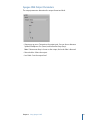
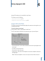
1
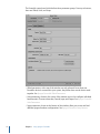
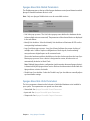
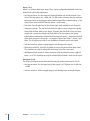
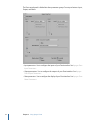
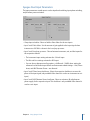
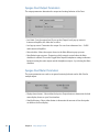
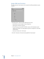
Logic Express 9
Working with Apogee Hardware
Copyright © 2009 Apple Inc. All rights reserved.
Your rights to the software are governed by the
accompanying software license agreement. The owner or
authorized user of a valid copy of Logic Express software
may reproduce this publication for the purpose of learning
to use such software. No part of this publication may be
reproduced or transmitted for commercial purposes, such
as selling copies of this publication or for providing paid
for support services.
The Apple logo is a trademark of Apple Inc., registered in
the U.S. and other countries. Use of the “keyboard” Apple
logo (Shift-Option-K) for commercial purposes without
the prior written consent of Apple may constitute
trademark infringement and unfair competition in violation
of federal and state laws.
Every effort has been made to ensure that the information
in this manual is accurate. Apple is not responsible for
printing or clerical errors.
Note: Because Apple frequently releases new versions
and updates to its system software, applications, and
Internet sites, images shown in this manual may be slightly
different from what you see on your screen.
Apple
1 Infinite Loop
Cupertino, CA 95014
408-996-1010
www.apple.com
Apple, the Apple logo, FireWire, and Logic are trademarks
of Apple Inc., registered in the U.S. and other countries.
Other company and product names mentioned herein
are trademarks of their respective companies. Mention of
third-party products is for informational purposes only
and constitutes neither an endorsement nor a
recommendation. Apple assumes no responsibility with
regard to the performance or use of these products.
Contents
Preface
5
5
5
6
An Introduction to Working with Apogee Hardware
About Using Apogee Hardware
About the Logic Express Documentation
Additional Resources
Chapter 1
7
7
9
9
14
Using Apogee’s Ensemble
Overview of the Apogee Control Panel
Apogee Ensemble Global Parameters
Apogee Ensemble Units Parameters
Apogee Ensemble Setup Buttons
Chapter 2
15
15
17
18
18
Using Apogee’s Duet
Overview of the Apogee Control Panel
Apogee Duet Input Parameters
Apogee Duet Output Parameters
Apogee Duet Meter Parameters
Chapter 3
19
19
20
21
Using Apogee’s ONE
Overview of the Apogee Control Panel
Apogee ONE Input Parameters
Apogee ONE Output Parameters
Chapter 4
23 Using Apogee’s GiO
23 Apogee GiO Control Panel
24 Apogee GiO Control Surface Assignments
3
Preface
An Introduction to Working with
Apogee Hardware
Apogee digital audio hardware offers a number of advanced features that can be controlled
by Logic Express. Logic Express offers a dedicated control panel that allows you to directly
configure Apogee’s Ensemble, Duet, ONE, and GiO hardware.
Note: The control panel and associated menu options are only available if supported
Apogee hardware is installed correctly with your system. For further information on
installation, see the manuals supplied with your Apogee device.
This preface covers the following:
• About Using Apogee Hardware (p. 5)
• About the Logic Express Documentation (p. 5)
• Additional Resources (p. 6)
About Using Apogee Hardware
This guide covers the setup and use of the following Apogee hardware devices in
Logic Express.
• Ensemble: See Using Apogee’s Ensemble.
• Duet: See Using Apogee’s Duet.
• ONE: See Using Apogee’s ONE.
• GiO: See Using Apogee’s GiO.
About the Logic Express Documentation
Logic Express comes with various documents that will help you get started as well as
provide detailed information about the included applications.
• Logic Express User Manual: This onscreen manual provides comprehensive instructions
for using Logic Express to set up a recording system, compose music, edit audio and
MIDI files, and output audio for CD productions.
• Exploring Logic Express: This booklet provides a fast-paced introduction to the main
features and tasks in Logic Express, encouraging hands-on exploration for new users.
5
• Logic Express Control Surfaces Support: This onscreen manual describes the configuration
and use of control surfaces with Logic Express.
• Logic Express Instruments: This onscreen manual provides comprehensive instructions
for using the powerful collection of instruments included with Logic Express.
• Logic Express Effects: This onscreen manual provides comprehensive instructions for
using the powerful collection of effects included with Logic Express.
• Logic Express Working with Apogee Hardware: This onscreen manual describes the use
of Apogee hardware with Logic Express.
Additional Resources
Along with the documentation that comes with Logic Express, there are a variety of other
resources you can use to find out more.
Release Notes and New Features Documents
Each application offers detailed documentation that covers new or changed features and
functions. This documentation can be accessed in the following location:
• Click the Release Notes and New Features links in the specific application’s Help menu.
Logic Express Website
For general information and updates, as well as the latest news on Logic Express, go to:
• http://www.apple.com/logicexpress
Apple Service and Support Websites
For software updates and answers to the most frequently asked questions for all Apple
products, go to the general Apple Support webpage. You’ll also have access to product
specifications, reference documentation, and Apple and third-party product technical
articles.
• http://www.apple.com/support
For software updates, documentation, discussion forums, and answers to the most
frequently asked questions for Logic Express, go to:
• http://www.apple.com/support/logicexpress
For discussion forums for all Apple products from around the world, where you can search
for an answer, post your question, or answer other users’ questions, go to:
• http://discussions.apple.com
6
Preface
An Introduction to Working with Apogee Hardware
Using Apogee’s Ensemble
1
Apogee Ensemble hardware can be controlled by Logic Express.
This chapter covers the following:
• Overview of the Apogee Control Panel (p. 7)
• Apogee Ensemble Global Parameters (p. 9)
• Apogee Ensemble Units Parameters (p. 9)
• Apogee Ensemble Setup Buttons (p. 14)
Overview of the Apogee Control Panel
The Apogee control panel automatically displays the parameter set that applies to your
connected audio device.
µ
To open the Apogee control panel
Choose Options > Audio > Open Apogee Control Panel.
7
The Ensemble control panel is divided into three parameter groups. From top to bottom,
these are Global, Units, and Setup.
• Global parameters, at the top of the window, are only relevant if more than one
Ensemble device is connected to your system; they define how several devices work
together. See Apogee Ensemble Global Parameters.
• Units parameters, shown in the center of the window, are used to configure individual
hardware units. There are three tabs; General, Input, and Output. See Apogee Ensemble
Units Parameters.
• Setup parameters, shown at the bottom of the window, allow you to save and load
different Apogee hardware configurations. See Apogee Ensemble Setup Buttons.
8
Chapter 1 Using Apogee’s Ensemble
Apogee Ensemble Global Parameters
The Global parameters at the top of the Apogee hardware control panel determine which
Apogee Ensemble hardware device is used.
Note: Only one Apogee FireWire device can be controlled at a time.
• Unit Select pop-up menu: The Unit Select pop-up menu defines the hardware device
(when multiple units are connected). The parameters of the selected device are displayed
in the tabs below.
• Identify Unit checkbox: Select the Identify Unit checkbox to illuminate all LEDs on the
corresponding hardware interface.
• Loop Sync Master pop-up menu: Loop Sync Master facilitates the proper clocking of
multiple units. It allows simple reconfiguration of clock signals, accommodating
nonsynchronous digital inputs on all connected units.
Choose the hardware unit that should be used as the clock master from the Loop Sync
Master pop-up menu. Once a device is designated as master, all other units are
automatically locked to its Word Clock.
Note: Multiple Apogee device configuration (and interaction between Apogee devices)
is determined by the Apogee driver version. Refer to the information included with the
Apogee driver or device for details.
• Disable Loop Sync checkbox: Select the Disable Loop Sync checkbox to manually adjust
synchronization settings.
Apogee Ensemble Units Parameters
The Units parameters determine the behavior of individual hardware units installed in
your system. These parameters are spread over three tabs:
• General tab. See Apogee Ensemble General Parameters.
• Inputs tab. See Apogee Ensemble Inputs Parameters.
• Outputs tab. See Apogee Ensemble Outputs Parameters.
Chapter 1 Using Apogee’s Ensemble
9
Apogee Ensemble General Parameters
Click the General tab to set hardware features such as the clock source, UV22HR dithering
algorithm, and level meter behavior.
• Source pop-up menu: Sets the clock source for the chosen unit. Options are Internal,
Optical, Coax, and Word Clock.
• Optical In and Optical Out pop-up menus: Choose the protocol for the optical input and
output channels. Options are ADAT/SMUX and S/PDIF.
• UV22HR pop-up menu: Choose the target signal path for the UV22HR dithering algorithm.
Options are Off, Analog In 1–2, Analog In 3–4, Analog In 5–6, Analog In 7–8, Optical In
1–2, Optical In 3–4, Optical In 5–6, Optical In 7–8, S/PDIF In, and S/PDIF Out.
• Conversion and SRC Rate pop-up menus: The Conversion pop-up menu allows you to
activate or deactivate sample rate conversion for the S/PDIF Input or Output.
If sample rate conversion is activated for the S/PDIF Out channel, you can set the
destination sample rate in the SRC Rate pop-up menu.
• Level Meter Display pop-up menu: Determines the type of metering display shown on
the front panel of your Ensemble. Options are Input Level, Output Level, or Off.
10
Chapter 1 Using Apogee’s Ensemble
• Hold and Clear Overloads parameters: Select the Hold Overloads checkbox to permanently
display overloads on the Ensemble’s front panel overload LEDs.
Click the Clear Overloads button to reset the overload LEDs.
• CD Mode checkbox: Select this checkbox to engage CD mode, which sends a 44.1 kHz,
16-bit stereo signal to the S/PDIF output, regardless of the input. Activating this
checkbox automatically switches the Conversion pop-up menu to S/PDIF Out, the SRC
Rate pop-up menu to 44.1 kHz, and the UV22HR pop-up menu to S/PDIF Out. If you
change any of these automatically set parameters, the CD Mode checkbox is disabled.
Apogee Ensemble Inputs Parameters
Click the Inputs tab to configure the inputs of your Ensemble hardware. The tab contains
four identical parameter sets for mic inputs 1 to 4, and a separate parameter section for
line inputs 5 to 8.
Chapter 1 Using Apogee’s Ensemble
11
Inputs 1 to 4
Inputs 1 to 4 feature built-in pre-amps. These can be configured individually via the four
identical sets of Pre-Amp parameters.
• Level pop-up menu: Sets the respective channel between mic and line inputs. If you
choose the Line option, the +4 dBu and −10 dBV options (shown in the pop-up menu
below) are used to set the reference level of the line input. All mic-related settings—Gain,
Group, Phase Invert, and 48V Phantom Power—are dimmed.
• Gain slider: Sets the gain level of the chosen input (only available for mic channels).
• Group pop-up menu: The gain controls of the mic inputs can be assigned to a group.
Groups link the Gain sliders of mic inputs. Changing the Gain slider of any mic input
assigned to a group also changes the Gain sliders of all mic inputs in the group.
Individual gain relationships (relative levels between mic inputs)—at the time the Gain
sliders were assigned to the group—are retained. Options are Group 1, Group 2, and
None. The Group pop-up menu is only available to channels used as mic inputs.
• Soft Limit checkbox: Select to apply Apogee’s soft limiting to the inputs.
• Phase Invert checkbox: Select this checkbox to reverse the phase of the input signal.
This checkbox can only be activated if the channel is used as a mic input.
• 48V Phantom Power checkbox: Select to activate a 48 volt phantom power supply for
inputs 1 to 4. This checkbox can only be activated if the channel is used as a mic input.
Line Inputs 5 to 8
The Analog Line Input section offers the following parameters for line inputs 5 to 8:
• Level pop-up menu: Sets the input level of line inputs 5 to 8. Options are +4 dBu and
−10 dBV.
• Soft Limit checkbox: Select to apply Apogee’s soft limiting to the analog line inputs.
12
Chapter 1 Using Apogee’s Ensemble
Apogee Ensemble Outputs Parameters
Click the Outputs tab to configure the outputs of your Ensemble hardware.
• Headphone 1 and 2 Source pop-up menus: Determine which output pair is sent to the
respective headphone output. Options are Analog Out 1–2, Analog Out 3–4, Analog Out
5–6, Analog Out 7–8, Optical Out 1–2, Optical Out 3–4, Optical Out 5–6, Optical Out
7–8, and S/PDIF Out.
• Headphone 1 and 2 Level sliders: Set the level of the respective headphone output.
• Format pop-up menu: Choose the output channels that you want to control with the
Main Output Level slider. Values are Stereo, 5.1 Surround, and 7.1 Surround.
• Output Level slider: Sets the level of channels chosen in the Format pop-up menu.
• Channel pop-up menus: Choose either +4 dBu or −10 dBV in the respective Channel
pop-up menu to determine the reference level for each of the eight analog line outputs.
Chapter 1 Using Apogee’s Ensemble
13
Apogee Ensemble Setup Buttons
The bottom of the Apogee hardware control panel offers three buttons that allow you
to save and load your configuration settings.
• Recall Setup from Project button: Loads the configuration saved with a project.
• Load Setup button: Opens a dialog, allowing you to load a stored configuration.
• Save Setup button: Opens a dialog, allowing you to save the current configuration.
14
Chapter 1 Using Apogee’s Ensemble
Using Apogee’s Duet
2
Apogee Duet hardware can be controlled by Logic Express.
This chapter covers the following:
• Overview of the Apogee Control Panel (p. 15)
• Apogee Duet Input Parameters (p. 17)
• Apogee Duet Output Parameters (p. 18)
• Apogee Duet Meter Parameters (p. 18)
Overview of the Apogee Control Panel
The Apogee control panel automatically displays the parameter set that applies to your
connected audio device.
µ
To open the Apogee control panel
Choose Options > Audio > Open Apogee Control Panel.
15
The Duet control panel is divided into three parameter groups. From top to bottom: Input,
Output, and Meter.
• Input parameters: Use to configure the inputs of your Duet interface. See Apogee Duet
Input Parameters.
• Output parameters: Use to configure the outputs of your Duet interface. See Apogee
Duet Output Parameters.
• Meter parameters: Use to configure the display of your Duet interface. See Apogee Duet
Meter Parameters.
16
Chapter 2 Using Apogee’s Duet
Apogee Duet Input Parameters
The input parameters control aspects such as input level switching, input phase switching,
and phantom power activation.
• Group Inputs checkbox: Select to link the Gain sliders for the two inputs.
• Input 1 and 2 Gain sliders: Set the amount of gain applied to the input signal when
instrument or XLR Mic is chosen in the Level pop-up menu.
• Input 1 and 2 Level pop-up menus: Choose between instrument, mic, and line inputs for
the respective channel.
• The Instrument input setting activates the 1/4 inch input.
• The Mic and Line settings activate the XLR input.
• You can choose between two line options, +4 dBu and −10 dBV, when setting the
reference level of the line input. All mic and instrument-related settings—Gain, Phase
Invert, and 48V Phantom Power—are dimmed.
• Input 1 and 2 Phase Invert checkboxes: Select the respective checkbox to reverse the
phase of the input signal (only available if the channel is used as an instrument or mic
input).
• Input 1 and 2 48V Phantom Power checkboxes: Select to activate a 48 volt phantom
power supply for the respective input. This checkbox is only available if the channel is
used as a mic input.
Chapter 2 Using Apogee’s Duet
17
Apogee Duet Output Parameters
The output parameters determine the output and muting behavior of the Duet.
• Level slider: Sets the output level. If you set the (Output) Level pop-up menu to
Instrument Amplifier, this slider has no effect.
• Level pop-up menu: Determines the output. You can choose between Line −10 dBV
and Instrument Amplifier.
• Mute checkbox: Mutes the output chosen in the Mute Behavior pop-up menu.
• Mute Behavior pop-up menu: Determines which output is muted when the Mute
checkbox is selected. Choose the Toggle Main Output/Headphones setting to alternate
between muting the main output and the headphone output—by selecting the Mute
checkbox.
Apogee Duet Meter Parameters
The meter parameters are used to set general metering behavior and to link Gain for
multiple inputs.
• Display shows buttons: Select either the Input or Output button to determine the level
meter display shown on your Duet interface.
• Peak Hold buttons: Select either button to determine the amount of time that peaks
are held on the Duet display.
18
Chapter 2 Using Apogee’s Duet
Using Apogee’s ONE
3
Apogee ONE hardware can be controlled by Logic Express.
This chapter covers the following:
• Overview of the Apogee Control Panel (p. 19)
• Apogee ONE Input Parameters (p. 20)
• Apogee ONE Output Parameters (p. 21)
Overview of the Apogee Control Panel
The Apogee control panel automatically displays the parameter set that applies to your
connected audio device.
µ
To open the Apogee control panel
Choose Options > Audio > Open Apogee Control Panel.
The ONE control panel is divided into two parameter groups: Input and Output.
• Input parameters: Use to configure the inputs of your ONE interface. See Apogee ONE
Input Parameters.
• Output parameters: Use to configure the outputs of your ONE interface. See Apogee
ONE Output Parameters.
19
Apogee ONE Input Parameters
The input parameters control aspects such as input level switching and phantom power
activation.
• Input pop-up menu: Choose one of the following input sources:
• Int(ernal) Mic activates the built-in electret microphone.
• Ext(ernal) Mic activates the XLR input.
• External Phantom-powered Mic (Ext 48V Mic) activates a 48 volt phantom power
supply for the XLR input. This setting applies only when a microphone is connected
to the XLR input.
• Inst(rument) activates the 1/4 inch input.
• Gain slider: Determines the amount of gain applied to the input signal.
20
Chapter 3 Using Apogee’s ONE
Apogee ONE Output Parameters
The output parameters determine the output format and level.
• Output pop-up menu: Determines the output gain. You can choose between
Speaker/Headphone Out (Stereo) and Instrument Amp (Amp).
Note: If Instrument Amp is chosen as the output, the Level slider is dimmed.
• Mute checkbox: Mutes the output.
• Level slider: Sets the output level.
Chapter 3 Using Apogee’s ONE
21
Using Apogee’s GiO
4
Apogee GiO hardware can be controlled by Logic Express.
This chapter covers the following:
• Apogee GiO Control Panel (p. 23)
• Apogee GiO Control Surface Assignments (p. 24)
Apogee GiO Control Panel
The Apogee control panel automatically displays the parameter set that applies to your
connected audio device.
µ
To open the Apogee control panel
Choose Options > Audio > Open Apogee Control Panel.
The GiO control panel is divided into two parameter groups: Input and Output.
• Instrument Gain slider: Use this slider to determine the amount of gain applied to the
input signal..
• Level slider: Sets the output level.
• Mute checkbox: Mutes the output.
• Output buttons: Select either Line/Headphone or Instrument Amplifier to determine
the output gain.
Note: If Instrument Amplifier is chosen as the output, the Level slider is dimmed.
23
Apogee GiO Control Surface Assignments
Logic Express automatically supports the Apogee GiO control surface functions.
Assignments of Apogee GiO interface elements to Logic functions are covered in the
following sections:
• Apogee GiO Transport Buttons
• Apogee GiO Effect, Next, and Previous Buttons
Note: Connection of an (optional) foot pedal to the Expression Pedal input on the rear
panel of the Apogee GiO will send MIDI Controller 11.
Apogee GiO Transport Buttons
The following table outlines the transport controls and their assignments:
Control
Assignment
RECORD
Record. Command is executed when the button is released. Button
is lit when active.
RTZ
Go to project start. Command is executed when the button is
released. Button is lit when the playhead is at the start of the project.
REW
Each press moves the playhead backward by one bar. Hold down
to move the playhead backward over multiple bars.
F FWD
Each press moves the playhead forward by one bar. Hold down to
move the playhead forward over multiple bars.
PLAY/STOP
Play or Stop. Command is executed when the button is released.
Button is lit in playback or record mode.
Apogee GiO Effect, Next, and Previous Buttons
The following table outlines the Effect 1–5, Next, and Previous buttons and their
assignments.
Note: The Effect 1–5 buttons always operate on the first Pedalboard plug-in inserted in
the selected track’s channel strip. When no Pedalboard plug-in is inserted in the selected
track’s channel strip, these buttons have no function. Inserting, deleting, or reordering
pedals in the Pedalboard plug-in automatically update the GiO’s Effect 1–5 button LEDs.
24
Control
Assignment
Previous
Previous Channel Strip or Plug-In Setting or EXS Instrument
Effect 1
Activates or bypasses the pedal in slot 1 of the Pedalboard plug-in.
The LED is brightly lit when active, dimly lit when bypassed, or off
when no pedal is in slot 1.
Effect 2
Activates or bypasses the pedal in slot 2 of the Pedalboard plug-in.
The LED is brightly lit when active, dimly lit when bypassed, or off
when no pedal is in slot 2.
Chapter 4 Using Apogee’s GiO
Control
Assignment
Effect 3
Activates or bypasses the pedal in slot 3 of the Pedalboard plug-in.
The LED is brightly lit when active, dimly lit when bypassed, or off
when no pedal is in slot 3.
Effect 4
Activates or bypasses the pedal in slot 4 of the Pedalboard plug-in.
The LED is brightly lit when active, dimly lit when bypassed, or off
when no pedal is in slot 4.
Effect 5
Activates or bypasses the pedal in slot 5 of the Pedalboard plug-in.
The LED is brightly lit when active, dimly lit when bypassed, or off
when no pedal is in slot 5.
Next
Next Channel Strip or Plug-In Setting or EXS Instrument
Chapter 4 Using Apogee’s GiO
25