1
BBT181 Gstr CDi Conv T&S IssB
4/5/06
11:21
Page 10
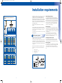
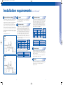
Condensate termination and route
Flue terminal positioning
External condensate pipe work
The condensate connection on the Worcester appliances is in 22mm
plastic. The pipe should be extended and directed away from the
appliance with a constant minimum fall of 2.5 degrees or 50mm in
every metre.
All Worcester condensing boilers have within a syphonic condensate
trap. Rather than the condensate constantly dripping into the
discharge pipe, the condensate is collected into a trap which
releases it in 100ml quantities. This will help prevent freezing
occurring.
The condensate pipe can terminate into any one of five areas:
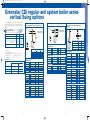
RSF horizontal and vertical
Key to illustration
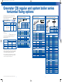
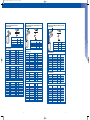
Minimum dimensions of flue terminal positions for
balanced room sealed flues with fanned draught:
Terminal Position
Directly below an opening, air brick, opening windows etc.
Above an opening, air brick, opening window etc.
Horizontally to an opening, air brick, opening window etc.
Below gutters, soil pipes or drain pipes
Below eaves
Below balconies or car port roof (lowest point)
From a vertical drain pipe or soil pipe
From an internal or external corner or to a boundary
alongside the terminal
I Above ground, roof or balcony
J From a surface or boundary facing the terminal
K From a terminal facing the terminal
L2 From an opening in the car port
(e.g. door, window) into the dwelling
M Vertically from a terminal on the same wall
N Horizontally from a terminal on the same wall
O From a non-combustible vertical structure on the roof
P Above intersection with the roof
Q Adjacent to windows or openings on pitched and flat roofs
R Below windows or openings on pitched roofs
Wherever possible the condensate discharge pipe work should be
routed and terminated internally. Should this not be possible, and the
only available route is external, the following conditions should be
observed:
Internal sink/washing
machine drain
Internal waste drainage system
The pipe work length should be kept to a minimum and the route
as vertical as possible
Where pipe work could be subjected to extreme cold or wind chill,
a weather proof insulation should be used. Alternatively, the
condensate pipe work could be increased to a minimum
32mm without the requirement to insulate
Q
Q
R
Pipe work connections
and casing dimensions
C
Cabinet dimensions
A
B
C
Soil and vent stack
750mm*
440mm
360mm
*760mm to top of casing front
External drainage system
The flue system must be installed and terminated in accordance with
the recommendations of BS 5440:Part 1.
CDi Conventional
G - 300mm x 100mmØ sealed plastic tube
B - Sink with integral overflow
H - Ground level
C - 21.5mmØ plastic condensate pipe
J - Drainage holes 50mm facing away from
building
A
Flow
22mm
D - External drain or gully
E - Internal soil and vent stack
K - Limestone chippings
B
Gas Inlet
22mm
F - Serviceable condensate trap (75mm min.)
L - Weather resistant insulation
C
Return
22mm
300mm
600mm**
1,200mm
1,200mm
1,500mm
300mm
*
*
600mm
2,000mm
1
In addition, the terminal should not be nearer than 150 mm (fanned draught) to an opening in the
building fabric formed for the purpose of accommodating a built-in element such as a window frame.
2
Not recommended.
spaced such that there is a gap of 50mm between the end of
the terminal and the guard.
3. In certain weather conditions, a white plume of condensation will
be emitted from the flue terminal and siting where this could be
a nuisance, eg. near security lighting, should be avoided.
4. The air inlet/outlet duct and the terminal of the boiler must not
be closer than 25mm to any combustible material. Detailed
recommendations on protection of combustible materials are
given in BS 5440:1.
Boiler location & clearances
External condensate absorption point (unsuitable for clay soil types)
A - Condensate from boiler syphon/trap
300mm**
** Care should be taken to ensure terminal siting does not cause a nuisance to adjacent properties.
General position
2. If a terminal is fitted less than 2 metres above a surface to
which people have access, then a guard must be fitted.
A terminal protective guard is available from Tower Flue
Components, Vale Rise, Tonbridge. Tel No. (01732) 351555.
The terminal guard must be securely fixed to the wall using
suitable plugs and corrosion resistance screws. The guard must
be symmetrically positioned about the terminal assembly and
B
300mm
300mm
300mm
75mm
200mm
200mm
150mm
* See instructions supplied with vertical flue kits.
1. The terminal must not cause an obstruction nor the discharge a
nuisance. Particular care should be exercised with regards to the
pluming of the flue gases and any increase in noise levels.
A
Min Distance
A1
B1
C1
D
E
F2
G
H
600mm
Bathrooms
Pipe work connections
The boiler can be installed in zones 2 or 3. If a mechanical or RF
mechanical timer or text display with room thermostat (IP 20 only)
is fitted the boiler can only be installed in zone 3.
600mm
750mm
A non mechanical timer can be installed in zone 2.
3
2
1
1
2
3
2250mm
See IEE wiring regulations. (See Technical Data for IP ratings).
Whilst all of the above methods are acceptable it is always the best
practice to terminate the condensate pipe via an internal waste
system. This will eliminate the need for any external condensate
pipe runs which can be susceptible to freezing in extreme weather.
Best practise is not to run external condensate pipe any further than
3m. If it is necessary to run more than 3m externally increase pipe
size to 35mm.
A
B
C
IMPORTANT: any switch or appliance control using mains
electricity must not be able to be touched by a person using the
bath or shower.
600mm
Electrical switches, fused spur and socket outlets must not be
situated in the bathroom.
750mm
All pipe work to the appliance must be cross bonded.
1
1
2
600mm radius
10
11
3
2250mm