1
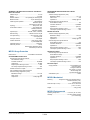
®
MegaPower CPU
ADMPCPU
Installation and Service Guide
8200-0421-01 E
MegaPower® CPU
Overview
Installation and Service Guide
The MegaPower CPU (MPCPU) is the control unit
for the MegaPower 3200 CCTV matrix switcher.
The control unit:
Rx
• Enables setup and control of cameras,
monitors, users, alarms, video recording and
data communications
Tx
• Provides two AD data lines and 16 RS-232
COM ports
ADMPCPU
• When two MPCPUs are connected together,
they double the AD data lines and RS-232
ports, and provide “hot switch” CPU operation
Contents
• Runs on a 12Vdc external power supply.
Overview........................................................................ 1
Safety Guidelines........................................................... 1
Installation ..................................................................... 2
Single MPCPU (A).................................................. 2
Second MPCPU (B)................................................ 2
Troubleshooting ............................................................. 5
Specifications ................................................................ 6
Declarations................................................................... 8
Appendix A: Hot Switch Setup....................................... 9
Appendix B: Detaching the MPU from the Port Module . 9
Appendix C: Basic ADMP3200 Matrix Switcher to
MPCPU Connection ............................................. 10
Appendix D: AD2088 Keyboard to MPCPU Connections
............................................................................. 11
Appendix E: ADCC200/300/1100 Keyboard to MPCPU
Connections.......................................................... 15
Appendix F: ADTTE Controller to MPCPU Connections
............................................................................. 19
Appendix G: Intellex to MPCPU Connections.............. 23
Appendix H: Computer to MPCPU Connections.......... 27
Appendix I: MPCPU to Dome Connection Examples... 30
Appendix J: MPCPU Site-to-Site at 9600 Baud
Connection Examples........................................... 31
Appendix K: Flip Cable Connections ........................... 33
The MPCPU consists of:
• MPU (Multiple Purpose Unit) module. Contains
the CPU and stores camera configuration data.
• Port module. Provides connections for camera
control data and CCTV input devices such as
keyboards.
Safety Guidelines
!
WARNING!
Installation and service is to be
performed by qualified personnel.
Wire in accordance with national wiring
regulations of the country of installation.
The unit is designed for use in general
purpose CCTV installations and has no
other function.
DO NOT exceed voltage and
temperature limits listed in these
instructions.
Use this unit in a clean, dust-free
environment.
The unit must be powered by the
provided Limited Power Source, certified
for the country of use.
© 2008 Sensormatic Electronics Corp.
MEGAPOWER CPU
INSTALLATION AND SERVICE GUIDE
8200-0421-01, REV. E
1 of 34
Second MPCPU (B)
Installation
The MPCPU unit is installed in a 48.3cm (19in)
equipment rack. Use screws supplied with the rack
or purchase screws separately.
The second MPCPU, designated “B”, is used to
double the AD data lines and RS-232 COM ports,
and as a backup in a hot switch setup (See
Appendix A).
Single MPCPU (A)
1. Insert MPCPU B in the equipment rack either
just above or just below MPCPU A and secure
using suitable hardware.
Refer to diagrams on pages 3 and 4 while
performing the following procedure. This MPCPU is
designated “A”.
2. Connect the ribbon cables between the two
units top to bottom, bottom to top.
1. Ensure the ribbon cable at the side of the MPU
module is connected to the module itself (and
not hanging).
3. Connect the power supply to the unit and plug
the supply into a standard ac outlet.
4. Attach the power supply module to the rack
using Velcro material supplied.
2. Insert MPCPU A in the equipment rack and
secure using suitable hardware.
5. Press the recessed Select button on the front
panel to select the CPU to drive the hot switch
setup.
3. Connect the power supply to the unit and plug
the supply into a standard ac outlet.
6. Move the AD Data Line switch on the rear of the
MPU to the up position to select data lines 3
and 4, and COM ports 17–32.
4. Attach the power supply module to the rack
using Velcro material supplied.
5. Connect the MPCPU to the necessary
equipment. See Appendices in this guide for
connection diagrams.
IMPORTANT! Make sure that AD Data Lines
and COM ports for MPCPUs A and B are not
set the same. Also make sure that software
settings for the COM ports are the same for
both MPCPUs.
6. Move the AD Data Line switch on the rear of the
MPU to the down position to select data lines 1
and 2, and COM ports 1–16.
7. Connect camera control data cables from the
bay switches and keyboards (for basic matrix
switching bay connections, see Appendix C; for
keyboard, Intellex, and computer connections,
see Appendices D–H).
7. Connect camera control data cables from the
bay switches and keyboards (for basic matrix
switching bay connections, see Appendix C; for
keyboard, Intellex, and computer connections,
see Appendices D–H).
MEGAPOWER CPU
INSTALLATION AND SERVICE GUIDE
8200-0421-01, REV. E
2 of 34
Indicators, Settings, and Connections
MPU Module
1
Port Module
5
Front
Rx
2
Tx
3
4
6
7
8
9
Front Panel (left to right)
1
Heart Beat
Upon power up or reset, blinks once for
ROM and RAM test completion (stays lit
and operation halts if either test fails).
Otherwise, blinks steadily to show
processor is operating.
4
5
Power Reset
Switch
Recessed button is used to reset the
MPCPU. Use a paper clip to press.
6
RS-232
COM Port
Module
Select
LEDs blink to show the COM ports
selected by a slide switch on the rear
panel: 1–16 or 17–32.
Note: If two units are hot switched
together, do not set both to the same
COM ports.
2
Broken Heart
Blinks once upon power up or reset. Then
only blinks when a fault occurs (along with
a beep). An error code displayed by the
Message Center indicates the fault.
3
Message
Center
Displays MPCPU error codes and the
following symbols:
FULL BEATING HEART = MPU is
communicating
• BROKEN HEART = MPU not
communicating
• NONE = no MPU in a hot switch setup
is communicating.
or
Network
Indicators
or NONE
7
• UP arrow = the selected unit in a hot
switch set up.
• DOWN arrow = the backup unit, if used.
Recessed button is used to select the
CPU that drives a dual unit hot switch
setup.
The message center displays the up
arrow to indicate the selected CPU.
or
• CLEAR circle = normal operation.
• DARK circle = a fault in the MPCPU.
8
RS-232
COM Port
Activity
LEDs show activity of COM ports 1–16 or
COM ports 17–32.
9
Data Line
Activity
Indicates data sent on the AD data lines
selected by a slide switch on the rear
panel: AD1–2 or AD3–4.
or
• CIRCULAR arrow = MPCPU with
ribbon cable connected to itself.
• OPPOSING arrows = two MPCPUs hot
switched together.
• NONE = CPUs are not communicating.
or
Indicates activity on the network.
• GREEN solid (Ethernet connectivity) or
flashing (Ethernet activity)
• AMBER ON (Ethernet 100Base-T) or
OFF (Ethernet 10Base-T)
or NONE
• Rx/Tx levels (show data activity). Bars
= maximum levels reached.
Rx
Tx
MEGAPOWER CPU
INSTALLATION AND SERVICE GUIDE
8200-0421-01, REV. E
3 of 34
Port Module
MPU Module
D
Rear
A
B
C
E
F
G
H
I
Rear Panel (left to right)
A
AD Data
Lines / COM
Ports
1–2 or 3–4
Control data is sent via these two BNC
connectors to switching bays, code
generation devices, and accessories that
are part of the matrix switching system.
Use high-speed coax RG59 or
equivalent. Plug a 75-ohm terminator
BNC into the last device.
Adjacent to these lines is a slide switch.
• UP position selects AD data lines 3–4
and COM ports 17–32 (indicated by the
top LED).
• DOWN position selects AD data lines
1–2 and COM ports 1–16 (indicated by
the bottom LED).
• UP/DOWN LEDs on the front panel
indicate the switch position.
D
Thumbnut
Turn counterclockwise to release the
MPU module from the port module.
E
Ethernet
Connection
LEDs in the connector indicate activity on
the network.
• GREEN solid (Ethernet connectivity) or
flashing (Ethernet activity)
• AMBER ON (Ethernet 100Base-T) or
OFF (Ethernet 10Base-T)
F
Video In/Out
BNC
VIDEO IN BNC (top) can be used for
manual snapshots. Connect this BNC to
a matrix switch VOM output dedicated for
snapshots.
Note: Manual snapshots reduce VOM
outputs used by monitors by one. Be sure
to terminate the video line (see Line
Termination Switches below). See
example in Appendix C.
The number of monitors, camera, and
camera PTZ functions controlled is as
follows:
DATA
LINE
B
RS-232
COM Ports
1–16 or
17-32
CAM
PTZ
1
1–64
MON
1–3200
1–1024
2
65–128
1–3200
1025–
2048
3
129–
192
1–3200
2049–
3072
4
193–
256
1–3200
3073–
3200
VIDEO OUT BNC (bottom) is not used.
RJ-45 connectors are used to connect
keyboards, alarm interfaces, video loss
modules, port expanders, access control,
and third party accessories.
G
Line
Termination
Switches
Use to terminate the Video In line, and
the two SensorNet or Manchester
connections. Press appropriate switch
down to terminate.
H
RS-422 /
SensorNet
Data
Connector
Default configuration is SensorNet and
can accept up to two SensorNet data
lines (for up to 508 cameras).
• Ch.1 is for 1-254 cameras (camera
numbers 1-254)
• Ch.2 is for 1-254 cameras (camera
numbers 255-508)
2
C
Alarms
NO
NC
1
Annunciators can connect to normally
open (NO) or normally closed (NC)
contacts depending on requirements.
The relay changes from the NC state if
one of the dual MPCPU’s is not
operating.
The relay will also change if two hotswitched MPCPUs are set to the same
com port setting (UP or DOWN).
See Data Connector Pin Assignments
(next page).
I
MEGAPOWER CPU
INSTALLATION AND SERVICE GUIDE
EASY CPU software can configure ports
to provide:
• Two connections that can be
independently set for SensorNet or
Manchester data transmission.
• Two additional connections for AD RS422/485 that can be independently
configured as RS-232 signals for AD
RS-422/485 distribution panels.
Power Input
12Vdc (+ in center).
8200-0421-01, REV. E
4 of 34
Protocol
SensorNet
Manchester
AD RS-422 / RS-485
AD RS-422 / RS-485
when configured to
RS-232 signals
Data Connector Pin
Assignments
Troubleshooting
Pin 5 ...............................Not used
Pin 6 .................. S+ (orange wire)
Pin 7 .................... S– (yellow wire,
right most pin)
Pin 5 ....................... Shield ground
Pin 6 ..................... S+ (black wire)
Pin 7 ......................S– (white wire,
right most pin)
Pin 1 ................. RX+ (yellow wire,
left most pin)
Pin 2 ................. RX– (brown wire)
Pin 3 ................ TX+ (orange wire)
Pin 4 .................. TX– (green wire)
Pin 5 ....................... Shield ground
Pin 2 ......................................RXD
Pin 4 ...................................... TXD
Pin 5 ................................. Ground
Parts Supplied
INDICATION
ACTION
Message center or
LEDs not on
Check AC connection.
Check 12Vdc power supply.
Broken or no heart
No CPU communication.
Dark circle in
message center
CPU failure. Press system reset
next to message center.
Disconnect the MPU from the
port module and reset the
module again.
No keyboard
communication
Check baud rate.
Check keyboard wiring.
Verify MPU and port modules
are connected (try other ports).
Press power reset next to LCD.
AD data line LEDs not
pulsing
Cycle power.
Press power reset next to LCD.
Reconnect MPU and port
modules.
Cannot communicate
with EASY CPU
software
Check line connections.
Check network settings on the
PC and MPCPU.
From the PC command prompt,
perform a ping test of the
MPCPU IP address.
No dome/PTZ direct
connection control
From a keyboard, perform a
ping test of the dome.
Check settings in the EASY
CPU “Direct Dome/PTZ
Connections” screen.
Check cable connections.
ADMPCPU Firmware (0201-0016-01)
MegaPower CPU Install Kit 0352-0228-01
Part
Qty
Part Number
Velcro Dual Lock
1
3200-0357-02
Connector, 3-Pin
1
2109-0510-03
Connector, 7-Pin
2
2109-0726-07
Connector, Plug
3
2109-0848-01
Power Supply
1
2025-0398-01
Power Cable, UK
1
6003-0221-01
Power Cable, US
1
6003-0239-01
Power Cable, Euro
1
6003-0240-01
Terminator, BNC
1
2113-0014-01
MEGAPOWER CPU
INSTALLATION AND SERVICE GUIDE
8200-0421-01, REV. E
5 of 34
SensorNet Dome Control Direct Connection
Specifications
Address range .............................................................1 to 254
Bit rate ................................................................... 230.4 Kbps
Network distance..................................1km (3300ft) per cable
segment with repeaters;
1.5km (5000ft) per cable
segment without repeaters
Maximum loads .............................32 per UTP cable segment
Cable segment repeaters ..............................ADACSNETD(P)
distribution panel,
SensorNet junction box,
and fiber optics module
Topologies ............................. Daisy Chain, Backbone, or Star
Transmission medium ...........................Single, non-polarized,
unshielded twisted pair
UTP 22AWG (0.326mm2)
Terminating resistor ...........................120Ω, switch selectable
Physical layer .......................................... RS-485, transformer
isolated, 2-wire
Data encoding ...................................... BiPhase-Space; FM-0
Link layer framing ................................................ SDLC/HDLC
Link layer channel ........................... Bi-directional, half duplex
Collision avoidance ..................................Host primary polling
by selected MPCPU
Application protocol ................................................ Proprietary
Secondary devices ............................ Dome, ADACSNETD(P)
distribution panels,
SensorNet junction boxes
Dome firmware update ....................ADACSNET USB module
MegaPower 3200 Operational
Bandwidth .........................................................................17MHz
Frequency response ........................................ ±0.5dB to 12MHz
Signal-to-noise ratio ......................... 65dB (Vp-p vs. Vrms noise)
Crosstalk:
Adjacent channels....................................–55dB (at 3.58MHz)
Input-to-input ............................................–70dB (at 3.58MHz)
Differential delay ..................................................................±1.0°
Differential phase .................................................... 1.5° or better
Differential gain ..................................................... 1.0% or better
Tilt ......................................................................... 0.5% or better
Gain.......................................................................... Unity (±1dB)
Return loss (input/output).................................................. >40dB
DC level (video signal) .............................................................0V
Switching...................................................Complete switching of
cross-point matrix,
EIA RS-170 and NTSC,
CCIR and PAL
Switching speed ....................................Less than 20ms (typical)
Keyboard/Receiver
control time.............................................................20ms (typical)
Phase adjustment ....................................... 180° vertical interval
adjustment for switching bay
Non-volatile memory ............................. Setup information saved
in permanent flash memory
On-screen text..............................................................Date/time,
video input number,
video input title,
site number,
site title monitor status,
user/keyboard number
Character set......................................................... Alpha numeric
Manchester Dome / PTZ Device Direct Connection
Address range ...............................................................1 to 64
Bit rate ........................................................................ 31 Kbps
Network distance ............................................. 1.5km (5000ft)
Maximum loads ............................... 3 per STP cable segment
Cable segment repeaters ..............................ADACSNETD(P)
distribution panel,
AD1691(F-1) distributor,
and fiber optics module
Topology............................................................... Daisy Chain
Transmission medium ................................Single twisted pair
Belden 8760 18AWG (0.823mm2)
polarized, shielded
Terminating resistor ....................120 ohms, switch selectable
Physical layer .......................................... RS-485, transformer
isolated, 2-wire
Data encoding .......................................................Manchester
Link layer framing ................................................... Proprietary
Link layer channel .......................................................Simplex
Application protocol ................................................ Proprietary
Secondary devices ....................................Dome, PTZ device,
ADSNETD(P) distribution panel,
And AD1691(F-1) distributor
MPCPU Electrical
AC-DC Power Supply
Operational rating................................ 100–240Vac, 50-60Hz,
0.4A, 42VA
Operational limit ..................................... 90-265Vac, 47–63Hz
Power consumption...........................0.5A max at 90Vac input
Protection .................................... Internal primary current fuse
Inrush limiting
Power to MPU ...........................................12Vdc, 1.25A, 15W
Certified Limited Power
Source, NEC Class 2
MPCPU Connections
Power input ..................................................................... IEC 320
Video inputs ............................... 0.5 to 2.0Vp-p, composite BNC
RS-232 ports ...................................... RJ-45 modular 8-pin jacks
AD data line out...............................................2 BNC connectors
Dome/PTZ direct connection............................2 Euro-style 7-pin
removable plug
3.81mm terminal blocks
MEGAPOWER CPU
INSTALLATION AND SERVICE GUIDE
8200-0421-01, REV. E
6 of 34
AD RS-422 / RS-485 Protocol for Dome / PTZ Device
Direct Connection
AD RS-422/RS-485 Dome/PTZ Device Direct
Connection
Address range............................................................. 1 to 100
Bit rate........................................................................4.8 Kbps
Network distance.................. 1km (3300ft) per cable segment
Maximum loads ..................................... 10 per cable segment
Cable segment repeaters..................................ADAC422D(P)
distribution panel,
and RS-422 junction box
Topology ...................................................... Daisy Chain, Star
Transmission medium................................. Two twisted pairs
22AWG (0.326mm2)
polarized, shielded
Physical layer................................ RS-485, 4-wire, or RS-232
Data encoding ...................................Start bit and one stop bit
Link layer framing.................................. Asynchronous, 8 data
and 0 parity bits
Link layer channel ...................................................Full duplex
Collision avoidance .................................. Host primary polling
by selected MPCPU
Application protocol................................................ Proprietary
Secondary devices........................................................ Dome,
ADAC422D(P) distribution panel,
And RS-422 junction box
Transient Voltage Suppressors (TVS):
Breakdown voltage.................................................7.6–9.3v
Peak current .................................................................. 40A
Capacitance ...............................................2000pF @ 1kHz
Gas discharge tube impulse rated at:
DC breakdown voltage ...................................................90v
Insulation resistance............................................ 10,000MΩ
Capacitance ..........................................................2pF max.
8/20µs impulse discharge current ............................... 10kA
Ten 8/20µs impulses discharge current ........................ 5kA
RS-232 Com Ports
Transient Voltage Suppressors (TVS):
Breakdown voltage................................................ 7.6–9.3V
Peak current .................................................................. 40A
Capacitance ...............................................2000pF @ 1kHz
Gas discharge tube impulse rated at:
DC breakdown voltage .................................................. 90V
Insulation resistance............................................ 10,000MΩ
Capacitance ..........................................................2pF max.
8/20µs impulse discharge current ............................... 10kA
Ten 8/20µs impulses discharge current ........................ 5kA
AD Data Line Ports
MPCPU Surge Protection
Gas discharge tube impulse rated at:
DC breakdown voltage .................................................. 90V
Insulation resistance............................................ 10,000MΩ
Capacitance ..........................................................2pF max.
8/20µs impulse discharge current ............................... 10kA
Ten 8/20µs impulses discharge current ........................ 5kA
Ethernet Port ..................................... 10/100 Base-T transformer
SensorNet/Manchester Ports
Gas discharge tube impulse rated at:
DC breakdown voltage ..................................................90V
Insulation resistance ........................................... 10,000MΩ
Capacitance ............................................................ 2pf Max
8/20µs impulse discharge current ................................10kA
Ten 8/20µs impulses discharge current .........................5kA
Isolation transformer coupled...................................2000Vrms
PTC re-settable fuse protects transformer
Transient Voltage Suppressors (TVS):
Breakdown voltage.................................................7.6–9.3V
Peak current...................................................................40A
Capacitance ...............................................2000pF @ 1kHz
DC Power Input
Surge protection .......................................PTC resettable fuse
protects regulator
Transguard rated at
60V, 250A, 1.5 Joules
Gas discharge tube
impulse rated at 10kA
Allowable drop out:........................................................150ms
MPCPU Mechanical
Mounting.................... Designed for EIA-310-D and IEC 60297-1
standard 482.6mm (19in)
electronic racks
Dimensions (H x W x D) ........................ 44.5 x 481.6 x 304.8mm
(1.75 x 19 x 12in.)
Weight ....................................................................3.2kg (10 lbs)
MPCPU Environmental
Operating temperature .........................0° to 40°C (32° to 104°F)
Humidity.............................................. 0 to 95% relative humidity
(non-condensing)
MEGAPOWER CPU
INSTALLATION AND SERVICE GUIDE
8200-0421-01, REV. E
7 of 34
Other Declarations
Declarations
Thank you for using American Dynamics products. We
support our products through an extensive and worldwide
network of dealers. The dealer, through whom you originally
purchased this product, is your point of contact if you have a
need for service or support. Our dealers are fully empowered
to provide the very best in customer service and support.
Dealers should contact American Dynamics at
(800) 507-6268 or (561) 912-6259 or on the web at
www.americandynamics.net.
Regulatory Type:
ADMPCPU-MPU
ADMPCPU-PORT
ADMPCPU-TRAY
Regulatory Compliance
WARRANTY DISCLAIMER: Sensormatic Electronics
Corporation makes no representation or warranty with respect
to the contents hereof and specifically disclaims any implied
warranties of merchantability or fitness for any particular
purpose.
EMC........................................................47 CFR, Part 15
EN 50130-4
EN 55022
EN 61000-3-2
EN 61000-3-3
NOTICE: The information in this manual was current when
published. The manufacturer reserves the right to revise and
improve its products. All specifications are therefore subject to
change without notice.
Safety ............................ UL/IEC/EN/CSA C22.2.60950-1
Environmental..................................... RoHS 2002/95/EC
WEEE 2002/96/EC
IP code X0
LIMITED RIGHTS NOTICE: For units of the Department
of Defense, all documentation and manuals were developed at
private expense and no part of it was developed using
Government Funds. The restrictions governing the use and
disclosure of technical data marked with this legend are set
forth in the definition of “limited rights” in paragraph (a) (15)
of the clause of DFARS 252.227.7013. Unpublished - rights
reserved under the Copyright Laws of the United States.
FCC COMPLIANCE: This equipment has been tested and
found to comply with the limits for a Class A digital device,
pursuant to part 15 of the FCC Rules. These limits are
designed to provide reasonable protection against harmful
interference when the equipment is operated in a commercial
environment. This equipment generates, uses, and can radiate
radio frequency energy and, if not installed and used in
accordance with the instruction manual, may cause harmful
interference to radio communications. Operation of this
equipment in a residential area is likely to cause harmful
interference in which case the user will be required to correct
the interference at their own expense.
TRADEMARK NOTICE: American Dynamics and
Sensormatic are trademarks or registered trademarks of
Sensormatic Electronics Corporation. Other product names
mentioned herein may be trademarks or registered trademarks
of Sensormatic or other companies.
COPYRIGHT: Under copyright laws, the contents of this
manual may not be copied, photocopied, reproduced,
translated or reduced to any electronic medium or machinereadable form, in whole or in part, without prior written
consent of Sensormatic Electronics.
EQUIPMENT MODIFICATION CAUTION: Equipment
changes or modifications not expressly approved by
Sensormatic Electronics Corporation, the party responsible for
FCC compliance, could void the user's authority to operate the
equipment and could create a hazardous condition.
MDR 10/2008
www.americandynamics.net
MEGAPOWER CPU
INSTALLATION AND SERVICE GUIDE
8200-0421-01, REV. E
8 of 34
Appendix A: Hot Switch Setup
Appendix B: Detaching the MPU
from the Port Module
The following applies when two MPCPUs connect
together for redundancy.
1. Loosen the thumbscrew in the back of the
assembly.
Selected Unit. Since both MPU modules are
actively processing incoming data, the term
“selected” identifies which unit is driving the lines.
2. Push the MPU module away from the Port
module, detaching it from the blind connector.
Backup Unit. An MPU module whose CPU is not
driving AD data lines and RS-232 COM ports.
However, it is still actively processing incoming
data so it can hot switch over if the selected unit
fails.
3. Remove the MPU module.
Thumbscrew
UP arrow in message center. Indicates an
MPCPU with AD data lines 1–2 and RS-232 COM
ports 1–16 selected.
DOWN arrow in message center. Indicates an
MPCPU with AD data lines 3–4 and RS-232 COM
ports 17–32 selected.
MEGAPOWER CPU
INSTALLATION AND SERVICE GUIDE
Port Module
MPU
Module
8200-0421-01, REV. E
9 of 34
Appendix C: Basic ADMP3200 Matrix Switcher to MPCPU Connection
(shown with one video output line dedicated to the Snapshot function)
Coax
AD Data Lines
MPCPU
Set Line Termination Switch
Coax
ADMP3200
T
E
S
T
/
E
X
P
A
N
S
I
O
N
IN
DATA LINE
OUT
IN
EXT. SYNC
OUT
To next
switching bay
or accessory,
or to a
75-ohm
terminator.
50/60 Hz
VOM output dedicated to Snapshots
Note: See Administrator’s Guide for
Snapshot and TFTP server configuration,
and for how to take Snapshot images.
MEGAPOWER CPU
INSTALLATION AND SERVICE GUIDE
8200-0421-01, REV. E
10 of 34
Appendix D: AD2088 Keyboard to MPCPU Connections
AD2088 > MPCPU (less than 2 meters (7 Feet))
MegaPower CPU Rear View
Ethernet Port
Do not connect the RS-232
keyboard to this port.
RS-232 Ports
K
5
4
7
S
4
5
7
0650-1000-01
Note: Set the MegaPower
CPU RS-232 baud rate to
1200 (default).
12Vdc @ 1.25A
K
Flip Cable
(6003-0047-01)
9Vac @ 1.3A
S
Flip Cable
(6003-0047-01)
AD2088 Keyboard
Note: Set the keyboard
RS-232 baud rate to
1200 (default).
MEGAPOWER CPU
INSTALLATION AND SERVICE GUIDE
8200-0421-01, REV. E
11 of 34
AD2088 > MPCPU (2– 305 meters (7–1000 feet) maximum at 1200 Baud)
MegaPower CPU Rear View
Ethernet Port
Do not connect the RS-232
keyboard to this port.
RS-232 Ports
Note: Set the MegaPower
CPU RS-232 baud rate to
1200 (default).
A
4
5
7
B
5
4
7
Belden 8770 (non-plenum)
Belden 88770 (plenum)
12Vdc @ 1.25A
Shield
A
Flip Cable
(6003-0047-01)
9Vac @ 1.3A
B
0650-0991-01
Flip Cable
(6003-0047-01)
Note: Connector plugs are supplied to help
reduce the number of terminal boxes used. Using
these plugs, cabling can go directly from box A to
the MPCPU, eliminating box B. See Appendix I
for connection information.
AD2088 Keyboard
Note: Set the keyboard
RS-232 baud rate to
1200 (default).
MEGAPOWER CPU
INSTALLATION AND SERVICE GUIDE
8200-0421-01, REV. E
12 of 34
AD2088 > AD2081 > MPCPU (less than 2 meters (7 feet))
Ethernet Port
Do not connect the RS-232
keyboard to this port.
MegaPower CPU Rear View
RS-232 Ports
Note: Set the MegaPower
CPU RS-232 baud rate to
4800 (1200 default).
0650-1000-01
K
S
Flip Cable
(6003-0047-01)
9Vac @ 1.3A
S
4
5
7
Flip Cable
(6003-0047-01)
12Vdc @ 1.25A
Flip Cable
(6003-0047-01)
K
5
4
7
Baud Rate
1 2
Off
Switch 1
Off
On
Switch 2
Off
AD2081
TO CPU
BAUD
RATE
DATA
AD2088 Keyboard
9Vac @ 500mA
Note: Set the keyboard
RS-232 baud rate to
1200 (default).
MEGAPOWER CPU
INSTALLATION AND SERVICE GUIDE
KEYBOARD
8-12V
A
B
C
D
Note: Set the CPU baud rate
to 4800 and the AD keyboard
to 1200 (4800 default).
8200-0421-01, REV. E
13 of 34
AD2088 > AD2081 > MPCPU (2–305 meters (7–1000 feet) maximum at 1200 Baud)
Ethernet Port
Do not connect the RS-232
keyboard to this port.
MegaPower CPU Rear View
RS-232 Ports
A
4
5
7
B
5
4
7
Note: Set the MegaPower
CPU RS-232 baud rate to
4800 (1200 default).
Belden 8770 (non-plenum)
Belden 88770 (plenum)
Flip Cable
(6003-0047-01)
12Vdc @ 1.25A
Shield
A
Flip Cable
(6003-0047-01)
0650-0991-01
Flip Cable
(6003-0047-01)
9Vac @ 1.3A
B
Baud Rate
1 2
Off
Switch 1
Off
On
Switch 2
Off
AD2081
TO CPU
BAUD
RATE
KEYBOARD
8-12V
DATA
AD2088 Keyboard
9Vac @ 500mA
Note: Set the keyboard
RS-232 baud rate to
1200 (default).
A
B
C
D
Note: Set the CPU baud rate
to 4800 and the AD keyboard
to 1200 (4800 default).
Note: Connector plugs are supplied to help
reduce the number of terminal boxes used. Using
these plugs, cabling can go directly from box A to
the MPCPU, eliminating box B. See Appendix I
for connection information.
MEGAPOWER CPU
INSTALLATION AND SERVICE GUIDE
8200-0421-01, REV. E
14 of 34
Appendix E: ADCC200/300/1100 Keyboard to MPCPU Connections
ADCC200/300/1100 > MPCPU (less than 2 meters (7 feet))
MegaPower CPU Rear View
Ethernet Port
Do not connect the RS-232
keyboard to this port.
RS-232 Ports
Note: Set the MegaPower
CPU RS-232 baud rate to
1200 (default).
12Vdc @ 1.25A
LK6
LK5
LK4
LK3
LK2
LK1
GND
485+
485–
Tx
Rx
MP-KMI
M
12Vdc @ 0.42A
K
1
2
3
Straight-thru Cable
(MP-CBL)
Note: Set the keyboard RS-232
baud rate to 1200 (RS-485 19200
default).
ADCC200/300 Keyboard
– OR –
Note: Set the keyboard RS-232
baud rate to 1200 (RS-232 1200
default).
ADCC1100 Keyboard
MEGAPOWER CPU
INSTALLATION AND SERVICE GUIDE
8200-0421-01, REV. E
15 of 34
ADCC200/300/1100 > MPCPU (2–305 meters (7–1000 feet) maximum at 1200 Baud)
Ethernet Port
Do not connect the RS-232
keyboard to this port.
MegaPower CPU Rear View
RS-232 Ports
Note: Set the MegaPower
CPU RS-232 baud rate to
1200 (default).
A
Rx
Tx
Gnd
B
Rx
Tx
Gnd
Belden 8770 (non-plenum)
Belden 88770 (plenum)
12Vdc @ 1.25A
Shield
MP-KMI
M
K
M
Straight-thru Cable
(MP-CBL)
12Vdc @ 0.42A
1
2
3
LK6
LK5
LK4
LK3
LK2
LK1
GND
485+
485–
Tx
Rx
B
LK6
LK5
LK4
LK3
LK2
LK1
GND
485+
485–
Tx
Rx
A
K
1
2
3
Straight-thru Cable
(MP-CBL)
Note: Set the keyboard RS-232
baud rate to 1200 (RS-485 19200
default).
ADCC200/300 Keyboard
– OR –
Note: Set the keyboard RS-232
baud rate to 1200 (RS-232 1200
default).
Note: Connector plugs are supplied to help
reduce the number of terminal boxes used. Using
these plugs, cabling can go directly from box A to
the MPCPU, eliminating box B. See Appendix I
for connection information.
ADCC1100 Keyboard
MEGAPOWER CPU
INSTALLATION AND SERVICE GUIDE
8200-0421-01, REV. E
16 of 34
ADCC200/300/1100 > AD2081 > MPCPU (less than 2 meters (7 feet))
Ethernet Port
Do not connect the RS-232
keyboard to this port.
MegaPower CPU Rear View
RS-232 Ports
Note: Set the MegaPower
CPU RS-232 baud rate to
4800 (1200 default).
12Vdc @ 1.25A
LK6
LK5
LK4
LK3
LK2
LK1
Flip Cable
(6003-0047-01)
GND
485+
485–
Tx
Rx
MP-KMI
M
12Vdc @ 0.42A
K
1
2
3
Straight-thru Cable
(MP-CBL)
Baud Rate
1 2
Note: Set the keyboard
RS-232 baud rate to
1200 (RS-485 19200
default).
Off
Switch 1
Off
On
Switch 2
Off
AD2081
TO CPU
BAUD
RATE
KEYBOARD
8-12V
DATA
9Vac @ 500mA
ADCC200/300 Keyboard
– OR –
A
B
C
D
Note: Set the CPU baud rate
to 4800 and the AD keyboard
to 1200 (4800 default).
Note: Set the keyboard RS-232
baud rate to 1200 (RS-232 1200
default).
ADCC1100 Keyboard
MEGAPOWER CPU
INSTALLATION AND SERVICE GUIDE
8200-0421-01, REV. E
17 of 34
ADCC200/300/1100 > AD2081 > MPCPU
(2–305 meters (7–1000 feet) maximum at 1200 Baud)
Ethernet Port
Do not connect the RS-232
keyboard to this port.
MegaPower CPU Rear View
RS-232 Ports
Note: Set the MegaPower
CPU RS-232 baud rate to
4800 (1200 default).
A
Rx
Tx
Gnd
B
Rx
Tx
Gnd
Belden 8770 (non-plenum)
Belden 88770 (plenum)
12Vdc @ 1.25A
Shield
MP-KMI
LK6
LK5
LK4
LK3
LK2
LK1
M
1
2
3
K
MP-KMI
Baud Rate
Straight-thru Cable
(MP-CBL)
Note: Set the keyboard
RS-232 baud rate to
1200 (RS-485 19200
default).
K
1
2
3
Straight-thru Cable
(MP-CBL)
M
12Vdc @ 0.42A
Flip Cable
(6003-0047-01)
GND
485+
485–
Tx
Rx
B
LK6
LK5
LK4
LK3
LK2
LK1
GND
485+
485–
Tx
Rx
A
1 2
Off
Switch 1
Off
On
Switch 2
Off
AD2081
TO CPU
BAUD
RATE
KEYBOARD
8-12V
DATA
9Vac @ 500mA
ADCC200/300 Keyboard
– OR –
A
B
D
C
Note: Set the CPU baud rate
to 4800 and the AD keyboard
to 1200 (4800 default).
Note: Set the keyboard RS-232
baud rate to 1200 (RS-232 1200
default).
ADCC1100 Keyboard
MEGAPOWER CPU
INSTALLATION AND SERVICE GUIDE
Note: Connector plugs are supplied to help
reduce the number of terminal boxes used. Using
these plugs, cabling can go directly from box A to
the MPCPU, eliminating box B. See Appendix I
for connection information.
8200-0421-01, REV. E
18 of 34
Appendix F: ADTTE Controller to MPCPU Connections
ADTTE Controller > MPCPU (less than 2 meters (7 feet))
MegaPower CPU Rear View
Ethernet Port
Do not connect the RS-232
keyboard to this port.
RS-232 Ports
0650-1000-01
Note: Set the MegaPower
CPU RS-232 baud rate to
1200 (default).
12Vdc @ 1.25A
J3 Connector
6003-0165-01
Pin
2
3
4
Description
24Vac
Gnd
24Vac
EIM
J3
1
0300-1000-01
J1
DB9
RJ45
9
J2
24Vac @ 28VA
Flip Cable
(6003-0047-01)
Note: Set the ADTTE RS-232
baud rate to 1200 (default).
ADTTE Controller
MEGAPOWER CPU
INSTALLATION AND SERVICE GUIDE
8200-0421-01, REV. E
19 of 34
ADTTE Controller > MPCPU (2–305 meters (7–1000 feet) maximum at 1200 Baud)
Ethernet Port
Do not connect the RS-232
keyboard to this port.
MegaPower CPU Rear View
RS-232 Ports
Note: Set the MegaPower
CPU RS-232 baud rate to
1200 (default).
Belden 8770 (non-plenum)
Belden 88770 (plenum)
A
4
5
7
Flip Cable
(6003-0047-01)
A
12Vdc @ 1.25A
B
Shield
B
5
4
7
Pin
2
3
4
J3
Description
24Vac
Gnd
24Vac
1
0300-1000-01
J1
DB9
RJ45
9
J2
24Vac @ 28VA
Flip Cable
(6003-0047-01)
6003-0165-01
0650-0991-01
EIM
J3 Connector
Note: Connector plugs are supplied to help
reduce the number of terminal boxes used. Using
these plugs, cabling can go directly from box A to
the MPCPU, eliminating box B. See Appendix I
for connection information.
Note: Set the ADTTE RS-232
baud rate to 1200 (default).
ADTTE Controller
MEGAPOWER CPU
INSTALLATION AND SERVICE GUIDE
8200-0421-01, REV. E
20 of 34
ADTTE Controller > AD2081 > MPCPU (less than 2 meters (7 feet))
Ethernet Port
Do not connect the RS-232
keyboard to this port.
MegaPower CPU Rear View
RS-232 Ports
J3 Connector
Pin
2
3
4
Note: Set the MegaPower
CPU RS-232 baud rate to
4800 (1200 default).
Description
24Vac
Gnd
24Vac
12Vdc @ 1.25A
J3
Flip Cable
(6003-0047-01)
EIM
1
0300-1000-01
J1
DB9
RJ45
9
J2
24Vac @ 28VA
Flip Cable
(6003-0047-01)
Baud Rate
1 2
Off
Switch 1
Off
On
Switch 2
Off
AD2081
TO CPU
BAUD
RATE
KEYBOARD
8-12V
DATA
A
9Vac @ 500mA
B
C
D
Note: Set the CPU baud rate
to 4800 and the AD keyboard
to 1200 (4800 default).
Note: Set the ADTTE RS-232
baud rate to 1200 (default).
ADTTE Controller
6003-0165-01
MEGAPOWER CPU
INSTALLATION AND SERVICE GUIDE
8200-0421-01, REV. E
21 of 34
ADTTE Controller > AD2081 > MPCPU
(2–305 meters (7–1000 feet) maximum at 1200 Baud)
Ethernet Port
Do not connect the RS-232
keyboard to this port.
MegaPower CPU Rear View
RS-232 Ports
A
4
5
7
B
5
4
7
Note: Set the MegaPower
CPU RS-232 baud rate to
4800 (1200 default).
Belden 8770 (non-plenum)
Belden 88770 (plenum)
A
B
12Vdc @ 1.25A
Flip Cable
(6003-0047-01)
0650-0991-01
0650-0991-01
Shield
J3 Connector
Pin
2
3
4
Description
24Vac
Gnd
24Vac
Baud Rate
1 2
Off
J3
Switch 1
Off
On
1
0300-1000-01
J1
DB9
RJ45
9
J2
Switch 2
Off
AD2081
TO CPU
24Vac @ 28VA
BAUD
RATE
KEYBOARD
8-12V
DATA
A
9Vac @ 500mA
Flip Cable
(6003-0047-01)
6003-0165-01
EIM
B
C
D
Note: Set the CPU baud rate
to 4800 and the AD keyboard
to 1200 (4800 default).
Flip Cable
(6003-0047-01)
Note: Set the ADTTE RS-232
baud rate to 1200 (default).
Note: Connector plugs are supplied to help
reduce the number of terminal boxes used. Using
these plugs, cabling can go directly from box A to
the MPCPU, eliminating box B. See Appendix I
for connection information.
ADTTE Controller
MEGAPOWER CPU
INSTALLATION AND SERVICE GUIDE
8200-0421-01, REV. E
22 of 34
Appendix G: Intellex to MPCPU Connections
Intellex > MPCPU via S3 Kit (less than 2 meters (7 feet))
MegaPower CPU Rear View
Ethernet Port
Do not connect the RS-232
keyboard to this port.
RS-232 Ports
Note: Set the MegaPower
CPU RS-232 baud rate to
1200 (default). Set the
Port Type to “Terminal.”
12Vdc @ 1.25A
Intellex Rear View
RJ-45 to DB-9
(2025-0294-01)
Note: Select “MUX” port under camera
handler of Intellex (1200 baud default).
Flip Cable
(6003-0047-01)
MEGAPOWER CPU
INSTALLATION AND SERVICE GUIDE
8200-0421-01, REV. E
23 of 34
Intellex > MPCPU via S3 Kit (2–305 meters (7–1000 feet) maximum at 1200 baud)
Ethernet Port
Do not connect the RS-232
keyboard to this port.
MegaPower CPU Rear View
RS-232 Ports
Belden 8770 (non-plenum)
Belden 88770 (plenum)
Shield
B
0650-0991-01
A
12Vdc @ 1.25A
Flip Cable
(6003-0047-01)
B
5
4
7
0650-0991-01
A
4
5
7
Note: Set the MegaPower
CPU RS-232 baud rate to
1200 (default). Set the Port
Type to “Terminal.”
Note: Connector plugs are supplied to help
reduce the number of terminal boxes used. Using
these plugs, cabling can go directly from box A to
the MPCPU, eliminating box B. See Appendix I
for connection information.
Intellex Rear View
RJ-45 to DB-9
(2025-0294-01)
Note: Select “MUX” port under camera
handler of Intellex (1200 baud default).
Flip Cable
(6003-0047-01)
MEGAPOWER CPU
INSTALLATION AND SERVICE GUIDE
8200-0421-01, REV. E
24 of 34
Intellex > MPCPU via USB to Serial Adapter (less than 2 meters (7 feet))
MegaPower CPU Rear View
Ethernet Port
Do not connect the RS-232
keyboard to this port.
RS-232 Ports
Note: Set the MegaPower
CPU RS-232 baud rate to
4800 (1200 default). Set the
Port Type to “Terminal.”
12Vdc @ 1.25A
Flip Cable
(6003-0047-01)
Intellex Rear View
Note: Set Edgeport COM
port to 4800 baud.
RDVUSB23201
RJ-45 to DB-9
(2025-0294-01)
MEGAPOWER CPU
INSTALLATION AND SERVICE GUIDE
8200-0421-01, REV. E
25 of 34
Intellex > MPCPU via USB > Serial Adapter
(2–15.2 meters (7–50 feet) maximum at 4800 baud)
MegaPower CPU Rear View
Ethernet Port
Do not connect the RS-232
keyboard to this port.
RS-232 Ports
A
4
5
7
B
5
4
7
Belden 8770 (non-plenum)
Belden 88770 (plenum)
12Vdc @ 1.25A
B
0650-0991-01
Shield
0650-0991-01
A
Note: Set the MegaPower
CPU RS-232 baud rate to
4800 (1200 default). Set the
Port Type to “Terminal.”
Note: Connector plugs are supplied to help
reduce the number of terminal boxes used. Using
these plugs, cabling can go directly from box A to
the MPCPU, eliminating box B. See Appendix I
for connection information.
Flip Cable
(6003-0047-01)
Flip Cable
(6003-0047-01)
Intellex Rear View
Note: Set Edgeport COM
port to 4800 baud.
RDVUSB23201
RJ-45 to DB-9
(2025-0294-01)
MEGAPOWER CPU
INSTALLATION AND SERVICE GUIDE
8200-0421-01, REV. E
26 of 34
Appendix H: Computer to MPCPU Connections
Computer > MPCPU PC Connection Using Ethernet Crossover Cable
MegaPower CPU Rear View
RS-232 Ports
Note: Default
MPCPU IP is
192.168.0.1.
Ethernet
Crossover
Cable
12Vdc @ 1.25A
Note: Set PC IP
to 192.168.0.2.
MEGAPOWER CPU
INSTALLATION AND SERVICE GUIDE
8200-0421-01, REV. E
27 of 34
Computer > MPCPU Connection Using a Hub or Router
MegaPower CPU Rear View
RS-232 Ports
Note: Default
MPCPU IP is
192.168.0.1.
12Vdc @ 1.25A
Hub / Router
MP-CBL
(Straight-Thru
Cable)
MP-CBL
(Straight-Thru
Cable)
Note: Set PC IP
to 192.168.0.2.
MEGAPOWER CPU
INSTALLATION AND SERVICE GUIDE
8200-0421-01, REV. E
28 of 34
Computer > MPCPU “Hot Switch” Connection Using a Hub or Router
MegaPower CPU Rear View No. 1
RS-232 Ports
Note: Set
MPCPU IP to
192.168.0.1.
Connect
Ribbon Cable
(top to bottom,
bottom to top)
12Vdc @ 1.25A
MegaPower CPU Rear View No. 2
RS-232 Ports
Note: Set
MPCPU IP to
192.168.0.2.
12Vdc @ 1.25A
Hub / Router
MP-CBL
(Straight-Thru
Cable)
MP-CBL
(Straight-Thru
Cable)
MP-CBL (Straight-Thru Cable)
Note: Set PC IP
to 192.168.0.3.
MEGAPOWER CPU
INSTALLATION AND SERVICE GUIDE
8200-0421-01, REV. E
29 of 34
Appendix I: MPCPU to Dome Connection Examples
Example 1
SNET Channel 1 for dome
address range 1–254*
MPCPU A
T
SNET Channel 1 for dome
address range 1–254*
MPCPU B
T
T
1
T
T
2
T
T
T
T
T
J-Box
30
T
T
Distribution
Panel
T
T
Example 2
SNET Channel 1 for dome
address range 1–254*
MPCPU A
T
SNET Channel 1 for dome
address range 1–254*
MPCPU B
T
* The address range is software configurable. See
“Configuring the Dome/PTZ Device Direct Connection” in
MPCPU Administrator’s Guide 8200-0421-03, Rev. E or
greater. To ensure the backup MPCPU performs
correctly, both MPCPUs must be programmed
identically.
MEGAPOWER CPU
INSTALLATION AND SERVICE GUIDE
Distribution
Panel
J-Box
T
T
T
T
8200-0421-01, REV. E
30 of 34
Appendix J: MPCPU Site-to-Site at 9600 Baud Connection Examples
MPCPU Site-to-Site (less than 15.2 meters (50 feet))
Ethernet Port
Do not connect the RS-232
keyboard to this port.
MegaPower CPU Rear View
RS-232 Ports
A
4
5
7
B
5
4
7
A
4
5
7
B
5
4
7
A
A
Belden 8770 (non-plenum)
Belden 88770 (plenum)
Note: The
MegaPower CPU
RS-232 baud rate is
typically set to
9600. Baud rate
must match that of
remote MegaPower 12Vdc @ 1.25A
CPU.
Belden 8770 (non-plenum)
Belden 88770 (plenum)
SITE 1
0650-0991-01
B
B
0650-0991-01
SITE 2
MEGAPOWER CPU
INSTALLATION AND SERVICE GUIDE
SITE 3
8200-0421-01, REV. E
31 of 34
MPCPU Site-to-Site (greater than 15.2 meters (50 feet))
MegaPower CPU Rear View
RS-232 Ports
SITE 1
A
4
5
7
Ethernet Port
Do not connect the RS-232
keyboard to this port.
B
5
4
7
A
4
5
7
Note: The
MegaPower CPU
RS-232 baud rate is
typically set to
9600. Baud rate
must match that of
remote MegaPower 12Vdc @ 1.25A
CPU.
B
5
4
7
A
A
Belden 8770 (non-plenum)
Belden 88770 (plenum)
Belden 8770 (non-plenum)
Belden 88770 (plenum)
0650-0991-01
B
Use a third party device
such as a converter and
suitable cable for distances
greater than 15.2m (50ft).
B
0650-0991-01
SITE 2
SITE 3
Note: The MegaPower CPU
RS-232 baud rate is typically
set to 9600. Baud rate must
match that of remote
MegaPower CPU.
MEGAPOWER CPU
INSTALLATION AND SERVICE GUIDE
Note: The MegaPower CPU
RS-232 baud rate is typically
set to 9600. Baud rate must
match that of remote
MegaPower CPU.
8200-0421-01, REV. E
32 of 34
Appendix K: Flip Cable
Connections
Connector plugs are supplied to help reduce the
use of terminal boxes. To connect the plugs to the
user supplied 0.326mm2 (22AWG) cabling, refer to
the table below. For how to connect wires, see
instructions supplied with the plugs.
Note: The maximum RS-232 cable distance
possible depends on the data rate, environment
electrical noise, and the inherent cable
capacitance. Using low capacitance 0.326mm2
(22AWG) or larger cable in a typical installation,
300m (1000ft) have been used at a 1200BPS data
rate, and 15m (50ft) at a 9600BPS data rate and
above.
MPCPU
Keyboard
Tx (Pin 4)
Rx (Pin 5)
Rx (Pin 5)
Tx (Pin 4)
Ground (Pins 2 and 7)
Ground (Pins 2 and 7)
MEGAPOWER CPU
INSTALLATION AND SERVICE GUIDE
8200-0421-01, REV. E
33 of 34
NOTES:
MEGAPOWER CPU
INSTALLATION AND SERVICE GUIDE
8200-0421-01, REV. E
34 of 34
Please visit our website for more information
www.americandynamics.net
© 2008 Sensormatic Electronics Corporation
Product specifications subject to change without notice.
Certain product names mentioned herein may be trade names
and/or registered trademarks of Sensormatic or other companies.
8200-0421-01 E