1
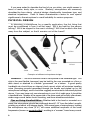
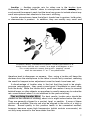
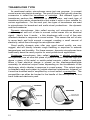
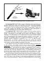
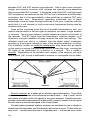
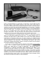
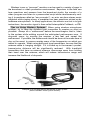
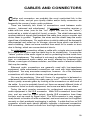
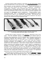
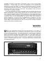
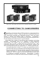
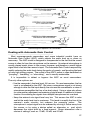
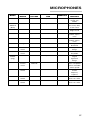
Guide
Audio Systems
A Shure Educational Publication
Audio
Systems
Guide
for
Video
Production
By Christopher Lyons
Video
Production
Guide
Preface . . . . . . . . . . . . . . . . . . . . . . . . . . . . . . . . . . . . . . . . 4
The Audio Chain . . . . . . . . . . . . . . . . . . . . . . . . . . . . . . . . . 5
Microphones . . . . . . . . . . . . . . . . . . . . . . . . . . . . . . . . . . . 5
Cables and Connectors . . . . . . . . . . . . . . . . . . . . . . . . . . 19
Mixers . . . . . . . . . . . . . . . . . . . . . . . . . . . . . . . . . . . . . . . . 21
Connecting to Camcorders . . . . . . . . . . . . . . . . . . . . . . . . 25
How to Handle Some Common Miking Situations . . . . . . 28
Troubleshooting . . . . . . . . . . . . . . . . . . . . . . . . . . . . . . . . 31
A Few Final Words . . . . . . . . . . . . . . . . . . . . . . . . . . . . . . 34
More Resources . . . . . . . . . . . . . . . . . . . . . . . . . . . . . . . . 35
Product Selection Charts . . . . . . . . . . . . . . . . . . . . . . . . . 36
About the Author . . . . . . . . . . . . . . . . . . . . . . . . . . . . . . . 38
PREFACE
B
ecause the video production field is enjoying such rapid
growth, keeping up with its technological advancements
is a real challenge. The equipment used in video production is
becoming more sophisticated, practical, and accessible every
day, and more and more people are getting involved with video
projects of all kinds.
Shure has been deeply involved with the audio side of
video production for many years. If there’s one thing we’ve
learned over this time, it’s that audio quality is a key element
that can “make or break” any video project. No matter how
creative and well-executed the visual aspects of a production
may be, these qualities can be completely negated by
lackluster audio. To a greater degree than most people
realize, video projects stand or fall on the basis of their audio.
This booklet is intended to help anyone involved with
video projects improve the audio quality of their productions.
It is not intended as a comprehensive study of the subject of
audio. Its real goal is to provide helpful tips, practical advice,
and a general knowledge of audio tools – all with the express
purpose of making video productions as clear, understandable, and impressive as possible.
Technological advances have helped us make great
strides over the years in communicating with one
another. As a leader in audio technology, Shure has played a
major role in this process. No matter what your involvement
with video production may be, we’re confident that Shure
products will help you achieve the highest possible level of
audio excellence in your work. And we hope this booklet will
help you use our products with the greatest effectiveness.
4
THE AUDIO CHAIN
A
lmost everyone has used a simple cassette tape recorder at one time
or another. In that instance, the process of recording sound is very simple:
press the Record button, talk into the microphone, and press the Stop button
when finished. In the world of audio-for-video, however, there may be many
pieces of equipment between the microphone and the videotape recorder. This
series of devices is collectively known as the audio chain. Common links in the
audio chain include a microphone (which transforms sound into an electrical
signal), a mixer (which adjusts the strength of the signal in relation to other
signals coming through the same system), and an equalizer, compressor, or
other signal processor (all of which merely alter the signal and are optional).
When it comes out of the mixer (or whatever extra signal processing
devices are required), the signal is ready to be fed into the audio input jack of a
video tape recorder or to an amplifier for playback through loudspeakers.
Audio chain
MICROPHONES:
DIFFERENT TYPES AND WHEN TO USE THEM
T
he first step in getting the sound of someone’s voice on to your videotape is the
microphone. Microphones serve a very basic purpose: to change acoustic
energy to electrical energy. They convert sound waves into an electrical signal
which can be modified, amplified, or recorded. Since the microphone’s function is
so basic, you might well ask why there are so many different kinds of microphones.
It’s simply because some types of microphones are better suited to certain uses
than others, just as pickup trucks are better than small sports cars for carrying large,
heavy loads. If you are familiar with the different types of microphones, and how
and when to use them, your productions will start sounding less like a home video
and more like the nightly news.
5
If you were asked to describe the kind of car you drive, you might answer in
terms of make, body style, or color. Similarly, microphones are commonly
described by four criteria: physical design, directionality, transducer type, and
electrical impedance. Each of these characteristics carries its own special
significance to the microphone’s overall suitability for various purposes.
PHYSICAL DESIGN
In choosing a microphone for a specific application, the first thing that
must be considered is how it will be used. Will it be held by the person
talking? Will it be clipped to the user’s clothing? Will it be located a few feet
away from the subject, so that it remains out of the frame?
MX393
WH10
MX202
WL183
SM58
SM89
U2/87
Examples of different microphone designs
Handheld — The most common kind of microphone is the handheld type. This
style is the most flexible, because it can be held by the user, mounted on a floor or
desk stand, or attached to a flexible “gooseneck” on a lectern. A good quality
handheld mic should have an internal shock mount which will minimize handling
noise (thumping sounds transmitted through the handle and picked up by the
microphone cartridge), and it should be ruggedly constructed to withstand physical
abuse. If you can have only one microphone in your kit of audio gear, it should be
a handheld mic. Models at the upper end of the price scale will usually offer clearer,
wider-range sound, better shock mounting, and more durable construction.
Tips on Using Handheld Mics: Whether held in the hand or mounted on a
stand, the microphone should be positioned about 6”-12” from the talker’s mouth,
pointing up at about a 45-degree angle. With some types of microphones, holding
the microphone very close (3”-6”) will cause additional emphasis of the lower
frequencies (known as proximity effect), resulting in a “warmer”, bass-heavy sound.
6
Lavalier — Another popular mic for video use is the lavalier type.
Historically, the word “lavalier” refers to microphones which are hung on a
cord around the wearer’s neck, but the term has grown to include almost any
small microphone that attaches to the user’s clothing.
Lavalier microphones leave the talker’s hands free to gesture, hold notes,
or demonstrate a product. In addition, they are usually very small and
Illustration: Ideally, a handheld microphone should be positioned six to
twelve inches from the user’s mouth, at an angle of 45 degrees or less.
This usually avoids air currents that result in “popping” sounds
when the consonants “P” or “T” are pronounced.
therefore tend to disappear on camera. Also, using a lavalier will keep the
distance from the microphone to the talker’s mouth fairly constant, reducing
the need for frequent mixer adjustment once the levels have been set.
A disadvantage of lavalier mics is the fact that they tend to be singlepurpose microphones - they rarely sound good if handheld or used away
from the body. While the lavalier mic’s small size makes it easy to conceal
behind lamps or other objects, an equalizer is usually necessary to make the
mic sound natural when it is not attached to the person talking.
Tips on Using Lavalier Mics: For best results, lavalier mics should be
placed on the outside of clothing, about six to eight inches below the chin.
They are generally clipped to a pocket, lapel, or necktie. If none of these
options are available, the mic can also be clipped to the collar of a shirt or
blouse. Sound quality in this position tends to be somewhat muffled,
however, because some high frequencies (which contain consonants) do
not fully wrap around to the area under the chin.
7
Concealing a lavalier microphone — In some productions, it is necessary to conceal the microphone. It is important to prevent both the microphone and the first few inches of cable from rubbing against either the body
or clothing, which will cause noise. Here are some options:
• Under the shirt collar. The mic is lightly taped to the inside of a dress
shirt collar, near the opening in front. The cable can be routed around
to the back of the neck, over the collar and under the shirt.
• On eyeglasses, on the inside of the temple. The cable is routed over
the ear and down the back.
• On the forehead or cheek, secured with medical tape or gum.
A disadvantage of this method is that the microphone is directly
exposed to perspiration and makeup.
• On the chest, secured with double-sided tape to both the skin and the
inside of the shirt. Try to avoid placing the mic behind any material
having more than one layer. This reduces pickup of high frequencies,
which results in a flat, “muddy” sound.
Double-miking — In some cases, even a remote chance that the
microphone might fail during a live event constitutes an intolerable risk. For
this reason, a news anchor or key presenter may wear two lavalier
microphones for redundancy.
Only one mic is used at a time;
if the primary mic fails, the
backup mic channel can be
turned up immediately.
A lavalier microphone should be positioned six to eight
inches below the wearer’s chin (Shure WL93 shown).
8
Double-miking with lavalier microphones is usually achieved with a
special tie clip or bar that holds two microphones. (Note: When wireless
microphones are used, each lavalier mic must be connected to its own bodypack transmitter. These two transmitters must be on different operating
frequencies, and their signals must be picked up by two different receivers,
as discussed later.)
Surface Mount — These microphones are designed to work on a flat
surface. They are usually physically contoured to look less intrusive on a
conference table or desktop. The microphone element is located very close
to (but not touching) the surface, so that sound waves reflected from the
surface arrive at the mic element at the same time as the direct sound. This
effectively doubles the sensitivity of the microphone compared to a freestanding handheld type at the same distance. (This sensitivity boost
assumes that the surface is sufficiently large to reflect even low-frequency
sound waves.)
Tips on Using Surface Mount Mics: Surface mount microphones work
best when positioned on a smooth, flat surface, such as a table or desk. If
table vibrations are a problem, try putting a very thin piece of soft foam
rubber underneath the mic. (A computer mouse pad with a hard top surface
often works well.) In some situations, surface mount mics can even work
well when mounted on a wall. Keep in mind that the sound quality of this
type of microphone is affected by the size of the surface on which it is
placed. For best results, use a surface at least 3 feet square; using a smaller
surface will tend to reduce pickup of low frequencies. The effect on speech
frequencies is usually mild, and may actually improve intelligibility of very low
voices by reducing boominess.
Shotgun — The shotgun microphone is so named because the long,
slotted tube in front of the microphone cartridge makes it resemble a
shotgun. This “interference tube” helps reject sounds coming from more
than about 30 degrees off to the sides, while still picking up sounds from the
front. This extremely directional pickup pattern (called a line/gradient
pattern) makes shotgun mics popular for TV news and movie sets.
Shotgun microphones are not telephoto lenses for sound. They do not
allow you to zoom in on a conversation from 100 feet away. Here’s a much
more accurate analogy: imagine looking through a long tube at a person
standing 20 feet away. The person’s image does not appear to be any larger
or closer, but is somewhat easier to see, because the eye is not distracted
by things happening off to either side. This is exactly what shotgun mics do
best - screen out sounds coming from the sides. In practice, a shotgun
microphone can typically be placed at four to five times the acceptable
distance for a standard omnidirectional microphone. Keep in mind that the
shotgun mic will also pick up sounds coming from behind the subject.
9
Tips on Using Shotgun Mics: Shotgun mics can be positioned either
slightly above, below, or to the side of the sound source, so that the mic
does not appear in the camera frame. Try to avoid aiming the mic at a hard
surface, such as a tile floor, brick wall, or hard ceiling. These surfaces reflect
sound waves, and may reflect background noise into the microphone or
cause the sound to be slightly hollow. A heavy blanket can be placed on a
reflective surface to provide some temporary sound absorption. Shotgun
mics are more sensitive to wind noise than standard microphones, so try to
avoid moving the mic rapidly and use a foam windscreen if possible. Larger
“zeppelin” or “blimp” type windscreens are usually necessary outdoors.
Also, it’s a good idea to use a rubber-isolated shock mount to control
handling noise that may be transmitted through a stand or boom.
DIRECTIONALITY
Directionality is one of the most frequently misunderstood characteristics
of a microphone. Simply put, directionality describes how a microphone
responds to sounds arriving from different directions or angles. Some
microphones pick up sounds equally well from all angles, while others favor
sounds from a particular direction. Understanding the significance of a
microphone’s directionality is vital to getting the most from its capabilities in
any given miking situation.
The most common way of illustrating a microphone’s directionality is with
a polar pattern. This is a circular graph which illustrates the relative sound
pickup from different directions. Although many different polar patterns are
possible, the most common ones fall into two general categories:
omnidirectional and unidirectional.
Omnidirectional — An omnidirectional microphone picks up sound
equally from all directions (the prefix “omni” means “all”). An omni mic will
pick up sound from above, below, in front of, behind, and to the side of the
mic in a 360 degree sphere. The polar pattern for an omni, then, is roughly
CARDIOID (UNIDIRECTIONAL) MICROPHONE
OMNIDIRECTIONAL MICROPHONE
Polar pattern diagrams
10
circular. This can be advantageous, since one omnidirectional microphone
can be used to pick up voices from several directions, as long as each
person talking is approximately the same loudness and the same distance
from the microphone. The handheld microphones used by news reporters
are usually omnidirectional, allowing the reporter and interviewee to be
picked up by one microphone held between them. It is important to note
that omnidirectional microphones do not suffer from the bass boost
proximity effect mentioned earlier.
There are some drawbacks to consider when using omnidirectional mics,
however. First, since they pick up sounds equally well from all directions,
they may pick up undesired background noises (doors slamming, traffic,
etc.) as well as the desired source. Second, they tend to pick up greater
amounts of room reverberation when used in rooms that have hard-surfaced
walls and floors. This can sometimes result in a diffuse, hollow, “inside a
barrel” sound. This effect may be minimized by moving the microphone
closer to the source and turning down the input level control at the mixer to
compensate. A third drawback to omnidirectional mics is that, when fed
through a loudspeaker system for sound reinforcement, they tend to
produce feedback easily. (We’ll discuss feedback and room reverberation in
more detail in the Troubleshooting section.)
Unidirectional — A unidirectional microphone rejects sound coming
from behind the mic while still picking up sound from the front. For this
reason, unidirectional microphones pick up less room reverberation and are
less susceptible to feedback when used with loudspeaker systems. There
are different kinds of mics that fall into this category, each one having a
slightly different polar pattern and its own set of advantages and
disadvantages.
By far the most common type of unidirectional microphone is the cardioid,
so named because its polar pattern resembles a heart-shaped figure. Most
cardioid mics will pick up less than half as much sound from the sides as
from the front, and less than one tenth as much sound from the rear as from
the front. So, the cardioid mic tends to pick up more of the desired sound
and less of the undesired sound.
Other unidirectional types such as the supercardioid and hypercardioid
have progressively greater rejection of sounds from the sides, but pick up
more sound from the rear. Using these more directional patterns requires
that the talker be more careful about staying directly “on mike” and not
straying off to the sides, where the mic’s sensitivity drops off rapidly.
Most types of microphones are available in both omnidirectional and
unidirectional versions. Lavalier microphones are usually omnidirectional,
although unidirectional models are becoming popular. The shotgun
microphone is by definition extremely directional.
11
TRANSDUCER TYPE
As mentioned earlier, microphones serve just one purpose: to convert
sound waves into electrical energy. The part of the mic that actually does the
conversion is called the transducer or cartridge. But different types of
transducers perform the conversion in different ways, and each type of
transducer has certain characteristics that make it more or less suitable for
various applications. For the most part, two types of transducers are used
in microphones for broadcast and audio-visual productions: the dynamic
and the condenser.
Dynamic microphones (also called moving coil microphones) use a
simple magnet and coil of wire to convert sound waves into an electrical
signal. Here’s how it works: a thin diaphragm with a coil of fine wire
attached vibrates in response to sound waves. This causes the coil of wire
to move back and forth around a magnet, creating a small amount of
electricity, which flows through the microphone cable.
Good quality dynamic mics offer very good sound quality, are very
rugged, and will usually tolerate rough handling or exposure to extreme
temperatures and humidity. For these reasons, dynamic microphones have
traditionally been the most popular for most professional applications.
Condenser microphones (also called capacitor or electret condenser
microphones) use an ultra-thin piece of plastic or metal stretched tight just
above a piece of flat metal or metal-coated ceramic, called a backplate.
When a fixed electrical charge is placed on the diaphragm/backplate
assembly, its electrical output varies depending on the movements of the
diaphragm, which vibrates in response to sound waves. This output signal
is extremely weak and subject to outside electrical interference, however, so
it must be modified and/or amplified by a circuit called a preamplifier. The
preamplifier can either be located in the handle of the microphone or in a
small outboard electronic pack.
Cutaway view of dynamic (left) and condenser microphone cartridges
12
Condenser microphones offer several benefits. The most important of
these is that they can be made very small, which is why all miniature lavalier
microphones are condenser types. Condensers tend to be very sensitive to
the extreme low and high frequencies, and usually have a very crisp, clean
sound. Their built-in preamplifiers allow condenser mics to provide higher
output than dynamic mics, meaning that for a given sound level, a stronger
electrical signal comes out. This may be helpful when you are trying to pick
up someone who speaks very softly, or who is further away.
You’ll encounter one inconvenience in using condenser mics, however, in
that the preamplifier requires electricity to work. On some microphones, this
can come from a battery carried inside the handle of the mic or in the
preamplifier pack. Power can also be supplied from the mixer or other
equipment that the mic is plugged into, if it is so equipped. This is called
phantom power, and will be discussed later.
ELECTRICAL IMPEDANCE
Impedance is an electrical characteristic of audio equipment, just like
voltage or current. It is expressed in ohms, the symbol for which is Ω.
Microphones are typically classified as being low-impedance (also called
For professional
low-Z) or high-impedance (also called high-Z).
applications, only low-impedance microphones should be used. Highimpedance microphones usually begin to sound muffled due to a loss of
high frequencies when used with a cable longer than 20 feet. One of the
advantages of low-impedance microphones is that they allow you to use
very long runs of cable (over 1000 feet) with negligible loss of sound quality.
It’s usually not difficult to tell if the microphone you’re using is high-impedance or low-impedance; just look at the nameplate or specification sheet.
The words “high-Z”, “high impedance”, or a rating of 10,000 ohms or higher
all indicate a high-impedance microphone. “Low-Z”, “low impedance”, or a
rating of 600 ohms or less indicate that the mic is low-impedance. Highimpedance microphones can only be connected to high-impedance audio
inputs. Use of a matching transformer (which will be discussed later) can
facilitate connection of high-impedance mics to low-impedance inputs, or
low-impedance mics to high-impedance equipment.
It is important to note that the impedance of a microphone should not
match the impedance of the input to which it is connected. In fact, matching
the impedance causes a significant loss of signal level. The tradition of
matching impedances originates in the early days of electronics, when
amplifiers were based on vacuum tubes. With modern transistorized
electronics, low impedance devices (such as microphones) should always
be connected to an input whose impedance is higher — preferably 5 to 10
times higher. For this reason, the inputs on professional mixers typically
have an impedance of 1000 ohms or higher.
13
PHANTOM POWER
A little earlier, we talked about the fact that condenser microphones
require electrical power to operate (usually between 11 and 48 volts DC).
Phantom powering is a method of supplying that power through the
microphone cable from a remote supply. This supply can be a stand-alone
unit or may be incorporated in the audio mixer, or, in some cases, the video
recorder. It is called "phantom" power because it comes from somewhere
outside the microphone and is not supplied by a battery.
While it’s a popular myth, plugging a dynamic microphone (which doesn’t
need any power to work) into a mixer that is supplying phantom power will
not damage the microphone. As long as you are using a balanced
microphone, phantom power cannot possibly cause it to burn out, or harm it
in any way. If you connect an unbalanced microphone to an input that is
supplying phantom power, you may hear a steady hum or buzz. To get rid of
it, just turn off the phantom power supply. (We’ll discuss the concept of
“balanced” and “unbalanced” in the Cables and Connectors section.)
Phantom power is occasionally referred to as simplex power; the two are
one and the same electrically. You may also encounter some European
microphones which require a different type of power called A-B power or
T power. These are electrically incompatible with phantom power.
Microphones which operate on phantom power will not operate on A-B
power, and vice-versa. Some mixers can provide phantom power and A-B
power to different mic inputs simultaneously.
WHAT ABOUT WIRELESS?
Wireless microphones (occasionally referred to as “RF mics” or “radio mics”)
have become increasingly popular in the last few years, especially in situations
where the presence of a conventional mic cable puts constraints on the user’s
actions. In essence, a wireless microphone is a miniature radio station. A
microphone cartridge (which may be a dynamic or condenser type) converts
incoming sound waves to an electrical signal. The signal is sent out by a lowpower transmitter, and then picked up by a receiver located nearby, which
converts the radio-frequency signal back into audio. The transmitter can be
contained in the handle of the microphone or in a small pack designed to be worn
on the body. The combination of the microphone, transmitter, and receiver is
known as a wireless system. A cable then connects the audio output of the
receiver to the input of the audio mixer or videotape recorder.
Just like radio stations, wireless microphones operate on specific frequencies
in sections of the frequency band which are regulated by the Federal
Communications Commission (FCC). These frequencies are measured in
megahertz (abbreviated “MHz”), which describes the number of times that the
signal oscillates or vibrates in one second. Wireless microphone systems are
available in different sections of the frequency band:
14
Wireless
Microphone
Transmitter
Camcorder with Receiver
Audio chain incorporating a wireless microphone system
The low-band VHF (49-72 MHz) range is utilized by radio-controlled toys,
cordless telephones, baby room monitors, and other consumer products.
Wireless microphone systems on these frequencies — particularly 49 MHz
— are likely to pick up interference from some of those items. While lowband VHF systems are typically very inexpensive, their performance is
generally acceptable only for home video recording use.
The high-band VHF (169-216 MHz) range is the most widely used for
professional applications, and quality systems are available at a variety of
prices. This region is the same one in which VHF television stations
(channels 7-13) broadcast, so it is important to be aware of which stations
are in the geographic area where the wireless system is to be used. In
Chicago, for instance, there are TV stations on channels 7, 9, and 11, so
wireless systems operating in channels 8, 10, 12, or 13 may be used.
Manufacturers of wireless systems can help you select the optimal
frequencies for use in your area, considering other units already in use at
your location and the number of systems to be used.
If you intend to use your VHF wireless microphone system in various parts
of the country, you might choose one of the so-called “traveling”
frequencies. These are frequencies in the 169-172 MHz range which are just
below channel 7, and therefore not subject to interference from TV stations.
Traveling frequencies are by far the most crowded, however, and in some
areas they are used by navigation buoys or hydroelectric equipment to
broadcast control signals which may interfere with your wireless mic. Keep
this in mind when using wireless microphones near coastal areas or dams.
The UHF frequency range has become more popular as congestion in the
VHF band has increased. Since the UHF band is generally less crowded
than VHF, there is less chance of encountering interference from another
user on the same frequency. There is no inherent difference in sound quality
15
between UHF and VHF wireless microphones. Due to their more complex
design and circuitry, however, UHF systems are typically more expensive
than comparable VHF systems. It should be noted that UHF and high-band
VHF frequencies are reserved by the FCC for use in broadcast and film/video
production, but it is the responsibility of the purchaser to observe FCC rules
regarding their use. Regulations regarding authorized use of these
frequencies have not been strongly enforced in the past, however, with the
result that it is not unusual to find professional frequencies being used by
unauthorized users.
Once you’ve narrowed down the list of possible frequencies to use, you
need to decide which of the two types of receivers you need: single antenna
or diversity. The first type utilizes a single antenna mounted on the back of
the receiver. The RF signal from the transmitter’s antenna radiates in all
directions, and gets reflected off large surfaces like walls and ceilings. The
reflected signal can add to or subtract from the direct signal, sometimes
resulting in a net signal strength of zero at the receiving antenna’s position.
This condition, known as multipath interference, may come and go rapidly
as the person carrying the transmitter moves around the room, causing the
RF signal to be interrupted for a fraction of a second. This is called a
dropout. Depending on the duration and severity of the dropout, you may
hear a quick “pfft” sound, a brief buzz or crackle, or a complete loss of audio.
Non-diversity and diversity explanation
Diversity receivers do a better job of resisting signal interruptions. They utilize
two antennas — mounted a short distance from each other — and a “smart” circuit
that selects the better of the two signals at any given moment. Diversity receivers
provide a noticeable improvement in audio quality, since it is unlikely that the signal
to both antennas will be interrupted at the same instant.
Portable battery-powered wireless receivers are available for use in situations
where both the transmitter and the receiver must move around. These units are
very small — usually about the size of a cigarette pack — and can be worn on the
16
Example of a wireless diversity system (Shure UC Wireless shown).
body or mounted directly to a small mixer or camcorder. A short cable connects
the audio output of the portable receiver to the audio input of the mixer or
camcorder. Better models offer a separate headphone output, so that the camera
operator can monitor the audio through headphones or an ear piece. A wireless
microphone system which includes a portable receiver is a very handy thing to
have on a video shoot. For instance, one or more receivers can be attached to
the top of a portable audio mixer, which then feeds audio to the camcorder
through a short cable. This way, the talent, the camera operator, and the sound
engineer can all move about freely when the script requires such a shot.
Another application for a portable wireless receiver is to feed audio from the
mixer to a camcorder located across the room. In a large meeting room, for
example, the audio mixer is often located at one side of the stage, while the
camcorder is at the back of the room. In such a scenario, an output from the
mixer can be connected to the input of the wireless transmitter, and the portable
receiver attached to the camcorder. This eliminates the need to rely on the
camcorder’s internal microphone, which is usually too distant from the talkers
to provide satisfactory sound quality.
A new spin on the portable receiver concept is the wireless in-ear monitor
system. This is a wireless system specifically designed to feed audio to the
talent’s ears, rather than to a mixer or camcorder. The desired signal is
connected to a stationary transmitter, which broadcasts the signal to any
number of body-pack receivers worn by talent or crew members. The receiver
feeds small earpieces that are nearly invisible on camera. The receiver must be
equipped with a headphone volume control so that the listener may adjust the
volume to a level that is comfortable and safe. Better systems offer the option
of transmitting either stereo audio or two simultaneous mono channels, which
the listener can blend and adjust to their preference.
17
Wireless in-ear or “personal” monitors can be used in a variety of ways in
the broadcast or video production environment. Reporters in the field can
hear questions and answers from the broadcast studio; the narrator of a
video program can listen to a prerecorded script while simultaneously reciting it (sometimes called an “ear prompter”); an actor can hear stereo music
playback while singing along; a presenter can hear questions picked up by
audience microphones. In many applications, the director can cut in to give
instructions; the monitor signal is then called Interruptible Foldback, or IFB.
Tips on Using Wireless Systems: When using wireless microphone
systems, try to keep the distance from transmitter to receiver as short as
possible. Always do a “walkaround” before the event begins; that is, listen
to the system while walking around the anticipated performance area. If
dropouts occur, try moving the receiver a few feet and repeat the
walkaround. If possible, the walkaround should be done at the same time of
day as the event, to expose nearby users of the frequencies on which you
intend to operate. When using belt-pack type transmitters, be sure that the
antenna cable is hanging straight. If it is coiled up in the wearer’s pocket,
transmission distance will be significantly reduced. With handheld
transmitters that have an external antenna, discourage users from holding
their hand over the antenna, which will reduce transmission range and
increase the likelihood of dropouts.
Example of a Personal Stereo Monitoring (PSM) System
(Shure P6HWE1 wired system shown).
18
CABLES AND CONNECTORS
C
ables and connectors are probably the most overlooked link in the
audio chain, and yet poor quality cables and/or faulty connectors are
frequently the cause of major audio problems.
There are basically two kinds of connections used between audio
devices: balanced and unbalanced. A balanced connection requires a
cable with two wires (one for the “hot” signal and one for the “return”)
enclosed by a shield of metal foil, braid, or mesh. The shield intercepts the
random electrical signals that bombard the cable from various sources and
drains them to ground. Together, the wires and the shield keep the audio
signal free of interference. For applications in which cables will be frequently
disconnected and coiled up for storage, choose those which use braid or
mesh shielding; these are more resistant than metal foil to cracks or tears
due to flexing, which can cause electrical shorts.
An unbalanced connection utilizes a cable with a single wire surrounded
by a shield, but in this case the shield has to do double-duty. It carries the
“return” portion of the audio signal as well as protecting the wire inside from
electrical interference. This method is not nearly as effective as the balanced
type, so unbalanced audio cables are easily affected by florescent light
fixtures, some types of dimmer switches, and other audio or electrical cables
that may be nearby.
Balanced audio connections are generally used with low-impedance
equipment, while unbalanced connections are used with high-impedance
equipment. You may encounter exceptions, however. As a rule, balanced
connections will offer much cleaner, noise-free performance.
You may be wondering, “How will I know if a connection is balanced or
unbalanced without cutting the cable open to look?” Fortunately, you can
make a pretty accurate guess by looking at the connectors on each end of
the cable. As you’ve probably found out, there are several different kinds of
connectors found on audio equipment, and some are better than others.
Today, the most popular connector for professional microphones and
audio equipment is the XLR connector. Male XLR connectors have three
pins, and are used for signal output; female XLR connectors have three
sockets, and are used for signal input. The XLR connector is very rugged,
rarely bends or breaks off while connected, and most versions lock together
securely so that accidental unplugging is unlikely. A cable that has an XLR
connector at both ends almost certainly indicates a balanced connection.
XLR connectors are found on both low- and high-impedance microphones.
19
Another popular audio connector is the male 1/4 inch phone plug, which
mates with the female 1/4 inch phone jack. The name originates from use of
this connector on early telephone switchboards. These can be found on
cables used with almost any type of audio equipment: headphones,
loudspeakers, amplifiers, signal processing gear, and microphones. Twoconductor types (sometimes called “TS” or “tip-sleeve”, which refers to the
area of the connector used for each wire) have two distinct segments and
are used for unbalanced mono connections. Three-conductor types
(sometimes called “TRS” or “tip-ring-sleeve”) can be configured to carry a
balanced mono signal or an unbalanced stereo signal. Microphones and
microphone inputs on mixers using 1/4 inch phone connectors are almost
always of the unbalanced high-impedance type.
Connectors commonly used for audio (left to right): XLR (male), XLR (female),
1/4-inch phone plug, RCA or phono plug, 3.5 mm mini plug.
Another type of audio connector is the miniplug. Miniplugs come in two
sizes. The 3.5 millimeter version is the same size as those used on
Walkman-type headphones; the 2.5 millimeter size is frequently used for the
earphones supplied with transistor radios. The miniplug resembles a
miniaturized version of the 1/4 inch type, and is notorious for bending or
breaking if bumped while plugged in. Due to their small size, however,
miniplug connectors are frequently used on consumer and even semiprofessional video equipment. They almost always indicate an unbalanced
audio connection, but whether the input is low-Z, high-Z or somewhere in
between is usually anybody’s guess. Most microphones that come
equipped with miniplugs are low-cost units designed for inexpensive tape
recorders. If your equipment only has a miniplug or 1/4” microphone input,
you can still use a good quality professional mic. You just need to obtain a
cable with the appropriate connectors, or in some cases, an impedance
transformer (more about equipment interconnection later).
The fourth type of connector you’ll run into is the male RCA plug or phono
plug, which mates with the female phono jack. The name “phono” comes
from the fact that these are the standard for connecting phonograph
20
turntables (as well as tape decks, CD players, and so on) to home stereo
equipment. Phono plugs are really not designed to be inserted and
removed over and over again, as doing so will eventually result in a broken
or intermittent electrical connection. At that point, the usual procedure is to
throw the cable away and buy a new one; the problem is that you never
know when it’s going to happen.
If you are upgrading your audio equipment and are thinking about buying
better microphones, it goes without saying that you should invest in some
heavy-duty microphone cables with XLR connectors. If your equipment uses
1/4", miniplug, or RCA connectors, buy professional quality cables with metal
connectors that can be disassembled for service rather than molded-on
plastic connectors. If you do have a problem with a connection, you can
repair it rather than replace the entire cable. It is a good idea to carry one
spare cable of each type that you use, so that you can change a suspect
cable quickly when a problem arises.
MIXERS
U
nless your application requires just one microphone or your audio or
videotape recorder has a number of microphone inputs, you will need
to use a microphone mixer. The mixer allows you to take signals of different
levels from several sources and combine them into one signal which can
then be fed into an amplifier, videotape recorder, or other audio equipment.
Some mixers have a variety of input connectors, designed to accommodate
signals of different types and levels. A popular audio mixer is shown in the
accompanying photo.
Example of a microphone mixer (Shure M367 shown front and back).
21
MIC AND LINE — WHAT DO THEY MEAN?
Some mixers have switches on the rear panel for setting each input or
output jack for mic level or line level. These refer to the signal level or
intensity that the input is designed to accept.
A mic-level or microphone-level signal is the amount of voltage that
comes out of a microphone when someone speaks into it - just a few tenthousandths of a volt. (Of course, this voltage varies somewhat in response
to changes in speaking volume and source-to-mic distance.) A line-level
signal is approximately one volt, or about 10,000 times as strong as a miclevel signal, so the two do not ordinarily use the same input. Connecting a
microphone to a line-level input will result in almost no sound at all, because
the signal is so faint that the line input cannot hear it. Connecting a line-level
source (such as a CD player) to a mic-level input will cause the sound to be
loud and distorted because the line signal is much stronger than what the
mic input will accept. Inputs and outputs on better mixers are switchable for
either mic or line level operation.
You may also encounter jacks marked “aux” (or “tape”) and “phono”.
Aux-level inputs and outputs are found on many kinds of equipment,
including VCR’s, tape recorders, CD players, and some computer sound
cards. Aux-level is somewhat close to line-level, but aux-level inputs and
outputs are nearly always unbalanced, using RCA or 1/4” connectors.
Microphones cannot be connected directly to aux inputs. Jacks marked
phono are for phonograph turntables only, and are not compatible with
anything else.
MIXER FEATURES
On the front panel of the mixer (shown on page 21) are low-cut filter switches
for each input. Such switches are often labeled “In” and “Out” rather than “On”
and “Off”, a custom resulting from the fact that some additional circuitry is being
placed “in” the signal path. Moving these switches to the “In” or “On” position
filters out some of the low frequencies from the signals on those channels. This
feature comes in handy for reducing the rumbling noises which often come from
air conditioning, wind noise, etc. The limiter feature is extremely useful, and it will
not hurt to leave it on all the time. A limiter acts as a ceiling for the audio signal,
and tries to keep it below the point at which distortion occurs. Some limiters can
be adjusted to activate at different levels, called the threshold. The switch marked
“osc” controls the built-in tone oscillator, sometimes called a tone generator. This
tone, usually at a frequency of 1,000 Hertz, is used for adjusting several
connected pieces of equipment (see section on setting levels for more details.)
On the rear panel of the mixer, (shown on page 21) on the right side, is a jack
marked “mix bus”. This jack allows you to connect two mixers together when
your application requires more than the inputs available on one mixer. All input
signals from both mixers would then be combined at each mixer’s output. In
other words, the outputs of each mixer would be duplicates of each other.
22
AUTOMATIC MIXERS
Problems often arise when multiple microphones are used for recording or
sound reinforcement. As more microphones are added, pickup of reverberation
and unwanted room noise increases, which decreases intelligibility. In situations
where a sound reinforcement system is being used, additional microphones also
increase the likelihood of feedback or “howling”. These problems cause listener
fatigue, as it becomes necessary to concentrate harder to comprehend the
talker’s message. The solution is to activate microphones only when they are
being addressed and to keep them turned down when they are not needed. In
addition, when more than one microphone is addressed at a time, the overall
sound system volume must be reduced slightly to prevent feedback.
Automatic or voice-activated mixers are designed to do both of these things,
without the aid of a live operator. Automatic mixers have special circuitry added
which senses when sound is arriving at a microphone, and then turns on that
microphone. The best units are able to turn on or “gate” the microphone in just
a few thousandths of a second - so fast that not even the first syllable is missed.
Some automatic mixers use ordinary microphones, while other types require
special microphones. The latter type can actually sense the location of the sound
source and activate the microphone only when the sound comes from the
desired direction. This prevents background noises, such as doors opening,
from fooling the mixer, no matter how loud they are.
SETTING AND ADJUSTING LEVELS
To achieve professional sounding results, it is important that the mixer you
use is equipped with a meter. Without one, it is nearly impossible to adjust
signal levels properly. The most popular type is called a VU meter (VU
stands for “volume units”), and may be in the form of either a needle-type
indicator or a series of light-emitting diodes (LED’s).
During setup, first set the master gain control knob to about 3 or 4. Then
have each speaker talk into his or her microphone in a normal voice. Don’t
let them lean close to the microphone and quietly say “hello” - have them
state their name and enough other miscellaneous information (hometown,
etc.) to give you enough time to set an accurate level. Watch the meter
carefully, and adjust the input channel knob (also called a “fader” or “pot”)
so that the needle hovers below 0 VU, and only occasionally goes into the red
zone. If the meter is ever “pegged” (with the needle hitting the far end of the
scale), it means you’ve set that input level too high. Repeat this procedure
for each input channel. If you will be turning down mics that are not being
addressed, write down the appropriate setting for each channel on a piece of
tape and stick it on top of or in front of the mixer; this will make it easier to
set the right level quickly when someone begins talking. As the event begins,
watch your levels carefully; people often speak significantly louder when they
are live. For more dynamic talkers, you may have to turn their average level
down quite low in order to accommodate the occasional loud outburst.
23
The mixer’s tone oscillator and meter can also be used to establish consistent
levels among several pieces of audio gear. For instance, during setup, the mixer’s
tone oscillator could be turned on, and the mixer’s Master Output level control
adjusted so that the mixer’s output is
set at a known level (as indicated on the
level meter). The input of the recorder
connected to the mixer would then be
adjusted until its level meter indicated
the same level as shown at the mixer.
This means that acceptable readings
on the mixer’s meter during taping
should also indicate acceptable levels
at the recorder.
Average VU meter reading if level
is set too high; may result in signal
overload distortion
Average reading if level is properly set.
Average reading if level is set too low; may
result in inadequate signal.
24
Different pieces of equipment may
have dramatically different audio
performance. You may find that you
have to keep the mixer’s output level
very low to avoid overloading the input
of a video recorder. If the recorder’s
audio input is designed in such a way
that it overloads easily (without much
headroom in other words), there is not
much that you can do.
An important rule to remember
when adjusting levels is keep input
high, master low. In other words, it’s
better to have the input levels set at 7
or 8 and the master level set at 3 than
to have the input levels at 3 and the
master level at 8. Most of the internal
noise or hiss produced by a mixer
comes from the master output
section, so the higher your master
level control is set, the more
noticeable this noise will be.
Monitor your audio!
It is not
uncommon for speaking or background
noise levels to change significantly
during a video shoot or other event, and
if you’re not listening, you won’t find out
until it’s too late. Use a pair of lightweight
headphones or a small earpiece to
monitor - after all, how often do you tape
an event without looking through your
camera’s viewfinder!
FP33
FP22
FP11
Examples of a portable stereo mixer (Shure FP33 shown above), headphone monitor
(Shure FP22 shown bottom left) and mic-to-line amplifier (Shure FP11 shown).
CONNECTING TO CAMCORDERS
C
onnecting a microphone with an XLR connector to a mixer input with an
XLR connector is simple. Things can get more complicated when you
must interconnect balanced and unbalanced devices, mono and stereo
devices, or devices with different types of connectors. Connecting a
microphone to a consumer or semi-professional camcorder equipped with a
3.5 mm miniplug microphone input is a good example.
Camcorders use a variety of microphone input connectors and wiring
schemes. Unfortunately, there is no ‘standard’ to which camcorder
manufacturers must adhere, and the specifications provided with the
camcorder often say little or nothing about the microphone input. Most
camcorder microphone inputs fall into one of three groups, however; the
trick is knowing which group your camcorder is in. The key questions are:
• Is the camcorder mono or stereo? If it is stereo, we assume that you wish to
record the audio from your microphone onto both the left and right channels.
• If it is mono, does the microphone input jack supply DC voltage (sometimes
labeled “Mic Power” or “+3 vdc”) for the manufacturer’s own accessory
microphone? This DC voltage is not the same as the phantom power used
for professional condenser microphones. Microphones or wireless
receivers that do not require this power must be connected in such a way
25
as to avoid contact with it. Professional condenser microphones requiring
phantom power cannot be directly connected to a camcorder; a separate
phantom power supply is required.
• If the camcorder is stereo, are there separate mono input jacks for the left
and right channels, or a single stereo input jack that feeds both channels?
If there are separate mono jacks, do they supply DC power.
Is a Transformer Necessary?
If the length of cable between the microphone and the camcorder will be 20
feet or less, all that is necessary is to use a cable with the appropriate connectors
and wiring. If the cable will be longer than 20 feet, however, a transformer will be
required at the end of the cable nearest the camcorder. The camcorder-side of
the transformer is typically equipped with a very short cable and a 3.5mm mono
or stereo connector. The transformer provides two benefits:
• The transformer maintains a balanced connection between itself and
the microphone, minimizing pickup of hum and electromagnetic
interference and allowing for cable runs of up to 1,000 feet. (Longer
cable runs require a mixer or preamplifier to boost the microphone
signal up to Line level, about 1 volt.)
• The transformer can boost the signal level slightly, which may be useful
when connecting a low-output microphone (or one used at a
considerable distance from the sound source) to a camcorder whose
microphone input is not very sensitive. The amount of boost (called
“gain”) that the transformer provides depends on the ratio between its
input and output impedances, as well as the ratio between the
transformer’s output impedance and the camcorder’s input impedance.
Typical transformers provide between 6 dB and 12 dB of gain.
Connecting a Mixer to a Camcorder
The output of a mixer can be connected to a camcorder’s mic input if the
mixer has a mic level output. If the mixer only has a line level output, its level
must be attenuated (decreased) by approximately 50 dB to prevent
overloading of the camcorder’s microphone input circuitry. A device called
an attenuator is used for this purpose. Some attenuators offer a choice of
settings to provide varying amounts of attenuation. Some camcorders have
a line level input in addition to the mic input.
If the cable run from the mixer to the camcorder is longer than 20 feet, a
transformer is re-quired, as discussed previously. Note: The mixer must
have a mic level output, OR the transformer must be capable of handling a
line level signal from the mixer without being overloaded (most cannot).
26
Connecting microphones to camcorders
Dealing with Automatic Gain Control
Most consumer-grade camcorders and some industrial models have an
Automatic Gain Control (AGC), which adjusts the audio level up or down as
necessary. The AGC circuit is designed to compensate for the fact that the sound
source is often far from the microphone on the camera. An external microphone is
usually placed much closer to the source, however, and therefore a much higher
signal level is fed into the camera’s input. The Automatic Gain Control responds by
rapidly reducing the audio level during the peaks of speech, and boosting the level
up very high during pauses. The sound of the AGC’s action is often described as
“pumping”, “breathing”, or “whooshing”, and is usually undesirable.
It is impossible to defeat or bypass the AGC on most camcorders.
The only other options are:
• Use the camcorder’s line-level input, if it has one. On most camcorders, the line
input is not affected by the AGC. But since a microphone signal is not strong
enough to drive the line input directly, the mic must be connected to a mixer or
microphone preamplifier that has a line level output. Using a mixer also allows
for more precise adjustment and metering of signal levels, in addition to its basic
function of combining the signals from multiple microphones into one feed.
• Keep the external mic signal level very low. This causes the AGC to relax
and let the audio level rise to maximum. This tends to amplify the hiss of the
camera’s audio circuitry, but reduces the pumping action. The
microphone’s output signal can be reduced by moving it farther away from
the source, or by using a device called an attenuator or pad, which
decreases the signal level by a fixed amount. Some attenuators offer a
choice of settings, such as -15 dB, -20 dB, and -25 dB.
27
HOW TO HANDLE SOME
COMMON MIKING SITUATIONS
F
ollowing are some hints on choosing the right mics for some common
audio/video applications. In most situations, there is no single “right way” to
do it, but some ways may be better than others. In some cases, you may decide
to sacrifice some sound quality in order to gain some other, more important
benefit, such as accommodating your subject’s refusal to wear a lavalier mic.
There are some general ground rules that always apply, however:
1.
Always place the microphone as close as is practical to the sound
source. Every time the source-to-mic distance increases by a factor
of two, the sound pressure level (SPL) reaching the mic decreases
by a factor of four, making clear sound pickup progressively more
difficult. This is called the inverse-square rule, and it applies
whether the distance increases from 6 inches to 12 inches or from
6 feet to 12 feet. This means that the talker-to-mic distance must be
cut in half to cause a significant improvement in sound quality.
2. Use the lowest number of microphones necessary for the situation.
People sometimes have a tendency to “over-mike” a shot, using
three or four microphones when one or two would be sufficient.
Excess mics mean more background noise pickup, greater chance
of feedback or “tin can” sound (both of which we’ll discuss in the
Troubleshooting section), and more levels for the operator to keep
track of. If additional mics don’t make things sound better, then they
will probably make things sound worse.
Situation #1 — The Standup Shot: In this situation, a company officer or
other speaker is either standing or sitting, speaking directly to the camera. If
this takes place in a studio or quiet office, the best mic to use would be a
lavalier, since the speaker’s hands would be free to gesture and we would
eliminate the possibility of a handheld mic being positioned incorrectly or,
worse yet, moved around. The unobtrusiveness of a lavalier mic also tends
to put the talker more at ease, resulting in a more natural look and sound.
If the shot takes place outdoors or in a noisy factory, you will need a
unidirectional mic to cut down the background noise. You could: 1) use a
unidirectional lavalier mic, 2) have the speaker hold a handheld unidirectional mic (or put one on a stand in front of him), or 3) use a shotgun
mic on a boom, positioned so that it does not appear in the video frame.
This method also permits the talker to move around without getting tangled
in a microphone cable.
28
Situation #2 — The Product Demo Shot: This time our speaker is
demonstrating a product on a table. Before you decide what type of
microphone to use, stop and think for a moment. Does this product make
any sound at all when demonstrated? If so, how loud is it? Do you want the
sound to be part of the demonstration? If the product makes little or no noise
(like a personal computer, for instance), your best bet is probably to put a
lavalier mic on the speaker’s clothing in a spot where it will not be disturbed
by his movements.
If the product is a food processor, though, your only chance is to use the
lavalier or a shotgun to pick up the first part of the demo (before the product
is turned on), and then record the rest of the demo without any narration —just
the sound of the unit working. Have the speaker do a voice-over without the
machine on, which you can dub in later. Otherwise, you’ll have to use a
shotgun mic positioned no more than a foot away from the speaker’s mouth
and perpendicular to the food processor for minimal noise pickup.
If the product is very small and you have to pick up its sound (such as that
of a digital watch alarm beeping), you will need to use a second mic
positioned close to it, or else a shotgun a few inches away from it.
Situation #3 — The Panel Discussion Shot: Here, your assignment is to
tape a panel discussion before a live audience. Let’s say that there are five people on the panel, and you also wish to pick up the questions and comments of
the audience. You will be operating the camera yourself, so all the microphones
will be on at all times to ensure that no comments are missed.
How many mics you use on the panel depends largely on how closely together
they are seated — you may be able to pair people up and use one microphone for
each pair. Keep in mind that microphone positioning has a significant effect on
sound quality, however. The rule for this situation is widely known among
professional audio engineers, and you would do well to memorize it:
The 3-to-1 Rule — The distance between open microphones should be at
least three times the distance from each microphone to the nearest talker.
For example, if you place a microphone one foot in front of each talker,
the mics should be at least three feet apart form each other. Placing the mics
closer together will result in a hollow, “tin can” sound, caused by the same
sound reaching more than one microphone at slightly different times. If it’s
convenient to have panel members positioned in pairs as mentioned above,
you could separate each pair by a distance greater than three feet, allowing
the microphones to be further away from each pair of talkers.
The best solution would be to turn off microphones that are not being
addressed, which would keep the number of open microphones to a
minimum and make the distance between mics less critical. This could be
done either by a live operator or with a voice-activated mixer.
29
Picking up audience questions is a perennial problem for audio people,
primarily because there is no really effective way to do it. For their comments
to be intelligible, you have two choices: bring the audience to a microphone,
or bring a microphone to the audience. In other words, you could place a
mic on a stand somewhere in the room and ask people to move to that
location if they have a comment. Or, you could assign a person (or persons)
the task of walking around the room with a wireless mic and going to each
person who has a question. You’re probably wondering about pointing a
shotgun mic at each person to pick up their questions, but this doesn’t work
very well. Shotgun mics are not very effective beyond 20 feet in a large
crowded room, which means you will only be able to understand those
people in the front row.
Situation #4 — The Conference Table Shot: Your main goal in this
situation is to videotape a meeting of eight people seated around a
rectangular conference table. You might think that the obvious solution
would be to put a lavalier microphone on each person, but this arrangement
would pick up tremendous amounts of room noise if all eight mics were left
on at once. Having an operator bring each mic up and down as needed
would probably prove unsatisfactory, since the flow of conversation might
move too fast for the operator to keep up.
Your best bet here is to use two omnidirectional surface mount
microphones, located so that one mic is centered on each half of the table.
Each person should be approximately the same distance from the nearest
microphone. Otherwise, levels will be inconsistent and some speakers will
not be picked up as well as others. If an audio person is available, he or she
could also use a shotgun mic on a boom, although this method would make
it difficult to pick up more than one person at a time. As we mentioned
previously, a voice-activated mixer would be an excellent alternative.
30
Unidirectional
Omnidirectional
Two methods for miking a conference table
TROUBLESHOOTING
N
o matter how well you plan ahead, sooner or later you will probably run
into an audio-related problem. To help you out in those situations,
we’ve listed some of the more common problems encountered in doing
audio-for-video, along with some possible solutions.
1. Buzz, hum, crackle, and other noises — These are almost always caused
by an electrical problem somewhere in the system. A low, steady buzz or
intermittent crackle usually indicates a loose ground wire, probably in or
near a connector. A humming sound is usually picked up by unbalanced
cables near light fixtures, dimmer switches, or power or loudspeaker
cables. You can try moving the mic cable around a bit, but the only
permanent solution is to use balanced microphone cables. If your
microphone is the unbalanced, high-impedance type, you can save
yourself some headaches by using an in-line transformer which converts
31
the signal to the balanced, low-Z configuration. You can then plug the mic
into a balanced mic input or use another transformer to convert the signal
back to high-Z to match the equipment’s input. It’s important that the
transformer is used as close to the microphone end of the cable as
possible, so that the majority of its length is balanced. Placing the
transformer at the mixer input will not make the mic cable more resistant
to electrical noise.
2.
Distortion —
This
“fuzziness”
or general lack of
clarity results when
the input of some
piece of equipment
in your audio chain
is being overloaded
(a condition called
clipping). Once the
signal is distorted,
there is absolutely
no way to remove
the distortion with
another
device
further down the
audio chain. If the
signal level coming
Examples of transformers
from the microphone
is too high for the mixer and sounds distorted, for example, you must turn
down that channel’s input level control on the mixer. Adjusting the input
control on the videotape recorder will not help. If the range of adjustment
is not wide enough, you can use an attenuator (also called a pad), which
reduces the level of the signal by a specified amount without altering its
sound. The amount of attenuation is measured in decibels, or “dB” for
short. A 10 dB or 20 dB attenuator is frequently all that is required to
make a signal easier for the mixer to deal with; a 50 dB attenuator will
bring a line-level signal all the way down to mic level.
3. “Tin can” sound — This usually results when the microphone is
located too far from the talker. The more reverberant the room is, the
closer the microphone must be in order to obtain good sound
quality. “Tin can” sound can also be caused by phase cancellation,
which occurs when the same sound waves reach more than one
microphone at slightly different times. When the signals are
combined at the mixer, the time delay between them causes
unpredictable changes to the signal, resulting in a strange sound.
The easiest way to avoid this problem is to observe the 3-to -1 rule.
32
4. “Popping” and wind noise — Popping is caused by an explosive
sound wave striking the microphone diaphragm, such as that which
occurs when a talker says words beginning with the letters “p” or “t”.
To lessen the likelihood of this phenomenon occurring, you should: 1)
keep the microphone at least 6 inches away from the talker’s mouth,
tilted toward the user at about 45 degrees from vertical, and 2) use a
foam windscreen if the microphone’s built-in pop filter is insufficient or
if a very close source-to-mic distance is required.
Wind noise is frequently a problem outdoors, especially with
condenser microphones. The only solution is to use a foam
windscreen, and in extreme conditions, a “zeppelin” or “blimp” type
windscreen such as those used on shotgun microphones.
5. Vibration noise — This is usually heard in the form of low “thumping”
when someone taps or bangs on the stand or lectern on which the
microphone is mounted. It can be reduced (although not always
eliminated) through the use of a shock mount. This is a special
mounting bracket for the microphone which uses rubber or elastic
to isolate the microphone body form mechanical noise. An external
shock mount may be essential if the microphone has little or no
internal shock mount of its own.
6. Feedback — If you are using microphones to feed a loudspeaker system
in the same room, you may occasionally encounter feedback (a loud
howl or squeal when microphones are moved too close to the
loudspeakers.) Feedback is usually caused by a combination of several
factors such a speaker volume, placement of mics and loudspeakers,
and room acoustics. The easiest way to improve the situation is to
adjust those factors over which you have some control - microphone
pickup pattern, mic placement, loudspeaker location, and loudspeaker
volume - so that they don’t interfere with each other. For instance, in any
given feedback situation, you could: 1) move the microphone farther
away from the loudspeakers, 2) move the loudspeakers farther away
from the microphone, 3) switch to a microphone with a more directional
pickup pattern, or 4) turn down the overall volume of the sound system.
There is no known device which will eliminate feedback; proper use of
microphones and loudspeakers is usually the only solution.
33
A FEW FINAL WORDS
T
he most important thing you can do to improve the audio quality of your
productions is plan ahead. When you walk into a room to begin setting
up your equipment, take a good look around you. Identify things that might
cause a problem with your audio (such as air conditioning ducts) as well as
those which you might be able to use to your advantage (such as sound
absorbent carpeting in one section of the room). Think about what or who you
will be miking, and what your options are in getting the sound on tape. Don’t
be afraid to experiment with different mic placements, but don’t gamble an
important project on a method you’ve never tried before. When you monitor
your audio, listen carefully for anything that sounds unnatural. As the saying
goes, “if you notice the sound, there’s something wrong with it”.
The charts on pages 36-37 of this guide identify some Shure
microphones, mixers, and accessories frequently used in audio/video
applications. Further information on Shure products is available to
audio/video production professionals at no charge. Write to:
Shure Incorporated
Customer Service
5800 West Touhy Avenue
Niles, IL 60714-4608
Phone: 1-800-25-SHURE
34
MORE RESOURCES
Finally, we’ve included a reading list for those of you who would like to
learn more about the technical aspects of audio. The resources below are
comprehensive, yet for the most part do not require that the reader have an
extensive technical background.
Bartlett, Bruce
Stereo Microphone Techniques, Focal Press, Boston, MA (800-366-2665)
Bore, Dr. -Ing. Gerhart
Microphones for Professional and Semi-Professional Applications.
Gotham Audio Corporation , New York, NY. (212-765-3410)
Clifford, Martin
Microphones 3rd Edition, TAB Books/McGraw-Hill Inc., Blue Ridge
Summit, PA. (717-794-2191)
Huber, David Miles
Microphone Manual-Design and Application. Focal Press, Boston, MA
(800-366-2665)
Note: A wide variety of books about audio, including some of the ones listed
above, are available online from AMAZON.com.
35
MIXERS
POWER
REQUIREMENTS
PHANTOM
POWER
SPECIAL
FEATURES
1 XLR
2 AA
batteries
Yes; 12-volt
or 48-volt
Mic-to-line
level
1 XLR
mic/line
6 XLR
mic/line
AC or 3 x 9-volt
batteries
Yes
Distribution
amp
FP22
1 XLR
mic/line
2 1/4" line
2 1/4" jacks
2 minijacks
1 x 9-volt
battery
—
Stereo
headphone
amplifier for
monitoring
FP33
3 XLR
mic/line
2 XLR
mic/line
(left-right)
2 x 9-volt
batteries
Yes; 48-volt
also 12-volt
A-B
Stereo;
very low
noise
FP42
4 XLR
mic/line
2 XLR
mic/line
(left-right)
AC or 3 x 9-volt
batteries
Yes
Stereo;
pull-pot cuing
system
FP410
4 XLR
mic/line
2 XLR
mic/line
AC or 2 x 9-volt
batteries
Yes
Voiceactivated
automatic
mixer
M367
6 XLR
mic/line
1 XLR
mic/line
1 XLR
line
AC or 2 x 9-volt
batteries
Yes;
12 or 48
volts
Mono; builtin limiter
and tone
generator
SCM262
2 XLR
mic;
3 stereo
RCA
2 1/4"
mic/line;
1 stereo
RCA
AC only
Yes;
12 volts
Stereo;
ducking
circuit for
voiceovers
SCM268
4 XLR
mic;
5 RCA
XLR
mic/line;
RCA
AC only
Yes;
12 volts
LED
peak output
meter
FP24
2 XLR
mic
2 XLR
line
2 x AA
batteries
Yes
Stereo
preamp/mixer
MODEL
INPUTS
OUTPUTS
FP11
1 XLR
FP16A
PROBLEM SOLVERS
MODEL
DESCRIPTION
A15AS
Switchable Microphone Attenuator. Provides 15, 20, or 25 dB attenuation.
A15LA
Line Input Adapter. Provides 50 dB attenuation; permits connection of ballanced linelevel signal to balanced mic-level input.
A15TG
Tone Generator. Produces continuous 700 Hz signal for setting up and trouble shooting
equipment; battery operated.
A95U
Low-impedance to high-impedance matching transformer. Male XLR connector on low-Z
end; 1/4" phone jack and phone plug included for hgh-Z end.
A95UF
Same as A95U, but female XLR connector on low-Z end.
A96F
36
Low-impedance to medium-impedance transformer for connecting professional
microphones to camcorders. Female XLR connector on microphone end; two-foot
cable with 3.5mm miniplug on camcorder end. Internal filter to block DC bias voltage.
MICROPHONES
MODEL
PHYSICAL
DESIGN
PICKUP
PATTERN
ELEMENT
TYPE
IMPEDANCE
SPECIAL
FEATURES
SM58
Handheld
Cardioid
Dynamic
Low
Crisp, clear
sound, very
reliable
SM63L,
SM63LB
(black)
Handheld
Omni
Dynamic
Low
Great interview
mic; heavy-duty
shock mount
MX183
Lavalier
Omni
Condenser
Low
Small size;
bright sound
MX184
Lavalier
Supercardioid
Condenser
Low
Directional
pattern rejects
noise
MX185
Lavalier
Cardioid
Condenser
Low
Directional
pattern rejects
noise
SM89
Shotgun
Line/Gradient
Condenser
Low
Highly
directional
MX391/O
Surface
mount
Omni
Condenser
Low
Low profile
design
MX391/C
Surface
mount
Cardioid
Condenser
Low
Directional
low profile
VP64A,
VP64AL
(long)
Handheld
Omni
Dynamic
Low
Neodymium
magnet
ergonomic
design
VP88
Handheld/
Camera
mount
Stereo
Mid Side
Condenser
Low
True MS stereo,
mono compatible
switch selectable
stereo spread
WL93
Wireless
lavalier
Omni
Condenser
Low
Micro-miniature,
uniform
frequency
response
WL50
Wireless
lavalier
Omni
Condenser
Low
Subminiature;
black, tan, white
WL51
Wireless
lavalier
Cardioid
Condenser
Low
Subminiature;
black, tan, white
37
ABOUT THE AUTHOR
Chris Lyons is currently the Marketing Manager at Shure Communications,
a subsidiary of Shure Inc. In his 17 years with Shure, he has served in several
positions in Marketing and Applications Engineering.
Chris has presented hundreds of audio training seminars to groups in the
field of broadcasting, education, government, and audio-visual production,
both in the U.S. and abroad. He has written and edited numerous articles and
technical papers, including Introduction to Wireless Systems and Audio for
Distance Learning.
38
Additional Shure Publications Available:
• Selection and Operation of Personal Monitor Systems
• Selection and Operation of Wireless Microphone Systems
• Microphone Techniques for Sound Reinforcement
• Microphone Techniques for Studio Recording
These educational publications are available free of charge,
as are brochures and catalogs on our full line of sound
reinforcement and recording products. To request your
complimentary copies, please contact us.
Our Dedication to Quality Products
Shure offers a complete line of microphones and wireless microphone
systems for everyone from first-time users to professionals in the
music industry— for nearly every possible application.
For over seven decades, the Shure name has been synonymous
with quality audio. All Shure products are designed to provide
consistent, high-quality performance under the most extreme
real-life operating conditions.
Shure Incorporated
5800 West Touhy Avenue, Niles, IL 60714-4608, U.S.A.
Phone: 847-866-2200 Fax: 847-866-2279
Europe, Phone: 49-7131-72140 Fax: 49-7131-721414
Asia, Phone: 852-2893-4290 Fax: 852-2893-4055
Elsewhere, Phone: 847-866-2200 Fax: 847-866-2585
www.shure.com
©2002 Shure Incorporated
10M 12/02 AL969G