1
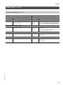
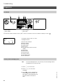
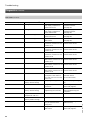
Additional Information
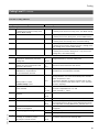
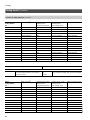
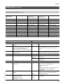
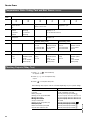
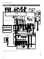
Wiring Diagram
(continued)
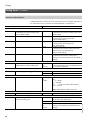
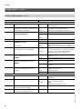
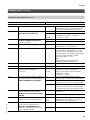
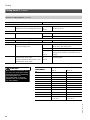
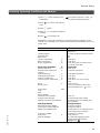
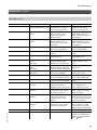
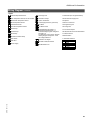
Legend
1
Outside Temperature Sensor
2
Fixed High Limit
A1 Main PCB (GC130 Ignition Module)
Flow Temperature Sensor/Low Loss Header
Fault Alarm Output
A2 Internal Power Supply Unit
3
Boiler Water Temperature Sensor
Ignition Transformer
A3 Optolink
5
DHW Temperature Sensor
Power Supply Accessory (Not Used)
A4 Burner Control Unit
11
Ionization Electrode
Fan Motor
A5 Programming Unit
15
Flue Gas Temperature Sensor
Fan Motor Control
A6 Coding Card
20
Boiler Pump
20A System Pump
21 DHW Pump
28
DHW Re--circulation Pump
Flow Switch
Gas Valve
143 External Blocking Terminals 2--3
External Demand Terminals 1--2
External Heating Program Changeover
Terminals 1--2
The Allocation of the Function ”External
Heating Program Changeover” is Set
Via Coding Address ’91’
144 External 0--10V Signal
KM BUS to PPM/Accessories
Power Supply
A8 LON/Cascade Communication Module
S1 ON/OFF Switch
S2 Reset Button
X.. Electrical Interfaces
BK
WH
G
RD
GY
BN
BL
BLACK
WHITE
GREEN
RED
GREEN/YELLOW
BROWN
BLUE
5418 911 v1.6
Gas Modulation Coil
A7 Connection Adapter
69