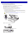
1
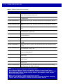
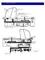
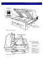
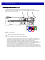
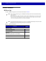
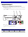
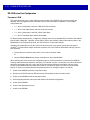
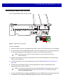
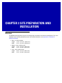
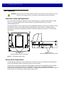
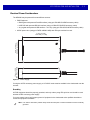
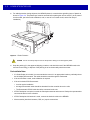
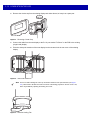
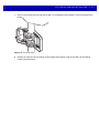
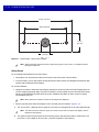
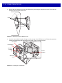
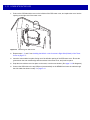
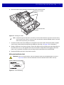
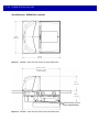
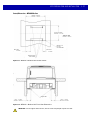
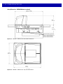
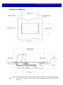
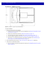
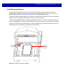
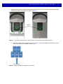
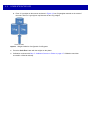
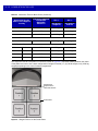
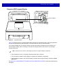
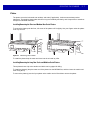
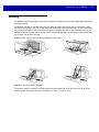
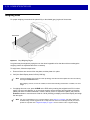
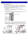
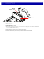
3-4
MP6000 INTEGRATOR GUIDE
Checkstand Preparation
If the MP6000 is not replacing an old bioptic device, and you are installing for the first time into a new
checkstand, verify that the area allows for proper cabling, and an AC/DC power supply. Mounting may require
installation of support(s), leveling screws, and peripheral devices. See Counter Cutout on page 3-5 for more
details about the location and preparation of the opening.
Figure 3-3 Preparing the Checkstand
IMPORTANT The long (20.0 in./50.2 cm) versions are not available with leveling screws. The checkstand should
provide for two leveling screws under the front and rear of the MP6000. The medium (15.7 in./39.9
cm) and short (13.9 in./35.3 cm) MP6000 models have available accessory kits for standard and
long leveling screws.
Liquid Spills and Moisture
Select a checkstand design which allows fluids to flow through, and directs liquids and moisture build up away
from any electronic equipment or storage areas. Should a liquid spill occur, ensure that moisture can flow
through the checkstand without pooling. The power supply should be away from any area where spills may
occur.
Vertical Clearance
For all configurations of the MP6000, the maximum height above the platter is 5.1 in.; the maximum depth
below the platter is 4.08 in.
Tools
No tools are required to install a MP6000 without a scale, or a Checkpoint antenna. The following tools are
required to mount the Scale Display:
• Ruler (or similar measuring device)
• Pencil (or similar measuring device)
• Drill
• 2.4 mm (3/32 in.) diameter drill bit (to make screw holes where display is to be mounted)
• 19 mm (3/4 in.) diameter drill bit (to make cable pass through hole where display is to be mounted)
• #2 Phillips screwdriver.
If the optional leveling screws are used on a small or medium MP6000, a Phillips or flat blade screwdriver is
needed.