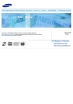
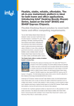
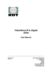
1
d-lab.1
Technical Documentation
_________________________________________________________________________________________
Installation Instruction
d-lab. 1 MPU mother board
Replacement
Version MPU replacement Kit V 2.00 wvs
Page Nr. 1
d-lab.1
Technical Documentation
_________________________________________________________________________________________
Dear valued MiniLab Factory customer. Thank you for purchasing original spare parts. When buying
original spare parts you are entitled to receive help from us and therefore we wrote this document. We are well
aware that this document will be copied and distributed thought out the world, even to the people who are
buying substandard spare parts, but expect to receive the same kind of help. For those who do not purchase
the original spare parts from MiniLab Factory or their authorised dealers, be warned copyright law throughout
out the world prohibits using this document. It can and will be punished to the fullest extend of the law. As well
as you are entitled to receive free replacement license keys for your original purchased licenses. Please see
the enclosed license key unlocking sticker, which has to be send in with your license key replacement request.
This document is intended for technical personal and not the normal d-lab 1 operator or owner. This document
does describe to some extend the replacement of an MPU (gigabyte 1000 Pro) with a Siemens Fujitsu
(D2156-S) motherboard after a mother board crash.
There are many way to accomplish this. There is the direct replacement of the motherboard. As well as the
exchange between the mother boards. This exchange between the mother boards (the IPU become the MPU)
will be more expensive, but it will reduce your down time by at least one day. When exchanging the IPU and
MPU motherboards you will keep your machine data unchanged and therefore will not have to contact MiniLab
Factory for replacement licenses. As well as your machine and product configuration are still in place and can
be used as soon as the machine will boot again.
Note: the above only applies for a motherboard crash not a hard disk crash. If the hard disk crashes a mother
board replacement will not help. You have to replace the hard disk. You will have to load all your data manually.
Over last years it has been common not to back up your d-lab.1 data. If you are one of the lucky once, who did
back up the machine and channel configurations and LCD offset values you are in luck you can skip the first
part of this document.
Hardware modifications:
Mainboard:
Processor:
Memory:
Drive:
NIC:
Serial Board:
Hard disc:
Framegrab.:
Graphic:
Siemens D2156-S Intel D945G ATX board for industrial applications
Intel P IV 3 GHz LGA-775 EMT64 with heat sink and fan
MPU: 2 x 512 MB DIMM DDR2 certified for MB D2156-S
IPU: 2 x 1024 MB DIMM DDR2 certified for MB D2156-S
Samsung SH-S182M DVD-RW/+RW/DVD-RAM/CD-RW
MPU:
1 x LAN (RJ45) 1000BaseT Broadcom BCM5751
1 x Intel network interface card Intel EXPI9300PT
IPU:
1 x LAN (RJ45) 1000BaseT Broadcom BCM5751
1. Moxa C104H 4 COM card incl. quadruple breakout cable
2. Sunix 4056A 4 COM card incl. quadruple breakout cable
MPU: 1 x IBM/Hitachi 3.5", SATA-II 80,0GB
IPU: 2 x IBM/Hitachi 3.5", SATA-II 80,0GB
IPU: mvTITAN-LVDS/A V. 1.00 PCI
MPU: onboard INTEL GMA950
IPU: Asus Extreme AX300SE-X TD PCI-Express
Version MPU replacement Kit V 2.00 wvs
Page Nr. 2
d-lab.1
Technical Documentation
_________________________________________________________________________________________
Recovering your Data :
When keeping the IPU and replacing the MPU
Tools required:
One USB or serial (PS2) mouse, one USB or serial (PS2) keyboard,
One Philips screwdriver, straight screwdriver, side cutter, some cable ties,
Blank CD
1.
2.
3.
4.
5.
6.
7.
8.
9.
10.
11.
12.
13.
14.
15.
16.
17.
18.
19.
20.
21.
22.
23.
24.
25.
26.
27.
28.
29.
Remove the white cover behind the monitor (this will expose the MPU and IPU PC’s)
Remove all cables from both PC`s, by unplugging them or using the screwdrivers to loosen the screws.
Remove now the 6 Phillips screws, which hold the PC, frame in place.
Pull the unit forward, about 2-3 inches. Be carefull do not pull too hard.
Disconnect now the MPU and IPU from the power connections.
Remove the IDE cables from both units, (use the paper tabs to pull on the plug)
Remove the gray plug from the ON / OFF (timer light) switch.
Remove the USB cable from the card reader (File Print option).
Pull out the unit carefully.
Remove the Serial interface and Network card from the MPU motherboard.
Remove the MPU motherboard from the mounting bracket using a Phillips screwdriver.
Remove now the cards from the IPU motherboard. (Note positions).
Mount now the MPU cards (Serial and Network) to the IPU motherboard. Use same positions used on
the MPU.
You should have only two cards on the new IPU PCB.
You have to mount now the IPU UPSIDE down into the MPU position (Card cadge upside down)
Plug now the MPU ATX power (24 pin) cord into the board, the MPU-CPU fan (yellow, black)
connect now the IDE MPU hard disk into the IDE port 1 red the CD ROM into the IDE 2 white port,
Connect the touch screen cable to a USB port
Connect the VGA cable to the VGA port on the motherboard.
Connect the mouse and keyboard to the green and purple port respectively
Reconnect the timer cable to the board behind the ON (timer light) button.
Take now an external PC power cord and plug it into the bottom PC power supply (MPU) connect the
other side to a MAIN wall outlet (If the power supply unit has been replaced in the past make sure that
the local country voltage is select at the power supply. The US use 120 AC and Europe 220 AC. The dlab 1 is using 220 volt AC and an automatic power supply is normally used!)
Find the DB 25 plug on the top (upside down now).
Look for Pin 5 (orange) and 18 (yellow). Only when DB25 plug is connected (cable might be to short
now)
Use a small paper clip and shorten pins 5 and 18. THIS should start up the MPU PC.
You should see the MPU come to live the CD-ROM drive will light up as well as the monitor.
Wait until you see two little girls eating ice cream. Now press the <ALT> and <F12> key a window
should pop up and ask you if you what to disable the Auto Int. function. Press <YES>
now press both <ALT> keys (left and right of the space bar) this will open the watchdog window.
Open up explorer and copy the contents of the below directories to a blank CD using Nero Express.
C:\Program Files\Ahead\Nero\nero.exe
Version MPU replacement Kit V 2.00 wvs
Page Nr. 3
d-lab.1
Technical Documentation
_________________________________________________________________________________________
Directories and Files to be save to CD:
D:\data\index\….
D:\data\combiprints\....
D:\data\ Luts\....... (At least, 4 offset files small, 4 offset files large + one LCD_lut.txt file)
D:\data\Dbbackup\...
D:\data\statistics\...
D:\backup\xxxx.src (channel and machine backup files)
C:\programfiles\agfa\dlabversion\pa\...
C:\programfiles\agfa\dlabversion\pp\...
C:\programfiles\agfa\dlabversion\fp\...
Note:
there is no need for us to copy the licenses keys for your machine. Do to the fact that after
replacing the hard disk they become void. They have to be reordered from MiniLab Factory.
After you have saved the files to the CD, remove the CD and put it into a save place.
We will have to use it later.
Switch now the MPU PC off using the shut down function within windows.
Remove the main power cord from the wall socket and the MPU PC power supply.
To remove the MPU and transfer it back to an IPU:
1.
2.
3.
4.
5.
6.
7.
Remove the MPU PC (ATX) power cable
Remove the four pin connector (yellow \ black)
Remove the two IDE cables (red and white socket)
Remove the grey 10 pin timer card cable
Now you should be able to remove the unit from the holder.
Remove now the two previously installed cards (Network \ Serial Adapter Card)
Reinstall the removed cards from the IPU unit. (Graphics Card (print engine), LVDS, Network Card)
Your IPU is now back to the original settings.
MPU hardware Kit: Part No.: 10+9.8070.9050.0
MPU:
− MB: 1 x D2156S Intel D945G ATX
− CPU: 1 x INTEL P 4 3.0 GHz with heat sink and fan
− RAM: 2 x 512 MB DDR2 PC 533
− HDD: 1 x HI 80 GB 3.5", SATA−II
− ADD: 1 x SATA cable 50 cm
- Cooling fans (3)
Version MPU replacement Kit V 2.00 wvs
Page Nr. 4
d-lab.1
Technical Documentation
_________________________________________________________________________________________
Cooling Fans MPU:
Please see below pictures how to mount the cooling fans. Please make sure that the air blows into the PC (pic
no.3) shown direction. Cool air should be blowing INTO the PC, from the side. Whilile ht air vents at the top. It is
important that we create airflow through the PC. Please note that some machines have already the below
cooling fans installed therefore they do not have to installed. Only the new Siemens / Fujitsu mother board
might require cooling.
Pic 1
Pic 2
pic 3
Version MPU replacement Kit V 2.00 wvs
Page Nr. 5
d-lab.1
Technical Documentation
_________________________________________________________________________________________
Installing the NEW MPU motherboard:
Tools required:
One USB or serial (PS2) mouse, one USB or serial (PS2) keyboard,
Philips screw driver, straight screwdriver, side cutters.
1.
2.
3.
4.
5.
6.
7.
8.
9.
10.
11.
12.
13.
14.
15.
16.
17.
18.
19.
20.
21.
22.
23.
24.
25.
Remove the white cover behind the monitor (this will expose the MPU and IPU PC’s)
Remove all cables from both PC, by unplugging them or using the screwdrivers to loosen the screws.
Remove now the 6 Phillips screws, which hold the PC, frame in place.
Pull now the unit forward, about 2-3 inches. Be careful do not pull too hard.
Disconnect now the MPU and IPU from the power connections.
Remove the IDE cables from both units, (use the paper tabs to pull on the plug)
Remove the grey plug from the ON / OFF (timer light) switch.
Remove the USB cable from the card reader (File Print option).
Pull out the unit carefully.
Remove now the Network card and the Serial interface card.
Disconnect the little green plugs on the bottom left of the MPU motherboard.
They are labelled on the plug (LED power on, HD-Led, PWD on, reset).
You can leave the CPU and memory in place. We will not use them (unless your IPU breaks).
Use now a Phillips screwdriver to remove the motherboard.
Mount now the NEW Siemens motherboard, using the Phillips screwdriver.
Mount now the two DIMM’s (Memory). (Blue sockets, the black once are not used)
Mount now the NEW CPU to its socket by lifting the lever.
Mount now the NEW Cooling fan (you might have to loosen the locking pins first).
Mount now the two PCI cards (Network and Serial).
Mount now the external USB connectors (1 and 2) to the internal USB port.
Connect now the little green plugs to the mother board (power on, HD-Led, PWD on, reset). (see
diagram below)
Remove now the OLD MPU IDE hard disk from the mounting bracket by losening first the black plastic
screw, between the three hard disks.
Exchange now the old IDE hard disk with NEW STA hard disk supplied with the kit.
Connected the red STA cable to the hard disk.
Mounted the NEW hard disk to the machine. Use the black thumbscrew to secure the two hard disks.
Inset now the PC main frame into the guide rail and push it half way in.
Connecting the MPU: All cables are marked MPU
1. Insert the four (4) pin plug (yellow black)
2. Insert the ATX power supply plug (Note the plug is shorter than the socket). You will end up with four
(4) open sockets! Plug uses the lower part of the socket.
3. Plug now the STA (red) hard disk cable into port 1 on the motherboard.
4. Insert the IDE CD drive cable in the blue IDE socket.
5. Insert the USB cable from the optional card reader into the ext. USB port on the motherboard.
Connecting the IPU: All cables are marked IPU
1.
2.
3.
4.
5.
Insert the four (4) pin plug (yellow black)
Insert the ATX power supply plug.
Plug now the first IDE hard disk cable into the red socket on the motherboard.
Insert the second IDE hard disk cable in the white socket on the mother board
Connect now the grey 10-pin timer card cable into its socket behind the on reset switch.
Version MPU replacement Kit V 2.00 wvs
Page Nr. 6
d-lab.1
Technical Documentation
_________________________________________________________________________________________
Diagrams:
MPU mother board / timer card connectors:
(Little green connectors)
MPU mother board connections:
Version MPU replacement Kit V 2.00 wvs
Page Nr. 7
d-lab.1
Technical Documentation
_________________________________________________________________________________________
Errors during a software load.
MPU:
It has been reported that the int. and ext. Network (LAN) card might have the wrong address assigned to it.
Please see in the below software installation instruction, how to set the Network (LAN) address.
It has been reported that some mother boards will not boot. Due to an error in the BIOS settings, the <halt on
keyboard> or <halt on all errors> had been set to on.
IPU:
It has been reported that some mother boards will not boot. Due to an error in the BIOS settings, the <halt on
keyboard> or <halt on all errors> had been set to on.
Hard disk:
A Linux image file load could not be loaded, because one or more files had been set to read only. Therefore reformat the hard disk. To re-format use the MPU PC, you will have to delete the done files again.
Switch off during boot:
If your IPU switches on, but after 15 to 25 sec it switches off. Make sure that you reverse the plug on the
Power on LED socket. The polarity is important on this plug! Most of the time both wires are grey, therefore
we do not know for sure which end is Plus(+) while the other is (-).
BIOS :
It has been reported that an incorrect BIOS setting had been loaded on mother boards. Due to the nature of our
st
business we never know which BIOS we have to load. Please insert the 1 boot CD (MPU disk 1), after the boot
you will see the boot menu. Select the BIOS settings (2) and load the correct mother board BIOS.
Please note: not load the IPU BIOS to the MPU or the MPU settings on the IPU mother board. No harm will
occur, but your system will not boot correctly.
Version MPU replacement Kit V 2.00 wvs
Page Nr. 8
d-lab.1
Technical Documentation
_________________________________________________________________________________________
Installing the d-lab. 1 windows operating system.
The d-lab. 1 installer software comprises of 2 CD-ROMs. The new V 2.02 A installer supports the
current system configuration and is downward compatible.
Booting from CD.
1. Connect a keyboard and a mouse to the MPU PC.To start the installation, use the 1 st CDROM disk. When using a new Siemens motherboard, you can select the boot menu by
pressing the <F12> key where you have to select the CD-ROM as the 1st bootdevice
You might be prompted to enter a password, use “ AGFA “ to enter the boot menu.
2. Booting from the 1st CD.
After a successful boot from the installation CD-ROM, a menu is displayed from which you
can select from the following items:
1. Installation of the operating system
2. Updating of the BIOS and the BIOS settings
3. Cancel installation
3. Installing the operating system (windows 2000).
After selecting menu item.
<1…Windows installation>
Installation is started.
Version MPU replacement Kit V 2.00 wvs
Page Nr. 9
d-lab.1
Technical Documentation
_________________________________________________________________________________________
4. A Ghost system screen is displayed.
Note: You cannot enter any data using the keyboard, until prompted.
The progress bar will not MOVE (blank).
Note: There will be a message displayed, in German approx. 10 minutes later, which will
prompt you (in German) to insert the 2nd CD-ROM disk.
5. Insert now the second installation disk and confirm the message by using the <Enter> key,
the installation will continue.
After the completion of the installation of the 2nd installation disk, the system will automatically
restart.
6. Windows will restart. Windows will now run some script files and detect all new hardware and
will install the required drivers.
After completion of the set up phase, the system will restart and reboot into the
d-lab 1 desktop screen.
7. Check the TCP/IP setting of each Network card!
LAN int.
(Single Network Card)
(Example, Intel(R) Pro/1000 MT Desktop.)
TCP/IP settings:
Subnet mask:
192.168.64.1
255.255.255.0
Lan Ext.
(On board Network Card)
(Example, Broadcom Nexttreme Gigabit.)
TCP/IP settings:
Subnet mask:
192.168.1.10
255.255.255.0
Confirm any changes with “YES” you want to overwrite any existing adapter.It has been noticed that
wrong IP addresses have been assigned to the installed network cards, which then will cause the
IPU not load.
Version MPU replacement Kit V 2.00 wvs
Page Nr. 10
d-lab.1
Technical Documentation
_________________________________________________________________________________________
Installing the d-lab. 1 main software
(From V10.00 C to V 10.00 G)
1.
2.
3.
4.
5.
6.
7.
8.
9.
10.
11.
12.
13.
14.
15.
16.
17.
Insert your main d-lab. 1 software into the CD-ROM drive.
Select now the <run> command via the start menu.
Use the browse function
Look for the CD-ROM drives normally (E:\..)
go to E:\version\MainSW\install\DLAB1_10.00(C to G)_setup8\setup.exe
Click on <open>
Click now on <okay>
This will now start the installation process.
Click on <Next>, then on <Next>, make sure that release is checked, then on <Next>
make sure that dlab PC is checked Click on <Next>
When asked do you what to copy the firmware click on <YES>
make sure that DB Install is selected in the radio button Click on <Next>
You should see now the programs, which will be downloaded. Click on <Next>
You will see now a progress bar loading the software.
A windows window will be displayed requesting you to restart the PC, Click on <Finish>
The d-lab.1 PC will shut off and restart.
The program will stop at the Windows desktop. Click now on the <Yellow U-turn> sign.
After pressing the yellow U-turn sign the main software will be loaded. Again you will see some scripts running.
Like the SCM card reader will be detected (if installed). You will see the two little girls with the ice cream screen
again. You will notice the
+++++ connecting to image PC ++++++
You might have to wait for up 30 min before you see another screen. If you used a different main Software it is
necessary for the Image PC (IPU) to be reloaded from scratch and this can take a little time. So be pertained
and let the machine does its magic.
After the Image is up and running you might see some firmware downloads again wait until the
d-lab.1 has finished the software downloads.
At the end you will be rewarded with the normal AGFA GUI interface.
Now take your safely stored back up CD-ROM and load the machine data and the configuration files.
Call up the service screen:
Note: You will have to import the Index layout files via the explorer window. The same applies for the Lut files
and the combi print layout files.
1.
2.
3.
4.
5.
load the index print layouts from your back up CD to the index folder on D:\data\index
load the combi print layouts from your back up CD to the combiprint folder on D:\data\combiprint
Copy now the all the LUT files (9) from your backup CD to the Luts folder on D:\data\luts
Copy the same (9) files to the D:\sv_in_dir folder.
Copy one more time the same (9) files to C:\d-lab.1\%current version%\export_mainPC\Luts folder.
Windows will ask you if you want to over write some files, confirm with <YES>.
6. Close now the service GUI.
Version MPU replacement Kit V 2.00 wvs
Page Nr. 11
d-lab.1
Technical Documentation
_________________________________________________________________________________________
Loading the machine and product configurations:
Note: your backup CD-ROM is still in the CD-ROM drive. We will now recover the old machine data as well as
your old print channel data. If you know how to do it you can skip this part, if not please follow the steps below.
Remember a machine back should always be done when you have made a major change. Therefore we
recommend doing a back up at least once a month. You should alternate between a CD-ROM and the local PC
backup.
Reloading your settings:
1.
2.
3.
4.
5.
6.
7.
8.
9.
click on <settings>
click on <load settings>
check the <machine settings> and <Product config> button
Click on the <CD icon> on the left. Your back up data will be displayed within the backup window.
click now on the last know good back up.(selection will be high lighted)
click now on <load>
confirm the over write with <YES> this will prompt an info screen (settings being loaded)
you will have to confirm the next info screen with <OK>
The machine should automatically restart. If not press the <ON Reset> button behind the monitor
Your print channels and all your machine setting should be loaded. You should be able to use your machine
with film in standard mode, reorder, and networking mode.
If you use an image box or other programs which communicate with the d-lab.1, you will have to configure the
Network settings under <settings>, <machine settings>, and <network settings>. If you need help please
contact one of our service departments throughout out the world.
License keys reissued:
Note: due to the fact that we had to replace the hard disk, all of your license keys became void and therefore
have to be reissued. Please use the enclosed form and send it either via fax or e-mail to our head quarters in
Germany. We will be glad to reissue the license key, which you already have purchased in the past. This is
another reason why to purchase genuine spares from us.
We hope that this document was helpful. If you have a questions or comments please feel free to share them
with us.
Your,
Technical service team
Version MPU replacement Kit V 2.00 wvs
Page Nr. 12
d-lab.1
Technical Documentation
_________________________________________________________________________________________
License Key Request
Note:
When purchasing original spare parts from MiniLab Factory or there authorized distributors your are initialed to receive
your previously purchased license keys for free. If you are not using original spare parts from MiniLab Factory you will
not have receive the special parts seal. Therefore we reserve the right to charge a handling fee for your replacement
license keys. We believe that you will understand that only original spare parts will unsure that your machine will work in
its designed specifications.
Lab Name:
____________________________________
Address:
____________________________________
City:
____________________________________
Country:
____________________________________
Return Fax No.:
____________________________________
Machine ID: ____________________________________
Machine FN: ___________
Model:
d-lab. 1
Standard license keys (US only)
□
d-lab. 2 or 3
□
Check here
□
□
Index import
Combi / Passport
Optional license keys:
FilmonCD_ON_board
Fileprint_on_board
(d.lab 1 only)
(d-lab 1 only)
Scratch_corr_slide
Slide_Film_unmounted
Click_rate_enable
Red_eye_correction
□
□
□
□
□
□
Manufacture seal sticker (part of the original CPU kit)
Without this sticker we reserve the right to charge a
handling fee for issuing the license keys.
Version MPU replacement Kit V 2.00 wvs
Put sticker here:
Page Nr. 13