1
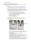
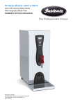
AUTO-FILL
WATER BOILERS
INSTRUCTION MANUAL
MODELS COVERED
WB3
WB7
WB15
WB5E
1
IMPORTANT HEALTH AND SAFETY INFORMATION
PLEASE READ BEFORE USING YOUR NEW WATER BOILER
Your new water boiler is designed to provide a constant source of near boiling
water for the preparation of hot drinks. THIS IS VERY HOT
All personnel must be provided with sufficient and appropriate training in the
safe use of this appliance.
An instruction sheet displayed next to the machine is often helpful in notifying
users that the appliance contains and dispense near-boiling water.
In line with Health & Safety requirements we recommend that a risk assessment
be carried out after the boiler has been installed.
It is advisable to display a sign informing customers that drinks made from this
boiler are very hot.
During normal use of the boiler, certain surfaces will become hot. (especially
near to the draw off tap). Care should be taken to avoid potential injury from
burns and scalding whilst operating the appliance.
Disclaimer. This appliance is designed to heat water. No other medium should
be used. Glen Dimplex UK Ltd will not be held responsible for any accidents or
injuries that occur from either misuse of the appliance or temperature of water
or the hot drinks served.
2
INTRODUCTION
Your new water boiler is designed to give years of trouble free service provided
that the instructions contained in this manual are followed carefully.
Your new boiler is energy efficient, simple to operate and easy to service.
It is recommended that the installation is carried out by a properly qualified fitter.
CHECK LIST
Before starting installation, check that you have the following parts:
1.
2.
3.
4.
5.
Boiler Unit
Case
Mounting Template
Fitting Kit
Tap Kit (WB5E Only)
INSTALLATION
POSITIONING THE UNIT
The heater should be positioned in a convenient place on a wall that is capable
of supporting it safely. Use the mounting template and fitting kit provided.
Position the boiler so that the tap is about 400mm above a draining board.
Leave sufficient space around the unit to enable access for servicing, paying
particular attention to the position of the top centre fixing screw that holds the
cover in place.
Screw in the top two screws leaving about 6mm protruding and hang the
machine using the keyhole slots provided. Once the machine is positioned,
tighten the top screws and insert the bottom screw.
ELECTRICAL CONNECTION ALL MACHINES
Supply – 220/240V 50Hz – 3kW. The circuit should be protected by its own
13amp double pole connection unit with flex outlet to BS5733, alternatively the
circuit should have means of disconnection incorporated in fixed wiring, having
a contact separation of at least 3mm in all poles. Minimum cable size is 1.5mm2.
The use of an ELCB is recommended.
Electrical installation should conform to current I.E.E. wiring regulations.
When using fixed wiring, the bare section of earth wire must be sleeved to
within 8mm of the end.
Only a qualified electrician should carry out this work.
3
WARNING: THIS APPLIANCE MUST BE EARTHED
REAR ENTRY OF CABLE
Fixed or flexible cable to be connected direct to the terminal block, cable gland
not utilised.
BOTTOM ENTRY OF CABLE
Use the cable gland. Loosen cable-gripping nut. Pass cable through gland,
leaving enough free cable to connect into the terminal block. Tighten cable
gland grip nut.
DO NOT SWITCH ON UNTIL THE INSTALLATION IS COMPLETE AND THE CASE AND
TAP ARE IN PLACE
WATER CONNECTION
NOTE: Although it will not harm the boiler, it should not be operated with
the water supply turned off.
The water supply must have a pressure not exceeding 7 Bar (700kpa) and no
lower than 1 Bar (200kpa). If the mains water pressure is below1 Bar a fault
situation could arise as described in section; “Temperature Control and
Safety cut-outs”.In addition the water inlet valve may not seat properly
and can cause overflowing
If your water pressure exceeds 7 Bar, a suitable pressure reduction valve will
need to be fitted to the water supply to bring it to a level that the machine can
cope with. Failure to do this could result in the boiler overfilling .
The manufacturers cannot be held responsible for any machine malfunction if
the water pressure exceeds that stated. If in doubt, consult your water supply
company.
The boiler has a type B air gap in compliance with water bylaws and has both
WRAS and KIWA approval.
Please note that washing machine hoses are not suitable for drinking
water and will cause a very bad taste to the water.
A 15mm stop valve should be fitted between the water supply and the boiler so
that the machine can be isolated. Water purification filters are available to
ensure fresh tasting water. Please contact the service department for details on
01704 502911. In hard water areas scale can cause problems. Fitting a scale
reducer will help minimise scale.
We regret that the manufacturers cannot be held responsible for scale problems
even if a scale reducer has been installed.
4
BOTTOM ENTRY
Connect to a suitable cold drinking water supply using 15mm copper pipe and
push on the ‘T’ piece supplied. The ‘T’ has been blanked off using a brass plug.
Leave this plug in place. Push the ‘T’ piece firmly onto the water inlet solenoid
pipe with the brass plug facing forward. Then push the 15mm cold water supply
firmly into the bottom of the fitting.
To avoid damage to the unit, do not use any solder connections whilst pipes are
connected to the boiler.
REAR ENTRY
For rear entry of cold water supply, remove the plug from the ‘T’ piece by
compressing the grey collar and pulling out. Push the plug firmly into the bottom
of the ‘T’ piece.
Push the ‘T’ piece firmly into the water inlet solenoid pipe with the ‘T’ facing the
wall.
Push the 15mm cold water supply firmly into the ‘T’ fitting.
To avoid damage to the unit, do not use any solder connections whilst pipes are
connected to the boiler.
OVERFLOW PIPE BOTTOM ENTRY
In your fitting kit you will find a straight push on connector with a small length of
15mm copper tube pushed into it.
This connector must be pushed onto the corresponding overflow pipe on the
bracket (alongside the solenoid).
If you wish to extend the overflow, remove the copper pipe supplied and replace
with pipe of your chosen length. The pipe must have a continuous fall and
should not be longer than 200mm (if a longer run is required use 22mm pipe to
avoid airlocks). The overflow pipe should have no more than four right angle
bends and should discharge to a safe visible position.
Under certain conditions, the overflow pipe could vent steam, hot water or cold
water and the manufacturers cannot be held responsible should damage arise
from such discharge if the overflow pipe has not been directed to a suitable
position where overflowing water can run away safely.
Under no circumstances should the overflow pipe be allowed to vent
inside the case of the boiler.
5
OVERFLOW PIPE REAR ENTRY
In your fitting kit you will find a straight push on connector with a small length of
15mm copper tube pushed into it.
If rear entry has been chosen this connector must be replaced by a push on
elbow (available from plumber’s merchants). Push the elbow onto the overflow
pipe on the bracket (alongside the solenoid).
The pipe must have a continuous fall and should not be longer than 200mm (if a
longer run is required use 22mm pipe to avoid airlocks). The overflow pipe
should have no more than four right angle bends and should discharge to a safe
visible position.
Under certain conditions, the overflow pipe could vent steam, hot water or cold
water and the manufacturers cannot be held responsible should damage arise
from such discharge if the overflow pipe has not been directed to a suitable
position where overflowing water can run away safely.
Under no circumstances should the overflow pipe be allowed to vent
inside the case of the boiler.
VENT PIPE
A small silicone tube connects the boiler to the wall bracket. Ensure that this is
connected and that the opening in the bracket is not obstructed.
FIT CASE
Attach the L.E.D display lead to the case per the instructions. Using the fixing
screws fit the outer case to the boiler.
WB5E ONLY. FIT TAP
Remove plastic plug from the tap boss. Ensure that the yellow washer is in
place and carefully screw the chromed tap extension into place using a 28mm
open-ended spanner to tighten. Do not use grips or tools that are likely to
scratch the chrome.
Push the grey tap collar firmly into place and twist to fit snugly against the case.
6
OPERATION (All models except WB5E)
After the electrical and water connections have been made, switch the power
and water supply on.
The power and ready lights will flash once. The power light will then be
constantly illuminated to indicate mains supply.
Providing the water supply is present, the machine will start to fill. If the machine
does not fill to its pre-set level within 4 to 5 minutes the red service light will
flash 6 times. If this happens, check that the water stop valve is turned on. If the
valve is on, check that the small plastic filter in the water inlet solenoid on the
machine is not clogged with debris. To clear the service light, switch the
machine off and then back on again.
When the correct temperature has been reached, the ready light will be
illuminated, wait at least 10 minutes after the ready light illuminates before
starting to draw water (on first installation only). Your machine does not fill
completely at once. The water input is electronically controlled to obtain
maximum output, temperature and efficiency.
In daily use, switch on and wait for the ready light to illuminate. The water will
then be at the correct temperature and the boiler ready to use. We recommend
that you switch the power supply to the boiler off overnight and when the unit is
not in use.
7
OPERATION (WB5Eonly)
After the electrical and water connections have been made, switch the power
and water supply on.
When the power supply is switched on, the small indicator lamp on the front
panel will glow orange. This means that the water is filling to the bottom probe.
When the bottom probe has been reached, the indicator lamp will change to red
to show heating. When the water has reached the correct temperature the light
will change green. Wait a further 10 minutes before starting to use.
Your machine does not fill completely at once. The water input is electronically
controlled to obtain maximum output, temperature and efficiency.
In daily use, switch on and wait for the green light. The water will then be at the
correct temperature and the boiler ready to use.
TEMPERATURE CONTROL & SAFETY CUT OUT
A small knob protrudes from the base of the mounting bracket (Not WB5E). This
controls the boiler temperature. It has been factory set at approximately 98oC
and should not need adjustment. However, under certain conditions (extreme
change in ambient room or cold water temperature), the boiler temperature may
fluctuate slightly. The knob may then be used to adjust this. Using a
screwdriver, loosen the transit bracket, which holds the knob in place. Turn the
knob clockwise to increase or anti-clockwise to decrease the temperature.
All models except WB5E
Should the temperature be set too high, steam or boiling water will discharge
through the overflow pipe. In the event of this happening, a high temperature
control switch will switch off the heater. The red service light will flash 10 or 12
times depending upon the water level. Switch the boiler off at the electricity
supply and switch back on a few moments later. This will reset the boiler but if it
cuts out again it is recommended that you then adjust the temperature by
turning the knob anti-clockwise. If the boiler continues to over-boil, contact the
Instanta service department on 01704 502911 for advice.
WB5E
Should the temperature be set too high, steam or boiling water will discharge
through the overflow pipe. In the event of this happening, a high temperature
control switch will switch off the heater. After a short period, the neon indicator
will change from green to flashing red or flashing red and green. Switch the
boiler off at the electricity supply and switch back on a few moments later. This
will reset the boiler but if it cuts out again it is recommended that you contact
the Instanta service department for advice.
CLEANING
The external surface of the machine can be kept clean by wiping with a damp
cloth.
Do not use abrasive material on the outer surface of the machine.
8
TECHNICAL SPECIFICATION ALL MODELS
Tank constructed in stainless steel.
Tank insulated from outer casing with high temperature polystyrene.
All boilers have electronic control of the main functions. This means that the
temperature is controlled precisely within given parameters. The circuit
constantly monitors the operation of the machine and warns the user via the
light if abnormal circumstances have been detected.
If the light flashes, refer to the diagnosis codes.
MAINTENANCE
NOTE: After initial commissioning or subsequent re-commissioning
(service-repair), check that the water supply has been established prior to
switching on the boiler.
The boiler should be periodically checked for scale build up. The frequency
depends upon hardness of the water and whether or not an effective scale
reducer is fitted. It is advisable to keep a spare tap spring (part no TP1007/L)
and washer (part no TP1001/L) in case of emergencies. Apart from the removal
of scale, no regular maintenance should be required.
9
DE-SCALING All models except WB5E
To de-scale your machine, first disconnect the machine from the power supply.
Remove the case by removing the top and bottom screws holding the case to
the wall bracket.
Drain the remaining water through the drain plug in the bottom of the tank.
Remove the boiler lid by unscrewing the fixing screws. The tank is now
accessible.
The whole boiler can be disconnected and lifted away from the wall fixing by
removing the push on water and vent fittings and disconnecting the electrical
components. However, it is recommended that only a qualified person
undertakes this work and that unless a qualified person is available, the descaling is carried out with the boiler on the wall.
Lift out the baffle plates on the inside of the tank (taking note of the position of
the plates). Remove as much scale as possible by hand. Dissolve any scale
that is difficult to remove by using a de-scaling solution. Remember to replace
the drain plug before using the de-scaler.
Clean the level sensing probes and their white holders completely using a clean
non-metallic scourer.
Ensure all traces of de-scaler are removed before using the boiler again.
Rather than frequently de-scaling the machine, it may be preferable to install an
effective scale reducer or WRAS approved food quality water softener. This will
reduce the frequency of de-scaling but will not remove scale completely in some
areas.
DE-SCALING WB5E
To de-scale your machine, first disconnect the machine from the power supply.
Drain all the water using the tap. Disconnect the tap. Remove the case by
removing the top and bottom screws holding the case to the wall bracket.
Drain the remaining water through the drain plug in the bottom of the tank.
Remove the boiler lid by unscrewing the fixing screws. The tank is now
accessible.
The whole boiler can be disconnected and lifted away from the wall fixing by
removing the push on water and vent fittings and disconnecting the electrical
components. However, it is recommended that only a qualified person
undertakes this work and that unless a qualified person is available, the descaling is carried out with the boiler on the wall.
Lift out the baffle plates on the inside of the tank (taking note of the position of
the plates). Remove as much scale as possible by hand. Dissolve any scale
that is difficult to remove by using a de-scaling solution. Remember to replace
the drain plug before using the de-scaler.
10
Clean the level sensing probes and their white holders completely using a clean
non-metallic scourer.
Ensure all traces of de-scaler are removed before using the boiler again.
Rather than frequently de-scaling the machine, it may be preferable to install an
effective scale reducer or WRC approved food quality water softener. This will
reduce the frequency of de-scaling but will not remove scale completely in some
areas
SERVICE WARNING LIGHT (WB5E only)
Your boiler is able to detect certain fault conditions, these are as follows:
1.
Flashing Green
=
The bottom probe is scaled up.
2.
Flashing Orange
=
The water supply is turned off or the
bottom probe is scaled up
3.
Flashing Red
=
An internal component has failed or.
The safety cut out has come into
operation
4.
Flashing Green & Red
=
As Above.
11
SERVICE WARNING LIGHT (All Models except WB5E)
All models except WB5E have this facility. This light is designed to help you
discover the cause of any malfunction. If the circuit senses a problem, the
service light will flash a number of times and then pause and repeat this
sequence. Count the number of flashes between pauses and refer to the table
on the back cover. Some serious service problems will disable the boiler whist
less serious ones will allow you to continue to operate until a convenient time
arises for the fault to be rectified.
NUMBER OF
FLASHES
BETWEEN
PAUSES
1 Constant
2
3
4
5
6
7
8 or 9
MEANING
ACTION
Water level sensor has scaled up
at normal level and machine has
filled to a higher level
Operating level sensor has been
detected but lower level sensor
has not
Overfill level sensor has been
detected but other sensors have
not
Danger level sensor has been
detected and machine functions
have been shut down
Thermistor or potentiometer have
failed
Boiler has failed to fill in the
allotted time. Possible causes :1. Water supply turned off.
2. Water inlet valve has failed.
3. Blockage in water inlet pipe.
4. Pipe connecting inlet valve to
boiler has become detached.
5. Bottom sensor is scaled up
The temperature sensor
(thermistor) has become
disconnected or the heating
element(s) have failed.
Fault on temperature sensor
(thermistor).
10
Heating element(s) faulty .
11
The water supply has been
interrupted and the level has
12
Clean Sensing Probes
Clean Sensing Probes
Clean Sensing Probes
Clean Sensing Probes
Call service department on
01704 502911
Quoting the Serial Number
Check water supply
If in order call Instanta
service department quoting
the Serial Number
Call service department on
01704 502911
Quoting the Serial Number
Call service department on
01704 502911
Quoting the Serial Number
Call service department on
01704 502911
Quoting the Serial Number
Check water supply
fallen to a point at which the
heating element(s) could be
damaged.
12
If in order call service
department on 01704
502911
Quoting the Serial Number
The machine has over-boiled and Call service department on
the level has fallen to a point at
01704 502911
which the element(s) could be
Quoting the Serial Number
damaged. Or safety cut out has
come into operation see
paragraphs re Temperature
Control
13