1
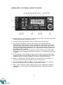
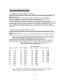
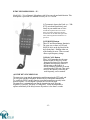
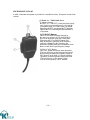
Introduction
Congratulations! Now you are the owner of the most advanced state—of the—art VHF FM transceiver available
today.
Please read this manual carefully before attempting to operate your PCS—6000 transceiver. This will ensure that you
obtain the maximum operating convenience and versatility.
Unpack your PCS—6000 carefully and make sure that it is supplied with the standard accessories listed at page 14. Be
sure to send in the warranty card. Notify the carrier immediately if there is any evidence of damage to the unit. Keep
the
original packing materials in the unlikely event it becomes necessary to return the PCS—6000 for servicing.
CONT N NT S
Cautions Before Operation
2
Major Features
3
Operating Controls and Functions
4
How to use Keyboard
6
How to Store Frequencies in Memory
8
Recalling Memory Channels
10
Memory Seining/Band Scanning
11
Scanning Stop
12
Priority
12
Microphone
13
Accessories List
15
Specifications
16
—1—
CAUTION BEFORE OPERATION 1.
2.
3.
4.
Before connecting the unit to a power supply, make sure that you have the polarity correct. The
red lead of the
power cord should go to the positive (+) terminal of the power supply or battery.
In mobile installations, the system must normally ~e negative—ground. That is, the negative
terminal of the battery should be connected to the automobile chassis. Host modern cars and
trucks are negatively grounded, but a few use positive grounding. In this case, the 005—6000
and antenna must ~e insulated from the vehicle chassis or a short circuit will occur.
5.
The rated supply voltage of this unit is 13.8VDC ± 151. So, be sure that the power supply voltage is 12 to 14
volts. Voltages less than ll.7VOC or greater than l5.9VDC will cause improper operation and possible
damage
to the unit.
3.
4.
5.
Be sure that the antenna is securely mounted on your car and also check the external antenna system for
short—circuit using an ohmmeter and then, firmly screw the antenna plug into the antenna connector 00 the
rear panel of the unit, ho sure to use a 50—ohm impedance cable.
4.
Be sure that the unit is properly located.
When installing it, be sure that it is not placed in a location where it will be exposed to direct sunlight for
prolonged
periods. Also keep the unit wail away from heater outlets.
After parking for long periods in hot weather, the P05—6000 should not be used for transmitting until the
vehicle
interior has cooled down.
-
2–
MAJOR FEATURES
1. C—MOS Microcomputer Control
The built—in microcomputer employs the latest in CMOS technology, to provide you
with unprecedented operating features. This microcomputer controls all of the
scanning, channel selection, offset frequencies ,sub—audible tone operation and
display functions. The lithium battery ensures that microcomputer information is
stored even when power is removed.
2. Unprecedented Wide Frequency Coverage
The PCS—6000 receives 118.000 to 173.995MHz aircraft AM and FM and transmits
140.100 to 149.995MHz. Modifiable to all MARS and CAP frequencies (Proof of
authorization/license required)
3. AM Air Band Receiver Capability
The unit receives the AM band of 118.000 to 135.99Mhz.
4. 20—Channel Memory in The unit receives AM band of 118.000 to 135.995MHz.
Two Banks plus 1 Temporary Channel
Two memory banks, A and B have 10 memory channels each. The memories store
frequency, shift width, offset information, and sub—audible tone frequency as
programmed. An extra memory channel (that we call TM — Temporary Memory) is
provided to allow you to store
any operating condition right at once.
5. Versatile Scanning Functions
Dual memory scan, programmable band scanning , hold scan and delay scan
functions are provided. The operations are detailed in the keyboard operation.
6. Priority Channel Monitoring
Memory channel AD (the first channel in memory bank A) is monitored at every
four seconds regardless of any operating condition. When a signal is received, a
beep will be heard twice.
7. Programmable Frequency Steps
In memory, frequency steps can be set at 5kHz to 20kHz increments of 5kHz.
(European version programmable at 12.5kHz to 50kHz in increments of 12.5kHz.)
8. Built—in Programmable Tone Encoder
57 different tones are built in and tone frequencies can be programmed into each memory
channel.
9. Feather—touch Tuning Control Keyboard
The LED back lighted light touch keyboard performs all tuning operations simply by pushing
the key(s) and key actuation is audibly verified.
10. Large LCD (Liquid Crystal Display)
The LCD shows the operating frequency, S/RF , memory channel in use and various other
operating functions. The LCD is back—lighted by green LEDs, making it possible for you to
read the display even in total darkness.
11. Azden Traditional Discriminator Scan Centering
—3—
-OPERATING CONTROLS AND FUNCTIONS –
(1) Power Switch: Push ‘ON’ Push ‘OFF’ switch. Pressing the button once will turn the power
ON and pressing it again will turn the power off.
(2) Volume Control: Turning the knob clockwise will increase the sound volume.
(3) Tone Squelch (TSQ)/Squelch Control. This control is used to eliminate annoying
background noise when no signal is present. To adjust the control properly for reception,
first turn the knob counterclockwise until background noise is heard. Then rotate it slowly
clockwise until background just disappears. Leave the knob at this position for normal use.
If the squelch control is turned further clockwise, stronger signals will be required to open
the squelch and allow reception.
When the knob is set to the “T.SQ” position, the squelch will open only for signals that
accompany a certain designated sub audible tone frequency. (An optional tone squelch unit
is required)
(4) Keyboard Switches: The keyboard switches are used to select various operation modes
programmed inside the microcomputer. All the keys are LED illuminated for easy location
in darkness. Refer to ‘Details of Keyboard” for each key operation and function.
(5) Minus (—) Shift Indicator: When the indicator is lit, transmission occurs at a frequency
below the receiving frequency, according to the preset value of shift.
(6) Plus (+) Shift Indicator: When the indicator (+) is lit, transmission occurs at a frequency
above the receiving frequency, according to the preset value of shift.
(7) Duplex (“DUP”) Indicator: When the indicator (DUP) is lit in calling memory channel, it
means that the receiving frequency and transmitting frequency is differently set up from
each other.
—4----
(8) Reverse Mode Indicator (REV): This indicator is lit when the reverse operation mode is in
use. (See: Reverse mode operation Page 7)
(9) Low Power Indicator (LOW): When the transmitter output is set at low power (5W—
PCS—6000/IOW—PCS—6000H), this indicator comes on. In the high power mode (25W
— PCS60OO/45W — PCS—6000H), this indicator is not lit.
(10)Signal Indicator (S/RE): This indicator shows the relative incoming signal strength in the
receive mode, and the relative transmitter output power in the transmit mode. (Note: Even
in high power transmit mode, it is possible that not all of the indicators will come on. This
may happen if the antenna SWR is high.)
(11)Hold Indicator (HOLD): This indicator tells you that scanning is in the HOLD mode. In
this scan mode, scanning will stop at any occupied channel and will resume in either about
3 seconds or 6 seconds after the signal disappears. If the~ HOLD scan is not lit, the unit is
in the DELAY scan mode. In this mode, scanning will stop at any occupied channel and
then resume after 6 seconds irrespective of signal condition. For the HOLD mode and
DELAY mode switchover, refer to “How To Program
(12)Transmit Indicator (TX): This indicator lights up when the PTT switch is depressed,
indicating that the unit is in the transmit mode.
(13)Priority Indicator (PRI): This indicator lights up to tell you that the unit is in the priority
mode. (See Priority at page 12
(14)Frequency Indicator
(15)Tone Indicator (TONE): This indicator lights up to tell you that either tone encoder or tone
decoder i5 activated for use with an optional tone decoder when built in or both tone
encoder and decoder are made activated. More specifically, see the table below as regards
the ‘TONE’ indicator vs. tone encoder/decoder, keyboard tone switch and tone squelch
switch.
TONE
Encoder
x
x
o
o
o: pro—programmed—in
Decoder
x
o
x
o
‘TONE’ Indicator
Tone Switch
T.SQ Switch
x
x
x
x
o
x
o
o
o=Switch ‘On’
(16)Busy Indicator (BUSY): This indicator lights up when the unit is receiving signals over
squelch threshold level, indicating that a channel is in use.
(17) Memory Address Indicator: This unit has two memory banks, A and B, each of which has
ten (l0) memories, indicating the memory address in use by 0ch to 9ch.
(18)Memory Bank Indicator: When memory bank A is selected, this indicator shows A and
when bank B is selected, this indicates B. When both A and B are indicated, the blinking
bank is selected, connecting A and B banks in series and enabling you to call 20 channel
frequencies continuously and or scan 20 channels.
—5—
(19)Memory Mode Indicator (M Mode): This indicator lights up when the PCS—6000 is in the
memory mode. In this mode, the up/down keys function as memory address keys, and the
scan key as memory scan key. When the indicator is not lit, the unit is in the up/down
mode.
(20)Function Indicator (F): This indicator will light up when the ‘F’ key (function key) is
depressed, allowing each key to operate as indicated on each keytop.
(21)Control Microphone Connector: This is used to connect the control microphone supplied
with the unit. For details of the microphone, refer to page 13
— How To Use Keyboard —
1. Setting Frequencies: Before attempting to set frequencies, check to see whether or not the
unit is in the memory mode (M MODE lit or not). If M MODE is lit, press the M MODE
key once to release the memory mode and return to up/down mode. You can set or change
frequencies by the UP and or DOWN keys.
When the UP key is pushed once, the operating frequency is moved up by
5kHz, and when the DOWN key is pressed, the frequency is moved down by
5kHz. Channel frequency step is variable to 10kHz, 15kHz and or 20kHz by
following the program procedure given at page 9
2.
Rapid Channel Change.. .(UP, DOWN): The frequency is automatically changed up or
down by holding down the UP or the DOWN key for more than about a second. As the
desired frequency is approached, release the key and then push the UP or DOWN key
repeatedly until the desired frequency is obtained.
3. MHz unit Change: When the function key ‘F’ is pressed and Function Indicator F(2O) is
indicated, pressing either the UP key or DOWN key once will move up or down the
operating frequency by 1MHz.
Note:
1) The ‘F’ indicator is released by any of the key operation other than MHz
Frequency Change and Shift Direction Change procedures.
2) The ‘F’ indicator is automatically released in about 3 seconds unless other key is
pressed after the ‘F’ is pushed.
3) The ‘F’ indicator is released by pressing the ‘F’ key.
4.
Transmit Output Change: Press the ‘F’ key to light up the “F” indicator.
Then press the ‘H/L’ key to select the high power output 25W/45W(PCS—6000/
PCS—6000H) and or the low power output 5W/lOW (6000/6000H). The Low Power
Indicator (9) comes on when the transmit output is set at low power.
—6—
5. Setting Shift Width and Direction: When ‘F’ indicator comes on after the ‘F’ ‘~witch
pressed, pressing the ‘SHIFT’ key will indicate +(6) that means transmission occurs at
6UOkHz above the receiving frequency. Furthermore, when the ‘F’ indicator on, pressing
the ‘SHIFT’ key will indicate —(5) that mean’; ‘transmission occurs at 600kHz below the
receiving frequency.
The plus and minus shift is not activated in the M. (Memory) Mode.
Shift with other than 600Hz can he programmed to any optional
value. Refer to ‘How To Program’ at page 9
Note: When the M Mode indicator is lit, shift key operation is disabled.
6
Reverse Mode Operation (REV)’ When the ‘REV’ key is pressed and ‘REV’ indicated on
the display during repeater operation, the transmit and
receive frequency’s are reversed. To disable the reverse mode operation, push the RF:V
key again and the RFV indicator is turned off to indicate that the reverse mode is disabled.
7. How to operate Tone: When ‘F’ indicator is lit (after the ‘F’ switch is pushed) pressing
the TONE
key will activate tone encoder and the ‘TONE’ indicated on the display.
Repeating the same procedure will turn the TONE off and the TONE indicator comes off.
Note : 1 ) The tone key operation is disabled when tone code( s ) are not programmed in
the computer.
2) Refer to ‘How To Program’ for tone code programming.
3) The tone function is automatically activated when the tone code is pre—
programmed in memory channel.
4) Use the ‘TONE’ key to disable tone operation.
-7-
How To Store Frequencies in Memory:
—Setting Receive Frequency and Tone Code Entry —
a) Pressing the function (F) key and the program (PROG) key will set the unit in the program mode
and the ‘AD’ blinks and indicates that you can write frequency in the MAO (memory bank A,
address channel 0).
b) Select the memory address desired from among 0 through 9 by the UP or DOWN key.
c) Press the M MODE key and you will see that the receiving frequency display flickers.
d) Select a frequency to be stored by using the UP, DOWN, and F keys.
e) Push the M MODE key and then the frequency will be stored in the specified memory.
f) — Sub—audible Tone Code Entry—: After the e) procedure above, you will see that the TONE
indicator flickers for tone code entry. Tone code can be selected by the UP/DOWN key. Tone code
entry is completed by pressing the M MODE key. (An optional tone squelch unit is required).
Note: When the unit is provided with an optional tone squelch unit, refer to the tone squelch unit
code table.
—Setting Transmit Frequency and Tone Code Entry —
a) After the above tone code entry completion, you will see that the transmit indicator (TX) and
transmit frequency flicker. In this case, the frequency displayed is the same as that of the receiving
frequency.
b) Just push the M MODE key when you want both the transmit and receive frequency to be the
same.
But if you want to set a different transmit frequency from the receive frequency, select the
desired transmit frequency by using the UP, DOWN, and ‘F’ key and then press the M
MODE key to complete the transmit frequency entry in the memory.
c) You will see then that both the TONE indicator and TX indicator flickers r s.
d) Select the tone code desired by the UP/DOWN key. Refer to the PL TONE CODE table as
below and the option tone squelch unit table when the unit provided with the tone squelch unit.
Note*: Shifted frequency is displayed when the shift is set to + or —
before the unit is set in the program mode.
Code Freq.(Hz)
01
02
03
04
05
06
07
08
09
10
11
12
13
14
15
67.0
71.9
74.4
77.0
79.7
82.5
85.4
88.5
91.5
94.8
97.4
100.0
103.5
107.2
110.9
Code Freq.(Hz)
16
17
18
19
20
21
22
23
24
25
26
27
28
29
30
114.8
118.8
123.0
127.3
131.8
136.5
141.3
146.2
151.4
156.7
162.2
167.9
173.8
179.9
186.2
— Tone Code Table —
Code Freq.(Hz)
Code Freq.(Hz)
31
32
33
34
35
36
37
38
39
40
41
42
43
44
45
192.8
203.5
210.7
218.1
225.7
233.6
241.8
250.3
500
600
700
800
900
1,000
1,600
46
47
48
49
50
51
52
53
54
55
56
57
1,700
1,750
1,800
1,300
2,000
2,200
2,975
2,550
2,295
2,125
1,275
1,445
Note: When the unit is provided with an optional tone squelch unit, tone codes are
different from above and refer to the tone the squelch unit code table.
—8—
After a round of procedures for storing the receiving and transmitting frequencies and
tone code, the Memory Address Indicator flickers showing the next channel. By repeating
the same procedures as above, you can store receive frequencies, receive tones, as well as
transmit frequencies and transmit tones in the memory bank AD through A9 and memory
bank BO through B 9 for a total of 20 channels.
After the tone code is entered in the B9 memory channel, the unit is in the Up/Down
mode for setting tone, shift width, delay scan and frequency stop other than in the memory
channels.
1. The receiving tone code will be indicated by entering tone code number.
Press the M MODE key and the TONE indicator will flicker.
Select any desired tone code by the UP/DOWN key and push the M MODE key
to complete the entry.
Note: This procedure is not required unless the unit is provided with the tone squelch unit.
2. By the transmit tone code number, the transmit tone code will be indicated. Pushing the M
MODE key to let the indicator flicker. Then, select tone code desired by the use of the
UP/DOWN key and push the M MODE key again to complete the entry.
3. Scanning Mode: The “3 00” appears on the display, indicating that the unit in the Delay
Scan mode.
Pushing the N MODE key and the indicator will flicker. Select either “3” or ‘6” by the
UP/DOWN key and press again the M MODE key to decide 3 seconds or 6 seconds HOLD
mode.
4. Frequency Step: The display is indicated as “4 . 5Mhz” to denote that the up/down
frequency step is set to 5kHz. Pressing the N MODE key will indicator flicker. Select the
desired frequency step from among “5” (5kHz), “10(10kHz), “l5”(15kHz) and
“20”(2OkHz) by the UP/DOWN key and press the M MODE key to decide the frequency
step.
5. Shift Width: The display indicates “5 .600MHz” that means shift width is 600kHz. Press
the M MODE key to let the indicator flicker and select any desired shift width by the
UP/DOWN key and press the M MODE key again to complete the shift width setup.
The unit then returns to the initial program mode Status and ‘AD’ will flicker.
The above will complete all the program setting procedures. To release the program mode,
be sure to turn the POWER off.
Note: When the unit is in the program mode, the M MODE key accepts memory and
program entry even if ‘F’ is indicated.
—9—
Recalling Memory Channels
1) Calling ‘MAO The ‘MAO’(memory bank A, address (I channel) is called when the power is
turned “ON” or when the program mode is released.
If the ‘MAO’ has already been called by the ‘MAO’ key, the unit returns to the status before the
MAO was pressed.
When the MAO is already called by other key operation other than the MAO key, press the
MAO key again to call MAO channel.
2) Memory Address Change: The MAO is called when the power is turned ‘ON’ or the program
mode is released.
When the M MODF indicator is lit, use the UP/DOWN key to change the memory address and
call a channel to be selected from among 0 through 9.
3) Memory Bank Change: the memory bank is selected by the A/B key.
“ A “ (A blinking) indicates that the memory bank A is called in the B continuous A—b
mode.
A and B memory bank respectively called when ‘‘A’’ and “B” is
Indicated respectively
4) Memory Mode: The unit is in the memory mode when the "M MODE’’ indicated on the
display. ‘The Memory mode key is used to select either Memory Mode or UP/DOWN mode
5) temporary Memory (T. M): Depressing first the "F" and then ‘T. M WR’ (Temporary
Memory Write) allows you to store the content indicated on the display in memory. The
Temporary Memory function is disabled when the unit is in the program mode.
Depressing the TM key will call the out eat stored in it temporary memory. In this Case,
the ‘M. MODE’ Memory Bank and Memory Address indicators disappears. Pressing the TM
key again will allow the unit to
return to the status before the temporary memory content
was called.
When you carry out then (UP/DOWN operation after calling the T.M content the unit returns
to the UP/DOWN mode and will allow you to move up or down from the frequency stored in
the temporary memory. In this case, the M MODE indicator disappears and the Memory Bank
indicator and Memory Address Indicator come on. Also the tone frequency will be what is
entered in the UP/DOWN mode.
NB: Tone operation is activated when the tone code indication has already been entered and
then the temporary memory is stored.
— 10 —
Memory Scanning
Memory scanning is initiated by pressing the SCN key while the unit is in the memory mode.(M
MODE is lit). The scan will start at the channel following the one indicated on the memory
address. That is, if you are at memory address 5 and press the SCN, scanning will begin at address
6.
— When Memory Bank “A” is indicated —Scanning occurs only in memory bank A. The
sequence is;
AOch, Alch, A2ch
, A9ch, AOch, Alch,.
— When Memory Bank “B” is indicated —Scanning occurs only in memory bank B. The channel
scanning is in the same sequence as that of the memory bank A scanning.
— When Memory Bank “A—B “ is indicated —Scanning occurs in both banks alternately.
The sequence is;
AOch, Alch, A2ch
A9ch, BOch, Blch, B2ch
,B9ch, AOch, Alch, A2ch,...
Note:
1) Memory bank A or B is selected by the A/B key.
2)
In the A—B continuous scanning mode, A will flicker during the A bank scanning
and B will flicker during B bank scanning.
Band Scanning
By pressing the SCN key during the UP/DOWN mode(without M MODE indication), a specified
frequency band between two frequencies stored in channel A8 and A9, B8 and B9 or, both ,
according to memory bank indication A, B and or both, and frequency step pre—programmed in.
Band scanning takes place at about 8 channels per second. The lower limit frequency should
normally be stored in A8 or B8, and the upper limit frequency in memory A9 or B9. When the
frequency in memory address 8 is higher than that in address 9, band scan will begin at the lower
limit frequency, in other words, from the frequency stored in the Memory Channel 9 to that in the
Memory Address 8.
When there is both AM and FM signals in the same memory banks, scanning in the Bank Scan
Mode is disabled, sounding a beep to indicate this is an error, as shown below.
A8 AM
A9 AM
Scanning is OK
B8 FM
B9 FM
A8 AM
A9 FM
B8 FM
B9 AM
Scanning is disabled and a beep is
sounded to indicate a setting error.
Note:
When scan stops at a busy channel, both A,B is indicated. But when scanning is
stopped by pressing the UP/DOWN key, for instance, the memory bank indicator flickers,
telling you that the bank flickering is in the A—B mode.
— 11 —
Scanning Stop
Scanning will be stopped, either in Memory Mode or UP/DOWN mode, by pressing any of the
keys or the microphone PTT switch. To resume the ‘SCAN’ mode, press the ‘SCAN’ key. But be
sure to note the following.
I) Push either UP or DOWN key to stop the scanning.
2) Scanning will be stopped by pressing other keys than UP/DOWN key. In this case, any key
other than UP/DOWN will perform the function marked on the key button.
3) If the microphone PTT switch is used to stop scanning, press the switch a Second time Will
initiate transmission. When scan is stopped at a busy channel transmission occurs immediately
when the PTT is pressed.
Priority
Pressing the PRI key will initiate priority monitoring of the frequency stored in memory channel
A0 and the PRI will be indicated on the LCD display. Then channel is monitored every four
seconds for the presence of a signal. Signal appears over the Squelch level at the frequency stored
in A0, a beep will sound twice.
To release the priority mode, press PR1 key again. The PRI indicator will disappear.
Note:
alone.
1) The dual watch operation is not carried out when calling the A0 channel
20 During the dual watch, transmission does not occur at the Priority Channel (i.e. A0)
even if the PTT switch is pressed. Be sure to press the PTT switch after calling MAO
channel.
— 12 —
DTMF MICROPHONE499—21*
Model 499—21 in a Dynamic Microphone with 16 key encoder and multi function. This
microphone is provided as a standard accessory for U.S. version.
(1)To transmit, depress the Push—to—Talk
(PTT) switch and speak slowly and
clearly in your normal tone of voice
with the microphone about two inches
from your mouth. Depressing the PTT
switch turns the TX indicator light on the
LCD, indicating that the transmitter is in
operation.
(2)UP/DOWN Buttons
These UP and Down Buttons function in
The same way as those of (UP) and
(DOWN) keys on the keyboard of the
unit’s front panel. Holding either one
of the buttons for more Than a second
allows rapid frequency change.
(3)MA 0 CALL Button
This CALL button has also the same
function as that of MAO key on the
front panel keyboard. By depressing
the button, the frequency stored in
MO memory on the bank A is
directly called up regardless of current
operation mode of the unit. Thus quick
access to the channel, which may be
used frequently, can be attained.
(4) DTMF KEY ENCODER PAD
The transceiver is put into the transmission mode by pressing the PTT knob, and
you can speak into the microphone. Release the PTT knob after transmission.
To enable the DTMF encoder function, press the keypad keys correctly in the
desired sequence. As each button is pressed, the LED will be light.
The transceiver is automatically put into the transmission mode when any
keypad key is pressed. The built—in “hang timer” causes the transmitter to
operate continuously if the delay between keystrokes is less than 2 seconds.
-13-
MICROPHONE PCM-463
A multi—functional microphone is provided as a standard accessory. (European version/Asian
version.)
(1) Push—to—Talk Switch Lever
To transmit, depress
the Push—to—Talk (PTT) switch and speak slowly
and clearly in your normal tone of voice with the
microphone about two inches from your mouth.
Depressing the PTT switch turns the TX indicator
Light on the LCD, indicating that the transmitter is
in operation.
(2) UP/DOWN Buttons
These UP and DOWN buttons function in
the same way as those of (UP) and (DOWN)
keys on the keyboard of the unit’s front panel.
Depressing the UP or DOWN button each
time, the frequency indicated on the frequency
indicator is changed by the frequency step
determined. Holding either one of buttons for more
than a second allows rapid frequency change.
(3) MA 0 CALL Button
This CALL button has also the same function as
That the MAO key on the front panel keyboard.
By depressing the button the frequency stored in
MO memory on the bank A is directly called up
regardless of current operation mode of the unit.
Thus quick access to the channel, which
may be used frequently, can be attained.
— 14 —
ACCESSORIES LIST
1. Microphone 499—21* U.S. version……………………………………………………..
PCM—463* ( European version}
(Asian
‘‘ )
1
2. Microphone Hanger……………………………………………………………………………
1
3. DC Power Cord (w/fuse)……………………………………………………………………...
1
4. Spare Fuse ……………………………………………………………………………………
1
5. Mounting Bracket …………………………………………………………………………….
1
6. Screw for Bracket Mounting………………………………………………………………….
2
7 Taping Screw …………………………………………………………………………………
4
8. Owner’s Manual w/schematic diagram……………………………………………………….
1
* Microphones arc subject to change without notice to an improvement or for manufacturers
conveniences’ sake.
— 15 —
SPECIFICATIONS
GENERAL
Frequency Coverage. ……………. AM 118000 135.995MHz (Rx)
FM 136.000 173.995MHz (Rx)
FM 140.000 149.995MHz (Rx/Tx)
Note Specifications guarantee 144 — 148MHz
Display
……………………………LCD
Frequency Control. ………….….. .Microcomputer-controlled PLL
Emission Type ……………………FM (16F3)
Memory Channels…………………20 + 1 Temporary Memory
Power Requirement. ………………13.8V DC ±15%, negative ground
Power Consumption. …………….. 0.6A (receive)
6.OA maximum (transmit...high)
Operating Temperature…………..
—10 to +500 C 5QQ
Antenna Impedance…………….. 50 Ohms
Microphone………………………. DT.M F Microphone (U.S. Version) with
UP/DOWN, Memory call switch
PCM-463A, Dynamic type 500 ohm (European
Version) with UP/DOWN. Memory call switch
Dimensions………………………...2H X 5 ½ W X 7 ¼ D inch
(50H X 140W X 182D mm)
Weight……………………………..3 lbs (1 4kg)
TRANSM ITTER
RF Output Power…………………. 25 watts (high)
5 watts adjustable (low)
Modulation System……………….. Variable reactance FM
Frequency Deviation………………1-5KHz maximum
Spurious Radiation…………………Better than —60dB
Offset………………………………±600KHz, programmable
PL Tone……………………………Programmable
(European Version: 1,750Hz)
RECEIVER
Receiving System…………………. Double conversion superheterodyne
Intermediate Frequency……………16.90MHz (first), 455KHz (second)
Sensitivity…………………………. FM: Better than 0.35;V for 20dB NQ
AM Better than l.0uV for 10dB S/N
FM Better than 0.19uV for 12 DB SINAD
Selectivity………………………….± 6KHz or more at 6 dB down
±15KHz or less at 60 dB down
Squelch Sensitivity………………… Better than 0.l2uV at threshold
Audio Output……………………….2 watts or more (8 Ohm 10% THD)
Notice Specifications are subject to change without notice.
— 16 —
Filename:
Introduction
Directory:
D:\azdenpsc6000
Template:
C:\WINDOWS\Application
Data\Microsoft\Templates\Normal.dot
Title:
Subject:
Author:
Me
Keywords:
Comments:
Creation Date:
10/6/01 9:10 AM
Change Number:
2
Last Saved On:
10/6/01 9:10 AM
Last Saved By:
Me
Total Editing Time:
7 Minutes
Last Printed On:
10/7/01 1:58 PM
As of Last Complete Printing
Number of Pages: 18
Number of Words:
4,263 (approx.)
Number of Characters:
24,300 (approx.)