1
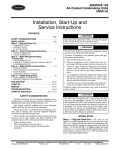
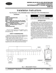
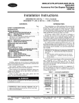
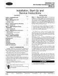
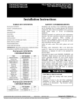
09DK020-094
30GTN,GTR,GUN,GUR040-420/38AH024-134/38AKS028-034
Accessory Low Ambient Operation
Motormaster® V Control
50/60 Hz
Installation and Start-Up Instructions
Part Numbers: 30GT-911---074, 30GT-911---075, 30GT-911---076,
30GT-911---077, 30GT-911---078, 30GT-911---079, 30GT-911---080,
30GT-911---081, 30GT-911---082
CONTENTS
Page
SAFETY CONSIDERATIONS . . . . . . . . . . . . . . . . . . . . . . . . . . . .1
INTRODUCTION . . . . . . . . . . . . . . . . . . . . . . . . . . . . . . . . . . . . . . 1-4
Pre-Installation . . . . . . . . . . . . . . . . . . . . . . . . . . . . . . . . . . . . . . . . .2
APPLICATION NOTES . . . . . . . . . . . . . . . . . . . . . . . . . . . . . . . . 4,5
Winter Start. . . . . . . . . . . . . . . . . . . . . . . . . . . . . . . . . . . . . . . . . . . . .5
INSTALLATION . . . . . . . . . . . . . . . . . . . . . . . . . . . . . . . . . . . . . .5-24
Step 1— Install Field-Fabricated
Wind Baffles and Brackets . . . . . . . . . . . . . . . . . . . . . . . . . . .5
Step 2 — Mount Motormaster V Controls
and Accessories. . . . . . . . . . . . . . . . . . . . . . . . . . . . . . . . . . . . .11
• MOTORMASTER V CONTROLLERS, FUSE
BLOCK RELAYS AND FUSES
• PRESSURE TRANSDUCER
Step 3 — Make Electrical Connections. . . . . . . . . . . . . . . . .11
• 09DK054-094, 30GTN,GTR,GUN,GUR040-110,
230B, 245B, 38AH044-104 (Except Single Circuit)
• 38AH024-034, 38AKS028-044, 09DK020-044
• 38AH044-084 SINGLE CIRCUIT AND 124A/B, 134A/B
• 30GTN,GTR,GUN,GUR130-210, 230A-315A,
330A/B-420A/B
Step 4 — Configure Motormaster V Control. . . . . . . . . . . 24
Step 5 — Configure Unit for Motormaster V
Operation, 30GTN,GTR,GUN,GUR Only . . . . . . . . . . . . . 24
Step 6 — Test Motormaster V Control. . . . . . . . . . . . . . . . . 24
START-UP. . . . . . . . . . . . . . . . . . . . . . . . . . . . . . . . . . . . . . . . . . . 25,26
Drive Programming . . . . . . . . . . . . . . . . . . . . . . . . . . . . . . . . . . . 25
TROUBLESHOOTING . . . . . . . . . . . . . . . . . . . . . . . . . . . . . . . 27,28
EPM Chip . . . . . . . . . . . . . . . . . . . . . . . . . . . . . . . . . . . . . . . . . . . . . 27
Liquid Line Pressure Set Point Adjustment . . . . . . . . . . . 27
Loss of CCN Communications . . . . . . . . . . . . . . . . . . . . . . . . 27
SAFETY CONSIDERATIONS
Installation, start-up, and servicing of this equipment can be
hazardous due to system pressures, electrical components, and
equipment location (roofs, elevated structures, etc.).
Only trained, qualified installers and service technicians
should install, start up, and service this equipment.
When working on this equipment, observe precautions in
the literature and on tags, stickers, and labels attached to the
equipment and any other safety precautions that may apply.
Open all remote disconnects before servicing this equipment. Electrical shock could result in personal injury.
INTRODUCTION
This book contains instructions for the installation and
start-up of the Motormaster V (MMV) control on models
09DK (100%, 50%/50% and 67%/30% split only), 30GTN,
GTR,GUN,GUR040-420, 38AH044-134, and 38AKS028-044.
The 30GTN,GTR,GUN,GUR230-420 units are shipped as 2
separate modules. See Table 1 for details of modular units.
Two Motormaster Accessory Packages are required for
modular units.
Table 1 — 30GTN,GTR,GUN,GUR080-210 and
Associated Modular Units
UNIT
30GTN,GTR,GUN,GUR
080
090
100
110
130
150
170
190
210
ASSOCIATED UNIT MODULES
30GTN,GTR,GUN,GUR
230B
245B
255B, 270B
290B, 315B
None
230A-255A
270A, 330A/B, 360B (50 Hz)
290A, 360A, 360B (60 Hz), 390B
315A, 390A, 420A/B
The Motormaster V control is a motor speed control device
that adjusts condenser fan motor speed in response to declining
liquid refrigerant pressure. A properly applied Motormaster V
control extends the operating range of air-conditioning systems
and permits operation at lower outdoor ambient temperatures.
On 09DK units, the Motormaster V control is used in conjunction with the standard fan cycling controls. See Table 2A
or 2B for the ambient temperatures at which the 09DK units
operate without modification.
Motormaster V control cannot be installed with the highstatic fan option.
Table 2A — Minimum Outdoor-Air Operating
Temperature — 09DK (English)
UNIT
09DK
HEAD
PRESSURE
CONTROL
020,024,
028
FCPSs (1 Fan)†
034,044
FCPSs (2 Fans)†
054,064
FCPSs (2 Fans)†
074-094
FCPSs (2 Fans)†
ATSs (2 Fans)
TD
(F)
30
25
20
30
25
30
30
25
20
30
25
20
COMPRESSOR CAPACITY
(%)*
100
75
50
25
Minimum Outdoor-Air
Temperature (F)
29
34
38
51
38
40
42
53
47
47
46
56
12
19
22
43
22
25
29
47
31
31
36
51
29
34
38
51
38
40
42
53
47
47
46
56
12
19
22
43
22
25
29
47
31
31
36
51
NOTE: See Legend and Notes on page 2.
Manufacturer reserves the right to discontinue, or change at any time, specifications or designs without notice and without incurring obligations.
PC 903
Catalog No. 530-930
Printed in U.S.A.
Form 09/30/38-6SI
Pg 1
506 10-03 Replaces: 09/30/38-5SI
Book 1 2 2
Tab 3a 4a 5c
See Tables 4 and 5 for the Motormaster V control accessory
package usage and contents. Table 6 shows applicable voltages
and motors. Motor or fan blade replacement is not necessary on
most units since the control is compatible with the factoryinstalled fan motors. Only field wiring control is required.
NOTE: Two Motormaster V controls must be added for each
unit (one for each circuit) with the following exceptions:
• 30GTN,GTR,GUN,GUR230-420 modular units require
4 controls (2 per modular unit)
• 38AH124,134 modular units require 4 controls (two per
modular unit)
• 38AH024-034, 38AKS028-044 and 09DK020-044
require only one controller per unit
• 09DK020-044 also requires a field-supplied, 20 x 20 x 8
NEMA 3R enclosure.
Table 2B — Minimum Outdoor-Air Operating
Temperature — 09DK (SI)
UNIT
09DK
HEAD
PRESSURE
CONTROL
TD
(C)
16.7
020,024, FCPSs (1 Fan)† 13.9
028
11.1
16.7
034,044 FCPSs (2 Fans)† 13.9
11.1
16.7
054,064 FCPSs (2 Fans)† 13.9
11.1
16.7
074-094 FCPSs (2 Fans)† 13.9
ATSs (2 Fans)
11.1
COMPRESSOR CAPACITY (%)*
100
75
50
25
Minimum Outdoor-Air
Temperature (C)
–2
1
3
11
3
4
6
12
8
8
8
13
–11
–7
–6
6
–6
–4
–2
8
–1
–1
2
11
–2
1
3
11
3
4
6
12
8
8
8
13
–11
–7
–6
6
–6
–4
–2
8
–1
–1
2
11
LEGEND
ATS
— Air Temperature Switch
FCPS — Fan Cycling Pressure Switch
TD
— Temperature Difference (Saturated Condensing
Temperature – Entering-Air Temperature)
To avoid the possibility of electrical shock, open all disconnects before installing or servicing this accessory.
*Interpolation permitted.
†Additional FCPS required for 66%/33%.
NOTES:
1. Fans on the 09DK020-094 units are controlled by ATSs and
FCPSs.
2. Minimum outdoor temperatures are determined for indoor and
outdoor unit combinations of the same capacity.
Pre-Installation — Inspect the contents of this accessory
package before installing. File a claim with the shipper if you
find shipping damage or if a part is missing.
Table 4 — Motormaster V Control
Package Usage
UNIT
Table 3 shows the ambient temperature at which 30GTN,
GTR,GUN,GUR, 38AH and 38AKS units operate without
modification.
Table 3 — Minimum Outdoor-Air Operating
Temperature — 30GTN,GTR,GUN,GUR and
38AH,AKS
UNIT/SIZE
30GTN,GTR,GUN,GUR040-210
30GTN,GTR,GUN,GUR Modules 230-420
028
38AKS
034
044
024
38AH
028
034
044
054
064
074
38AH*
084
094
104
124
134
30GTN,GTR,
GUN,GUR
TEMPERATURE
F
C
0
–18.0
0
–18.0
31
–0.6
30
–1.1
25
–3.9
53
11.7
50
10.0
49
9.4
50
10.0
48
8.0
39
3.9
31
–0.5
20
–6.7
25
–3.9
14
–10.0
38
3.3
38
3.3
38AH
38AKS
*Data based on standard units operating at 100% of system capacity. Temperatures shown are for circuit A or B, whichever is higher.
09DK
To operate these units below the ambient temperatures listed, Motormaster® V controls (Fig. 1) must be added. Fieldsupplied and installed wind baffles are also required for all
units. The Motormaster V control permits operation of the unit
to an ambient temperature of –20 F (–29 C). The control
regulates the speed of 3-phase fan motors that are compatible
with the control. These motors are factory installed on 60 Hz
models, but must be field installed on 50 Hz models.
SIZE
VOLTAGE
208/230
040-110
380, 400, 460
575
208/230
130-210,
380, 400, 460
230A-315A
575
208/230
230B-315B
380, 400, 460
575
208/230
330A/B-420A/B* 380, 400, 460
575
208/230
024-034
380, 400, 460
575
208/230
044-134
380, 400, 460
575
208/230
028-044
380, 400, 460
575
208/230
020-044
380, 400, 460
575
208/230
054-094
380, 400, 460
575
PACKAGE NO.
30GT-911---080
30GT-911---081
30GT-911---082
30GT-911---074
30GT-911---075
30GT-911---076
30GT-911---080
30GT-911---081
30GT-911---082
30GT-911---074
30GT-911---075
30GT-911---076
30GT-911---077
30GT-911---078
30GT-911---079
30GT-911---080
30GT-911---081
30GT-911---082
30GT-911---077
30GT-911---078
30GT-911---079
30GT-911---077
30GT-911---078
30GT-911---079
30GT-911---080
30GT-911---081
30GT-911---082
*Two accessory packages required for modular units.
2
Table 5 — Motormaster® V Control Package Contents
ITEM
Controller, 230 V,
2 HP
Controller, 460 V,
2 HP
Controller, 575 V,
2 HP
Controller, 230 V,
5 HP
Controller, 460 V,
5 HP
Controller, 575 V,
5 HP
Fuse, 15 A,
Class CC
Fuse, 20 A,
Class CC
Fuse, 30 A,
Class CC
Wires
MOTORMASTER V CONTROL PACKAGE NUMBER
30GT-911---075 30GT-911---076 30GT-911---077 30GT-911---078 30GT-911---079 30GT-911---080 30GT-911---081 30GT-911---082
Item Description (Qty)
HR46TN001
HR46TN001
—
—
—
—
—
—
(1)
(2)
HR46TN002
HR46TN002
—
—
—
—
—
—
(1)
(2)
HR46TN003
HR46TN003
—
—
—
—
—
—
(1)
(2)
30GT-911---074
—
—
—
HR46TN004
(2)
—
—
HR46TN005
(2)
Wire Ties
Wire Connectors
Connector
Varnish Cloth
1/ in. Flare Tee
4
Transducer
Transducer Cable
Fuse Block
10AB-16 x 1/2 in. Screw
8 x 3/4 in. Screw
Relay
10 x 1/2 in. Screw
—
—
—
—
—
—
—
—
—
—
—
—
—
HR46TN006
(2)
HY10KB151
(6)
—
—
—
—
—
HY10KB200
(6)
—
HY10KB300
(6)
14 AWG,
8 in. long wires (6)
14 AWG,
6 in. long wires (6)
14 AWG,
10 in. long wires (6)
—
—
—
—
—
—
—
—
HY10LF014
(3)
HY10LF014
(3)
—
HY10LF014
(6)
HY10LF014
(6)
—
HY10LF014
(3)
—
—
HY10LF014
(6)
—
—
—
—
—
—
—
—
—
16 AWG,
8 in. long wires (6)
16 AWG,
6 in. long wires (6)
16 AWG,
10 in. long wires (6)
—
—
—
16 AWG, 38 in. long wires (6)
—
—
—
—
16 AWG,10 in. long wires (3)
16 AWG, 40 in. long wires (6)
16 AWG, 6 in. jumper wires (2)
Wire Ties (7)
—
HW60EA001 (1)
48DA510141 (1)
EC36SZ061 (1)
HK05YZ007 (1)
30GT415784 (1)
HY11UT035 (1)
AL78AG216 (2)
AL56AU168 (6)
HN61KK035 (1)
(2)
Wire Connectors (6)
—
—
—
HK05YZ007 (2)
30GT415784 (2)
HY11UT035 (2)
AL78AG216 (4)
AL56AU168 (12)
HN61KK035 (2)
(4)
—
HW60EA001 (1)
48DA510141 (1)
EC36SZ061 (2)
HK05YZ007 (2)
30GT415784 (2)
HY11UT035 (2)
AL78AG216 (4)
AL56AU168 (12)
HN61KK035 (2)
(4)
AWG — American Wire Gage
NOTE: The 09DK020 also requires a field-supplied, 20 x 20 x 8 NEMA 3R enclosure. Hoffman A-20RZ08HCLO with A-20P20 back panel.
BLU
YEL
BLK
FROM FUSE BLOCK
B
13B
13C
12 13A
2
2
12 5 6
MMV
TERMINAL
BOARD
TO PRESSURE
TRANSDUCER
5
2
9
FR
13
1
*CONNECT FOR START
SIGNAL. REFER TO
TABLE 8. START CONTACT
14
3
TO FAN
CONTACTOR
COIL
TO MOTOR(S)
Fig. 1 — Motormaster V Control
3
START
CONTACT
DETAIL
Table 6 — Applicable Voltages and Motors
UNIT NAMEPLATE VOLTAGE*
COMPATIBLE MOTORS
208-230/3/60
HD52AK654, HD52AK002
380-3-60
HD52GE381, HD52GE382
460-3-60, 380/415-3-50
HD52AK654, HD52AK002
380/415-3-50 (Low noise fans)
HD56AK653
575-3-60
HD52GE576, HD52GE577
Table 7B — Minimum Capacity Step (%) —
30GTN,GTR,GUN,GUR — 50 Hz
UNIT/SIZE
30GTN,GTR,GUN,GUR
STANDARD
UNIT
040
045
050
060
070
080; Module 230B
090; Module 245B
100; Modules 255B,
270B
110; Modules 290B,
315B
130
150; Modules 230A,
245A, 255A
170; Modules 270A,
330A/B, 360B
190; Modules 290A,
360A, 390B
210; Modules 315A
390A, 420A/B
24*
31*
28*
33*
19*
22
14
*Not all voltages are available for all units. See base unit installation instructions for available voltages.
APPLICATION NOTES
For the 09DK units, the information in this book is applicable when either 100%, 50/50% or 67%/33% condenser coil
circuiting is used.
There are no minimum capacity step (%) tables with the
09DK condensers, because capacity steps are dependent on the
compressor-bearing unit. Refer to base unit product data literature for further details.
The 09DK020-044 units require a field-supplied, 20 x 20 x
8 NEMA 3R enclosure.
Corrosion-inhibited antifreeze solution for 30GTN,GTR,
GUN,GUR chiller use must be added to the cooler fluid loop to
protect it to temperatures 15° F (9° C) below the lowest expected outdoor temperature.
Widely varying cooling loads are often encountered during
low ambient temperature operation of the 30GTN,GTR, GUN,
GUR chiller. To minimize compressor cycling as a result of
these conditions, provide sufficient volume in the chiller fluid
loop, adding a properly baffled storage tank to the system if
necessary. At least 6 gal per ton (6.5 L per kW) of refrigeration
is recommended for a moderate system load.
STANDARDUNIT WITH
ACCESSORYUNLOADER(S)
—
21†
20†
18†
16†
11
9
8
7
8
11
6
11
6
13
9
11
8
7
17
8
10
6
13
6
9
5
17
11
9
7
Table 7C — Minimum Capacity Step (%) —
38AH — 50/60 Hz
Table 7A — Minimum Capacity Step (%)
30GTN,GTR,GUN,GUR — 60 Hz
STANDARD
UNIT
25*
24*
31*
28*
33*
22
18
16
14
14
13
*A1 compressor with standard unloader, OR
A1 compressor with standard unloader and B1 compressor with accessory
unloader.
†A1 compressor with standard unloader and accessory unloader, and B1 compressor with accessory unloader, OR
A1 compressor with standard unloader and accessory unloader, and B1 compressor with 2 accessory unloaders.
Operation at low ambient temperature is not recommended
if the minimum load on the 30GTN,GTR,GUN,GUR
chiller or the 38AH condensing unit is below its minimum
step of capacity. Unstable operation may result. See
Table 7A, 7B, 7C, or 7D.
UNIT/SIZE
30GTN,GTR,GUN,GUR
040
045
050
060
070
080; Module 230B
090; Module 245B
100; Modules 255B, 270B
110; Modules 290B, 315B
130
150; Modules 230A,
245A, 255A
170; Modules 270A,
330A/B
190; Modules 290A,
360A/B, 390B
210; Modules 315A,
390A, 420A/B
STANDARD
UNIT WITH
ACCESSORY
UNLOADER(S)
21†
18†
15†
16†
11†
8
7
UNIT
38AH
STANDARD
UNIT
024
028
034
044
054
064
074
084
094
104
Modules
124A, 124B,
134A
Module 134B
33
33
28
25
21
32
29
33
22
18
OPTIONAL VAV UNIT WITH
ELECTRIC UNLOADERS OR
STANDARD UNIT WITH
ACCESSORY UNLOADER(S)
ON LEAD COMPRESSOR
17
17
14
—
22
16
14
17
22
17
32
9
29
8
VAV
LEGEND
— Variable Air Volume
Table 7D — Minimum Capacity Step (%) —
38AKS — 50/60 Hz
UNIT
38AKS
028
034
044
*A1 compressor with standard unloader, OR
A1 compressor with standard unloader and B1 compressor with accessory
unloader.
†A1 compressor with standard unloader and accessory unloader, and B1 compressor with accessory unloader, OR
A1 compressor with standard unloader and accessory unloader, and B1 compressor with 2 accessory unloaders.
4
STANDARD
UNIT
33
33
33
Wind baffles and brackets must be field fabricated for all
units (except 38AH024-034, 38AKS028-044 and 09DK020044) to ensure proper cooling cycle operation at low-ambient
temperatures with Motormaster® V controls. See Fig. 2-10 for
the number and sizes of brackets and baffles required and for
bracket and baffle details. Use 20-gage (1 mm) galvanized
sheet metal, or similar corrosion-resistant material for the baffles. Use 14-gage (1.85 mm) galvanized sheet metal or similar
corrosion-resistant material for the brackets. Use field-supplied
screws to attach baffles and brackets to unit. Screws should be
1/ -in. (6.3 mm) diameter or larger. Drill required screw holes
4
for mounting baffles and brackets.
Winter Start — All 30GTN,GTR,GUN,GUR chillers have
winter start features included in their microprocessor control
logic. All 38AH and 38AKS units have winter start features
included in their standard controls. The 09DK air-cooled
condenser sections do not need to be directly modified, however, the total system may require winter start control. Refer to
indoor base unit installation instructions. No additional provisions are necessary.
INSTALLATION
Step 1 — Install Field-Fabricated Wind Baffles
and Brackets
To avoid damage to refrigerant coils and electrical components, use extreme care when drilling screw holes and
screwing in fasteners.
To avoid the possibility of electrical shock, open all disconnects before installing or servicing this accessory.
Summary of Baffles and Brackets
BAFFLE TYPE AND QUANTITY
UNIT
09DK054,064
09DK074,084
09DK094
30GTN,GTR,GUN,GUR040-050
30GTN,GTR,GUN,GUR060,070
30GTN,GTR,GUN,GUR080,090; Modules 230B, 245B
30GTN,GTR,GUN,GUR100,110; Modules 255B-315B
38AH094,104
38AH044-064; Modules 124A, 124B, 134A
38AH074,084; Module 134B
A
B
C
D
E
F
—
2
2
—
2
2
—
2
—
2
—
—
4
—
—
4
—
4
—
—
—
—
—
—
—
—
2
—
—
—
—
—
—
—
—
—
4
—
—
—
—
4
—
—
4
—
—
—
—
4
2
—
—
2
—
—
—
—
2
—
BRACKETS*
Length
Qty
in.
mm
6
363/8
924
8
443/8
1127
8
443/8
1127
6
363/8
924
8
443/8
1127
8
443/8
1127
8
443/8
1127
8
443/8
1127
6
363/8
924
8
443/8
1127
*See Fig. 7 for bracket construction.
BAFFLE
A
B
C
D
E
F
BAFFLE SIZE
in.
mm
26 x 4111/16
660 x 1059
47 x 417/8
1194 x 1064
32 x 4111/16
813 x 1059
7
1549 x 1064
61 x 41 /8
7
42 x 41 /8
1067 x 1064
85 x 3311/16 2159 x 856
NOTES:
1. Unit 09DK condensers are not provided with compressors.
2. See Fig. 3-6 for baffle construction.
09DK054,064/30GTN,GTR,GUN,GUR040-050/
38AH044-064 AND MODULES 124A/B, 134A
09DK094/
30GTN,GTR,GUN,GUR080,090
AND MODULES 230B, 245B/ 38AH094, 104
09DK074,084/
30GTN,GTR,GUN,GUR060,070/
38AH074,084 AND MODULE 134B
30GTN,GTR,GUN,GUR100,110 AND
MODULES 255B-315B
Fig. 2 — Baffle Configuration for 09DK/30GTN,GTR,GUN,GUR040-110 and Associated Modular Units
(See Table 1)/38AH044-134 Low-Ambient Operation
5
LEGEND
TYP — Typical
NOTES:
1. Dimensions in ( ) are millimeters.
2. All units listed as modules consist of one
module “A” plus one module “B.”
Fig. 3 — “A” Baffle for Coil Section (09DK074-094/30GTN,GTR,GUN,GUR060-090 and
Modules 230B, 245B/38AH074-104 and Module 134B);
“B” Baffle for Coil Section (09DK094/30GTN,GTR,GUN,GUR080,090 and Modules 230B, 245B/38AH094,104)
LEGEND
TYP — Typical
NOTES:
1. Dimensions in ( ) are millimeters.
2. All units listed as modules consist of one
module “A” plus one module “B.”
Fig. 4 — “C” and “D” Baffles for Coil Section
(30GTN,GTR,GUN,GUR100,110 and Modules 255B-315B)
6
LEGEND
TYP — Typical
NOTES:
1. Dimensions in ( ) are millimeters.
2. All units listed as modules consist of one
module “A” plus one module “B.”
Fig. 5 — “E” Baffles for Coil Section
(09DK074,084/30GTN,GTR,GUN,GUR060,070;38AH074,084; Module 134B)
LEGEND
TYP — Typical
NOTES:
1. Dimensions in ( ) are millimeters.
2. All units listed as modules consist of one
module “A” plus one module “B.”
Fig. 6 — “F” Baffles for Coil Section
(09DK054,064/30GTN,GTR,GUN,GUR040-050/38AH044-064; Modules 124A/B and 134A)
7
09DK054,064/30GTN,GTR,GUN,GUR040-050/
38AH044-064 AND MODULES 124A/B, 134A
09DK074-094/30GTN,GTR,GUN,GUR060-110
AND MODULES 230B-315B/38AH074-104 AND MODULE 134B
LEGEND
TYP — Typical
NOTES:
1. Dimensions in ( ) are millimeters.
2. All units listed as modules consist of one
module “A” plus one module “B.”
Fig. 7 — Brackets for Coil Section (09DK/30GTN,GTR,GUN,GUR040-110 and
All Associated Modular Units [See Table 1]/38AH044-134 Units)
8
Summary of Baffles and Brackets
BAFFLE TYPE AND QUANTITY
UNIT
30GTN,GTR,GUN,GUR
C
D
E
Qty
130-170,230A-270A
190-210,290A,315A
330A/B†
360A/B (50 Hz)†
360A/B (60 Hz)†, 390A/B†, 420A/B†
2
4
4
6
8
4
8
8
12
16
2
—
4
2
—
14
16
28
30
32
BRACKETS*
Length
in.
483/8
483/8
483/8
483/8
483/8
mm
1229
1229
1229
1229
1229
*See Fig. 10 for bracket construction.
†Total unit (includes both modules).
BAFFLE
C
D
E
BAFFLE SIZE
in.
mm
660 x 1160
26 x 4511/16
47 x 457/8
1194 x 1165
80 x 4511/16
2032 x 1160
NOTE: See Fig. 9 for baffle construction.
30GTN,GTR,GUN,GUR130-170 AND MODULES 230A-270A, 330A/B, 360B (50 Hz)
30GTN,GTR,GUN,GUR190-210 AND MODULES 290A, 315A, 360A (50 AND 60 Hz),
360B (60 Hz), 390A/B, 420A/B
Fig. 8 — Baffle Configuration for 30GTN,GTR,GUN,GUR, Sizes 130-210, 230A-315A, 330A/B-420A/B
Low Ambient Operation
9
LEGEND
TYP — Typical
NOTE: Dimensions in (
) are millimeters.
Fig. 9 — “C,” “D,” and “E” Baffles for 30GTN,GTR,GUN,GUR130-210, 230A-315A, 330A/B-420A/B
LEGEND
TYP — Typical
NOTE: Dimensions in (
) are millimeters.
Fig. 10 — Brackets for Coil Section — 30GTN,GTR,GUN,GUR130-210, 230A-315A, 330A/B-420A/B
10
NOTE: Ensure that the valve is not backseated or the pressure
transducer will not read correctly.
Step 2 — Mount Motormaster® V Controls and
Accessories
Step 3 — Make Electrical Connections
To avoid electric shock and personal injury open and tag all
electrical disconnects before installing or servicing unit.
To avoid damage to the small terminals on the Motormaster V control, use care when tightening the compression terminals and use the proper size screwdriver.
Hazard of electric shock! Wait three minutes after disconnecting incoming power before servicing drive. Capacitors
retain charge after power is removed.
DO NOT connect incoming AC power to Motormaster V
output terminals T1, T2, and T3! Severe damage to the control will result.
NOTE: Two Motormaster V controllers, 2 fuse blocks, 2 relays
and 2 pressure transducers must be added per unit (1 per refrigerant circuit) with the following exceptions:
• 38AH 124, 134 units and 30GTN,GTR,GUN,GUR
230-420 modular units will require 2 kits per unit
(4 controllers, 4 fuse blocks, 4 relays, and 4 pressure
transducers). Two of each item will be installed in each
of the 2 control boxes.
• 38AH044-084 single circuit and 09DK054-094 100%
circuiting units will require 2 controllers, 2 fuse blocks,
2 relays, and 2 pressure transducers. The pressure transducers from each control will be attached at the same
point on the liquid line.
• 38AH024-034, 38AKS028-044 and 09DK020-044 units
will only require one controller, fuse block, one relay
and transducer.
MOTORMASTER V CONTROLLERS, RELAYS, FUSE
BLOCKS AND FUSES — Refer to Fig. 11-16 for the proper
mounting locations. Use the 8 x 3/4-in. screws provided with
kit to mount controls and fuse blocks to control box. Use 10 x
1/ -in. screws to mount relays. See Table 5 for proper fuse sizes
2
for each kit. The 09DK020-044 units require a field-supplied,
20 x 20 x 8 NEMA 3R enclosure.
PRESSURE TRANSDUCER — Install pessure transducer(s)
in the proper location on the liquid line. See Fig. 17-22.
30GTN,GTR,GUN,GUR Units — Mount one pressure transducer to the Schrader service valve port near each liquid line
valve as shown in Fig. 17. Identify which circuit is A and B and
retain this information for use in later steps.
38AH024-104 and 09DK020-094 and 38AKS028-044 Units
(Except Single Circuit or 100% Circuit) — See Fig. 18-20.
Install a field-supplied Schrader port and valve into the liquid
line near the liquid line valve on each circuit. Mount pressure
transducer on this valve. For 09DK020-044 dual circuit units,
install the pressure transducer on the lead circuit. If unit has
already been piped and charged, mount pressure transducer
to each circuit’s liquid line valve port using tees provided.
Identify which circuit is A and B and retain this information for
use in later steps.
NOTE: Ensure that the liquid line valve is not backseated or
the pressure transducer will not read correctly.
38AH044-084 Single Circuit, 38AH124A/B and 09DK054094 100% Circuiting Units — Install 2 field-supplied Schrader
ports with valves on the common liquid line near the liquid line
valve. Mount transducers to these valve ports. If unit has already been piped and charged, mount pressure transducers to
liquid-line valve port using tees provided. (See Fig. 22.)
NOTE: Ensure that the valve is not backseated or the pressure
transducer will not read correctly.
38AH124A/B and 134A/B units — Install 2 Schrader ports
with valves on the common liquid line near the liquid line
valve for unit module A. Repeat process for unit module B. If
unit has already been piped and charged, mount pressure transducers to liquid line valve ports using tees provided.
The required electrical connections for the Motormaster V
control are for incoming power, outgoing power, and control
signals. All required wires are provided in each kit. Detailed
instructions for each model are shown below:
09DK054-094 (see Fig. 23), 30GTN,GUR,GUN,GUR040-110,
230B, 245B, (refer to Fig. 24), 38AH044-104 (Except Single
Circuit) (refer to Fig. 24) (P/N 30GT-911---080,081,082)
1. Mark and then disconnect shielded power cables (FM-1
and FM-2) from fan motor contactors FC-A1 and FC-B1
(FC1 and FC2 for 09DK). Retain all fasteners for later use.
Disconnect power cable ground wires at the control box.
2. Cut ring terminals from black power wires only. Strip
back 1/4 inch. Do not cut off ring terminal on ground wire.
3. Attach newly stripped wires 1, 2, 3 from FM-1 to MM-A
terminals T1, T2, T3 respectively. Re-attach ground wire to
control box back wall using ground screw near Motormaster V controller. Be careful not to attach wires to B– or B+.
4. Attach newly stripped wires 1, 2, 3 from FM-2 to MM-B
terminals T1, T2, T3 respectively. Re-attach ground wire
to control box wall using ground screw punch near
Motormaster V controller.
5. Install 40-in. BLK, YEL, BLU wires from fan circuit
breaker (FCB-1) (or TB1 for 09DK units only) to fuse
block MMF-A. Install 38-in. BLK, YEL, BLU wires
from MMF-A to input power terminals L1, L2, L3
respectively on MM-A.
6. Install 40-in. BLK, YEL, BLU wires from fan circuit
breaker FCB-2 (or FC-B1 [FC2] if FCB-2 is not used) to
fuse block MMF-B. Install 38-in. BLK, YEL, BLU wires
from MMF-B to input power terminals L1, L2, L3
respectively on MM-B.
7. Attach sensor cables to pressure transducers and route
cable to control box. Ensure that the cable is separated
from sharp edges. Route cable through knockouts in
bottom of control box. Seal cable to control box using
supplied varnish cloth and metal conduit connector. Wrap
varnish cloth around wires to separate wires from metal
connector. Trim lengths of cable as desired but ensure that
shield drain wire is used.
8. Attach RED, GRN, BLK wires from sensor cables to
Motormaster controls terminal block 6, 5 and 2 respectively according to Fig. 1, 23 and 24. Attach shield drain
wire to control box near Motormaster control using the
original ground screw. Ensure that the pressure transducer
from refrigerant circuit A is attached to MM-A.
9. Attach VIO and the RED wires from FR-1 fan relay
terminals 5 and 9 to Motormaster control. The RED wire
connects at terminals 2, the VIO wire to the terminal listed
in Table 8. Repeat for circuit B using VIO and RED wires.
10. Attach GRA and the RED wires to FR-1 terminals 13 and
14. Attach the other ends to FC-1 terminals C1 and C2.
Repeat for circuit B using VIO and RED wires.
11
supplied varnish cloth and metal conduit connector. Wrap
varnish cloth around wires to separate wires from metal
connector. Trim lengths of cable as desired but ensure that
shield drain wire is used.
8. Attach RED, GRN, BLK wires from sensor cables to
Motormaster controls terminal block 6, 5 and 2 respectively, see Fig. 1 and 26. Attach shield drain wire to control box near Motormaster control using the original
ground screw.
9. Attach VIO and the RED wires from FR-1 fan relay
terminals 5 and 9 to Motormaster control. The RED wire
connects at terminals 2, the VIO wire to the terminal listed
in Table 8. Repeat for circuit B using VIO and RED wires.
10. Attach GRA and the RED wires to FR-1 terminals 13 and
14. Attach the other ends to FC-1 terminals C1 and C2.
Repeat for circuit B using VIO and RED wires.
30GTN,GUR,GUN,GUR130-210, 230A-315A, 330A/B420A/B (refer to Fig. 27): (P/N 30GT-911---074,075,076)
1. Mark and then disconnect shielded power cables FM-5, 7
from fan motor contactors FC-A1 and cables FM-6, 8
from FC-B1. Retain all fasteners for later use. Disconnect
ground wires from control box back wall.
2. Cut ring terminals from black power wires on each cable
labeled 1, 2, 3 only. Strip back 1/2 inch. Do not cut off ring
terminal on ground wire.
3. Use the crimp connectors supplied to splice the black
wire (marked #1), from cables FM-5 and FM-7 along
with one of the 6-in. black wires in the kit. Connect the
other end of the 6-in. black wire to lug T1 on the bottom
of the control MM-A. Make similar connections for black
wires marked #2 and #3 from each cable and connect
them to lugs T2 and T3 of the MM-A control.
4. Use the crimp connectors supplied to splice the black
wire (marked #1), from cables FM-6 and FM-8 along
with one of the 6-in. black wires in the kit. Connect the
other end of the 6-in. black wire to lug T1 on the bottom
of the control MM-B. Make similar connections for black
wires marked #2 and #3 from each cable and connect
them to lugs T2 and T3 of the MM-B control.
5. Reconnect ground wires to control box back wall near
Motormaster controllers using original ground screws.
6. Install 30-in. BLK, YEL, BLU wires from fan circuit
breaker FCB-1 to fuse block MMF-A. Install 8-in. BLK,
YEL, BLU wires from MMF-A to input power terminals
L1, L2, L3 respectively on MM-A.
7. Install 30-in. BLK, YEL, BLU wires from fan circuit
breaker FCB-2 (or FCB-1 if 2 is not used) to fuse block
MMF-B. Install 8-in. BLK, YEL, BLU wires from
MMF-A to input power terminals L1, L2, L3 respectively
on MM-B.
8. Attach sensor cables to pressure transducers and route
cable to control box. Ensure that the cable is separated
from sharp edges. Route cable through grommet on left
side of control box. Trim lengths of cable as desired but
ensure that shield drain wire is used.
9. Attach RED, GRN, BLK wires from sensor cables to
Motormaster controls terminal block 6, 5 and 2 respectively according to Fig. 1 and 27. Attach shield drain wire
to control box near Motormaster control using the original ground screw. Ensure that the pressure transducer
from refrigerant circuit A is attached to MM-A.
10. Attach VIO and the RED wires from FR-1 fan relay
terminals 5 and 9 to Motormaster control. The RED wire
connects at terminals 2, the VIO wire to the terminal listed
in Table 8. Repeat for circuit B using VIO and RED wires.
11. Attach GRA and the RED wires to FR-1 terminals 13 and
14. Attach the other ends to FC-1 terminals C1 and C2.
Repeat for circuit B using VIO and RED wires.
38AH024-034, 38AKS028-044 and 09DK020-044 (See
Fig. 25)
1. Mark the shielded cable from FM1 to FC1 at Motormaster® V controller location. The cable will be cut at
this point, so be sure to allow enough slack to reach the
Motormaster V controller and fuse block.
2. In the area marked, cut the cover off of the cable. Cut
each individual wire and mark both ends for identification. Mark wires 1, 2 and 3.
3. Strip the ends of the wires coming from FC-1, and attach
them to one side of the fuse block.
4. Install the 10-in. black, yellow and blue wires from the
fuse block to the Motormaster V terminal block (L1, L2
and L3). The BLK, YEL, and BLU wires are on the same
fuse as wires 1, 2 and 3, and are on Motormaster V terminals L1, L2 and L3, respectively.
5. Install the other end of the cut wires (on the FM side)
into the Motormaster V terminal block T1, T2 and T3
terminals.
6. Ground shield with the ground wire from each side of the
cut shielded cable.
7. Remove wires from FC-1, T1/T2/T3 and connect at FU1
(or TB1 if FU1 not used).
8. Attach the sensor cable to the pressure transducer and
route it to the controller. Ensure that the cable is separated
from all sharp edges. Trim the lengths of the cable as
desired, but ensure that shield drain wire is used.
9. Attach the RED, GRN and BLK wires from the sensor
cables to the Motormaster V control terminal block positions 6, 5 and 2, respectively. Attach shield drain wire to
the panel where the Motomaster V is mounted.
10. Attach VIO and the RED wires from FR-1 fan relay
terminals 5 and 9 to Motormaster control. The RED wire
connects at terminals 2, the VIO wire to the terminal listed
in Table 8. Repeat for circuit B using VIO and RED wires.
11. Attach GRA and the RED wires to FR-1 terminals 13 and
14. Attach the other ends to FC-1 terminals C1 and C2.
Repeat for circuit B using VIO and RED wires.
38AH044-084 SINGLE CIRCUIT AND 124A/B, 134A/B
(refer to Fig. 26): (P/N 30GT-911---080,081,082)
1. Mark and then disconnect shielded power cables (FM-1
and FM-2) from fan motor contactor FC-A1. Retain all
fasteners for later use. Remove ground wires from control
box back wall.
2. Cut ring terminals from black power wires only. Strip
back 1/4 inch. Do not cut off ring terminal on ground wire.
3. Attach newly stripped wires 1, 2, 3 from FM-1 to MM-A
terminals T1, T2, T3 respectively. Re-attach ground wire
to control box back wall using ground screw near Motormaster V controller.
4. Attach newly stripped wires 1, 2, 3 from FM-2 to MM-B
terminals T1, T2, T3 respectively. Re-attach ground wire
to control box back wall using ground screw punch near
Motormaster V controller.
5. Install 40-in. BLK, YEL, BLU wires from fan circuit
breaker FCB-1 to fuse block MMF-A. Install 38-in. BLK,
YEL, BLU wires from MMF-A to input power terminals
L1, L2, L3 respectively on MM-A.
6. Install 40-in. BLK, YEL, BLU wires from fan circuit
breaker FCB-2 (or FCB-1 is 2 is not used) FC-A1 to fuse
block MMF-B. Install 38-in. BLK, YEL, BLU wires
from MMF-B to input power terminals L1, L2, L3
respectively on MM-B.
7. Attach sensor cables to pressure transducers and route
cable to control box. Ensure that the cable is separated
from sharp edges. Route cable through knockouts in
bottom of control box. Seal cable to control box using
12
09DK054,064
ATS
CR
DU
EQUIP
FC
FR
—
—
—
—
—
—
Air Temperature Switch
Control Relay
Dummy Terminal
Equipment
Fan Contactor
Fan Relay
GND
MM
MMF
NEC
TB
TRAN
09DK074-094
—
—
—
—
—
—
LEGEND
Ground
Motormaster Control
Motormaster Relay
National Electrical Code
Terminal Block
Transformer
Fig. 11 — Motormaster® V Control Location; 09DK054-094 Units
(074-094 Units Shown)
13
Terminal Block Connection
Marked Terminal
Unmarked Terminal
Factory Wiring
Field Wiring
Fig. 12 — Motormaster® V Control Location; 38AH024-034, 38AKS028-044
Fig. 13 — Motormaster V Control Location; 09DK020-044
14
13
14
13
14
FUSE BLOCK
MOTORMASTER V
ACCESSORY
1
2
30GTN,GTR,GUN,GUR080,090;
MODULES 230B,245B/
38AH094,104
CONTROL
BOX
CONTROL
BOX
RELAY
1
2
30GTN,GTR,GUN,GUR100,110;
MODULES 255B,315B
CB
CCPR
CR
DU
EQUIP
FC
FCB
FR
GND
LPR
MMF
NEC
OPR
PR
PRI
PW
SDR
SEC
TB
TDR
TM
TR
VAV FIOP
XL
—
—
—
—
—
—
—
—
—
—
—
—
—
—
—
—
—
—
—
—
—
—
—
—
LEGEND
Circuit Breaker
Capacity Control Pressure Relay
Control Relay
Dummy Terminal
Equipment
Fan Contactor
Fan Circuit Breaker
Fan Relay
Ground
Low Pressure Relay
Motormaster® Fuse
National Electrical Code
Oil Pressure Relay
Power Relay
Primary
Part Wind
Solenoid Drop Relay
Secondary
Terminal Block
Time-Delay Relay
Timer Motor
Timer Relay
Variable Air Volume Factory-Installed Option
Across-the-Line
Fig. 14 — 38AH044-084,124,134; 30GTN,GTR,GUN,GUR040-070 Component Arrangement
15
MOTORMASTER V
ACCESSORY
FUSE
BLOCK
RELAY
1
2
30GTN,GTR,GUN,GUR080,090;
MODULES 230B,245B/
38AH094,104
14
13
14
CONTROL
BOX
CONTROL
BOX
13
1
CB
CCPR
CR
2
DU
EQUIP
FC
30GTN,GTR,GUN,GUR100,110; FCB
MODULES 255B,315B
FR
GND
LPR
MMF
NEC
OPR
PR
PRI
PW
SDR
SEC
TB
TDR
TM
TR
VAV FIOP
XL
—
—
—
—
—
—
—
—
—
—
—
—
—
—
—
—
—
—
—
—
—
—
—
—
LEGEND
Circuit Breaker
Capacity Control Pressure Relay
Control Relay
Dummy Terminal
Equipment
Fan Contactor
Fan Circuit Breaker
Fan Relay
Ground
Low Pressure Relay
Motormaster® Fuse
National Electrical Code
Oil Pressure Relay
Power Relay
Primary
Part Wind
Solenoid Drop Relay
Secondary
Terminal Block
Time-Delay Relay
Timer Motor
Timer Relay
Variable Air Volume Factory-Installed Option
Across-the-Line
Fig. 15 — 38AH094-104; 30GTN,GTR,GUN,GUR080-110 (and Associated Modular Units)
Component Arrangement (Typical) (38AH094-104 Shown)
16
FUSE BLOCK
MOTORMASTER V
ACCESSORY
RELAY
13
14
13
14
FC
FCB
FR
MM
MMF
—
—
—
—
—
LEGEND
Fan Contactor
Fan Circuit Breaker
Fan Relay
Motormaster® Control
Motormaster Fuse Block
Fig. 16 — 30GTN,GTR,GUN,GUR130-210 (and Associated Modular Units)
Component Arrangement
17
MMPT-A & MMPT-B
CABLE ROUTING
TRANSDUCER MMPT-B (040-110) MMPT-A (130-210)
FROM CORRESPONDING MMV (VFD) IN CONTROL BOX
TRANSDUCER MMPT-A (040-110) MMPT-B (130-210)
FROM CORRESPONDING MMV (VFD) IN CONTROL BOX
LEGEND
MM
— Motormaster® Control
MMPT — Motormaster Pressure Transducer
VFD
— Variable Frequency Drive
Fig. 17 — 30GTN,GTR,GUN,GUR Pressure Transducer Location
18
Fig. 18 — 38AH Dual-Circuit Pressure Transducer Location
19
*Field supplied.
NOTES:
1. Hot gas lines should rise above refrigerant level in
condenser circuit.
2. Trap should be installed on hot gas lines to prevent
condenser oil and refrigerant vapor migration from
accumulating on compressor heads during off cycle.
3. Pitch all horizontal lines downward in the direction of
refrigerant flow.
4. Refer to Carrier System Design Manual, part 3 for
proper piping sizes and design.
Fig. 19 — Typical Piping for 09DK Condenser With a Dual Split System
MOUNT TRANSDUCER TO LIQUID LINE
SERVICE VALVE USING TEE SUPPLIED IN KIT
CIRCUIT NO. 1
Fig. 20 — 38AH024-034 Unit Pressure Transducer Location
20
MOUNT
TRANSDUCERS
ON LIQUID LINE
SERVICE VALVE
USING TEES
SUPPLIED IN KIT
COMPRESSOR END, RIGHT-SIDE ACCESS DOOR
Fig. 21 — 38AKS028-044 Pressure Transducer Location
Fig. 22 — 38AH Single-Circuit Pressure Transducer Location
21
MOTORMASTER V ACCESSORY
100%, 50%/50% AND 67%/33%
CAPACITY SPLITS ONLY
EQUIP
FM
GND
MM
MMF
MMPT
—
—
—
—
—
—
LEGEND
Equipment
Fan Motor
Ground
Motormaster® Control
Motormaster Fuse Block
Motormaster Pressure Transducer
—
—
—
—
—
LEGEND
Fan Circuit Breaker
Fan Motor
Motormaster Control
Motormaster Fuse Block
Motormaster Pressure Transducer
Fig. 23 — 09DK054-094 Schematic Diagram
MOTORMASTER V ACCESSORY
FCB
FM
MM
MMF
MMPT
Fig. 24 — 38AH044-104 (Dual Circuit), 30GTN,GTR,GUN,GUR040-110 (and Associated Modular Units)
Schematic Diagram
22
MOTORMASTER V ACCESSORY
FM
FU
MM
MMF
MMPT
TB
—
—
—
—
—
—
LEGEND
Fan Motor
Fuse
Motormaster® Control
Motormaster Fuse Block
Motormaster Pressure Transducer
Terminal Block
Fig. 25 — 38AH024-034, 38AKS028-044 and 09DK020-044 Schematic Diagram
MOTORMASTER V ACCESSORY
FCB
FM
MM
MMF
MMPT
—
—
—
—
—
LEGEND
Fan Circuit Breaker
Fan Motor
Motormaster Control
Motormaster Fuse Block
Motormaster Pressure Transducer
Fig. 26 — 38AH Single Circuit 044-084, 124A/B, 134A/B Schematic Diagram
23
MOTORMASTER V ACCESSORY
FCB
FM
MM
MMF
MMPT
—
—
—
—
—
LEGEND
Fan Circuit Breaker
Fan Motor
Motormaster® Control
Motormaster Fuse Block
Motormaster Pressure Transducer
Fig. 27 — 30GTN,GTR,GUN,GUR130-210 (and Associated Modular Units) Schematic Diagram
Step 4 — Configure Motormaster® V Control —
Step 5 — Configure Unit for Motormaster V Operation, 30GTN,GTR,GUN,GUR Only — The unit must
The Motormaster V control is configured for 1 of 12 operation
modes based on the inputs to the small terminal block on the
face of the control. 30GTN,GTR, 38AH and 38AKS units use
operating modes 1-4 and 30GUN,GUR units use modes 9-12.
09DK units may use any of these modes according to unit voltage and refrigerant. In these configurations, the MMV modulates the fan speed based on a 0 to 5V feedback signal on pin 5.
To configure the Motormaster V control, install a jumper
into the control terminal block according to Table 8 below. The
start contact is required to configure the drive for 50/60 Hz
operation and input voltage. A jumper is used to enable the
R-134a set point rather than the default R-22 set point. Once
the control is powered in Step 6 below, it will change to the
mode selected according to the inputs. No additional programming is required. Note that the pressure transducer must be
attached for proper configuration.
be configured for the Motormaster V electronic control operation. Use the ComfortLink™ scrolling marquee display to configure the system as following:
1. Inspect all wiring and verify that it matches the appropriate schematic and that all connections are tight
2. Apply main power and control power to unit.
3. Set the Enable/Off/Remote switch to OFF position.
4. Press the ESCAPE Escape key until the screen is blank
and use the arrow key to select the Configuration mode
LED.
5. Press ENTER key, then use arrow key to select the submode ‘OPT1’, then press ENTER key.
6. Press the down arrow key until ‘MMR.S’ displayed.
7. Press ENTER key twice. The word ‘PASS’ and
‘WORD’ will flash.
8. Press ENTER key and 1111 will be displayed. Enter the
correct password and ‘NO’ will flash.
9. Use arrow keys to change to ‘YES’ and press ENTER
key.
10. Return the Enable/Off/Remote switch to the proper
position.
11. The chiller is now configured for Motormaster control.
Table 8 — Motormaster V Configuration Table
NOM
INPUT
MODE VOLTAGE
Hz CONTROL
(PIN 5)
208*/230/ 60 Internal PI control,
1
460/575
0-5V feedback
PI control,
2
208*/380 60 Internal
0-5V feedback
3
230
50 Internal PI control,
0-5V feedback
PI control,
4
380/415 50 Internal
0-5V feedback
208*/230/ 60 Internal PI control,
9
460/575
0-5V feedback
PI control,
10
208*/380 60 Internal
0-5V feedback
Internal
PI control,
11
230
50
0-5V feedback
PI control,
12
380/415 50 Internal
0-5V feedback
START
CONTACT
SETPOINT REFRIGERANT
JUMPER
TB1-TB2
None
TB13A-TB2
None
TB13B-TB2
None
TB13C-TB2
None
TB1-TB2
TB12-TB2
R-22
Step 6 — Test Motormaster V Control — To test
the control and motor, in the Test mode, run any compressor in
either circuit. The Motormaster V electronic control adjusts the
fan speed based on the liquid pressure input. Ensure that fans
are rotating clockwise (as viewed from above). If rotation is
backward, lockout all power then swap 2 leads AFTER the
Motormaster control.
TB13A-TB2 TB12-TB2
R-134a
TB13B-TB2 TB12-TB2
TB13C-TB2 TB12-TB2
*At 208 v, the drive can run in either mode.
24
button and the UP arrow button to scroll to the desired
parameter number.
5. Once the desired parameter number is found, press the
MODE button to display the present parameter setting.
The upper right-hand decimal point will begin flashing,
indicating that the present parameter setting is being displayed, and that it can be changed by using the UP and
DOWN buttons.
6. Use the DOWN arrow and UP arrow buttons to change
setting then press Mode to store the new setting. Pressing
the Mode button will store the new setting and also exit
the Programming mode.
7. To change another parameter, press the MODE button
again to re-enter the programming mode (the parameter
menu will be accessed at the parameter that was last
viewed or changed before exiting). If the MODE button
is pressed within two minutes of exiting the programming
mode, the password is not required access the parameters.
After two minutes, the password must be entered in order
to access the parameters again.
To change password:
1. Enter the current password.
2. Change parameter P44 to the desired password.
To reset factory defaults:
To recognize a factory reset, the VFD (variable frequency
drive) must see a change in P48 while start contact is removed.
See Table 8.
1. Remove power from the Motormaster V control.
2. Remove start contact and then apply power to Motormaster V control.
3. Enter Programming mode by entering password (see
above).
4. Scroll to P48 by using UP and DOWN arrow buttons and
then press MODE. One of the 12 mode numbers will
appear.
5. Restore factory defaults by changing the value in P48 using UP and DOWN arrow buttons and then storing the
value by pressing MODE.
6. Press MODE again to re-display the value of P48.
Change the value of P48 to the desired factory default
mode using the UP and DOWN arrow buttons then press
MODE.
7. Motormaster V control is now restored to factory settings.
8. Remove power from Motormaster V control.
9. Reinstall start contact matching the mode selected in the
above steps and reapply power to drive.
START-UP
When the system calls for the fan, the fan relay will be energized to start the Motormaster® V electronic control. The LED
will display the speed of the motor. The display range will be
8 to 50 Hz for 50 Hz units and 8 to 60 Hz for 60 Hz units. The
Motormaster V control will start the condenser fan when the
compressor engages. The control will adjust the fan speed to
maintain approximately 135 psig liquid line pressure for R-22
operation (85 psig for R-134a operation). Above that pressure,
the fan should operate at full speed.
The Motormaster V control uses a 0 to 5 vdc signal input
from a pressure transducer attached to the liquid line service
valve gage port on each circuit. The pressure transducer is connected to terminals 2, 5 and 6 on the controller. The controller
is configured by jumper wires and sensor input types. No field
programming is required. If drive does not function properly,
the information provided below can be used to program and
troubleshoot the drive.
Drive Programming — Refer to Table 9 for Motor-
master V program parameters for each of the operating modes.
Refer to troubleshooting section below before attempting to
change programming in the Motormaster V control.
It is strongly recommended that the user NOT change
any programming without consulting Carrier service
personnel. Unit damage may occur from improper
programming.
To enter password and change program values:
1. Press the MODE button on the Motormaster V controller.
The upper right decimal point will flash and the display
will read “00”.
2. To enter the programming mode to access the parameters,
press the MODE button. This will activate the PASSWORD prompt (if the password has not been disabled).
The display will read “00” and the upper right-hand decimal point will be flashing.
3. Use the DOWN and UP buttons to scroll to the password
value (the factory default password is “111”) then press
the MODE button. Once the correct password value is
entered, the display will read “P01”, indicating that the
programming mode has been accessed at the beginning of
the parameter menu (P01 is the first parameter).
NOTE: If the display flashes “Er”, then the password was
incorrect, and the process to enter the password must be
repeated.
4. Press MODE to display present parameter setting. The
upper right decimal point will flash. Use DOWN arrow
25
Table 9 — Motormaster® V Program Parameters for Operating Modes
PARAMETERS
DESCRIPTION
P01
P02
P03
P04
Line Voltage: 01 = low line, 02 = high line
Carrier Freq: 01 = 4 kHz, 02 = 6 kHz, 03=8 kHz
Startup mode: flying restart
Stop mode: coast to stop
Standard Speed source: 01= keypad,
04=4-20mA (NO PI), 05= R22, 06=R134a
TB-14 output: 01 = none
TB-30 output: 01 = none
TB-31 Output: 01 = none
TB-13A function sel: 01 = none
TB-13B function sel: 01 = none
TB-13C function sel: 01 = none
TB-15 output: 01 = none
Control: 01 = Terminal strip
Serial link: 02 = enabled 9600,8,N,2 with timer
Units editing: 02 = whole units
Rotation: 01 = forward only, 03 = reverse only
Acceleration time: 10 sec
Deceleration time: 10 sec
DC brake time: 0
DC BRAKE VOLTAGE 0%
Min freq = 8 Hz ~ 100 – 160 rpm
Max freq
Current limit: (%)
Motor overload: 100
Base freq: 60 or 50 Hz
Fixed boost: 0.5% at low frequencies
Accel boost: 0%
Slip compensation: 0%
Preset spd #1: speed if loss of control signal
Preset spd #2: 0
Preset spd #3: 0
Preset spd 4 default — R22 setpoint.
TB12-2 open
Preset spd 5 default — R134a setpoint.
TB12-2 closed
Preset spd 6 default
Preset spd 7 default
Skip bandwidth
Speed scaling
Frequency scaling 50 or 60 Hz
Load scaling: default (not used so NA)
Accel/decel #2: default (not used so NA)
Serial address
Password:111
Speed at min signal: 8 Hz; used when PID
mode is disabled and 4-20mA input is at 4 mA
Speed at max feedback: 60 or 50 Hz. Used
when PID disabled and 4-20mA input is at 20 mA
Clear history? 01 = maintain. (set to 02 to clear)
Program selection: Program 1 – 12
PI Mode: 05= reverse, 0-5V, 01 = no PID
Min feedback = 0 (0V *10)
Max feedback = 50 (5V * 10)
Proportional gain = 4%
Integral gain = .2
PI acell/decel (setpoint change filter) = 5
Min alarm
Max alarm
P05
P06
P08
P09
P10
P11
P12
P13
P14
P15
P16
P17
P19
P20
P21
P22
P23
P24
P25
P26
P27
P28
P29
P30
P31
P32
P33
P34
P35
P36
P37
P38
P39
P40
P41
P42
P43
P44
P45
P46
P47
P48
P61
P62
P63
P64
P65
P66
P67
P68
MODE
1
01
01
06
01
MODE
2
02
01
06
01
MODE
3
01
01
06
01
MODE
4
02
01
06
01
MODE
9
01
01
06
01
MODE
10
02
01
06
01
MODE
11
01
01
06
01
MODE
12
02
01
06
01
05
05
05
05
06
06
06
06
01
01
01
01
01
01
01
01
02
02
01
10
10
0
0
8
60
125
100
60
0.5
0
0
57
0
0
01
01
01
01
01
01
01
01
02
02
01
10
10
0
0
8
60
110
100
60
0.5
0
0
57
0
0
01
01
01
01
01
01
01
01
02
02
01
10
10
0
0
8
50
125
100
50
0.5
0
0
47
0
0
01
01
01
01
01
01
01
01
02
02
01
10
10
0
0
8
50
110
100
50
0.5
0
0
47
0
0
01
01
01
01
01
01
01
01
02
02
01
10
10
0
0
8
60
125
100
60
0.5
0
0
57
0
0
01
01
01
01
01
01
01
01
02
02
01
10
10
0
0
8
60
110
100
60
0.5
0
0
57
0
0
01
01
01
01
01
01
01
01
02
02
01
10
10
0
0
8
50
125
100
50
0.5
0
0
47
0
0
01
01
01
01
01
01
01
01
02
02
01
10
10
0
0
8
50
110
100
50
0.5
0
0
47
0
0
24.0
24.0
24.0
24.0
24.0
24.0
24.0
24.0
12.6
12.6
12.6
12.6
12.6
12.6
12.6
12.6
0
0
0
0
60
200
60
1
111
0
0
0
0
60
200
60
1
111
0
0
0
0
50
200
60
1
111
0
0
0
0
50
200
60
1
111
0
0
0
0
60
200
60
1
111
0
0
0
0
60
200
60
1
111
0
0
0
0
50
200
60
1
111
0
0
0
0
50
200
60
1
111
8
8
8
8
8
8
8
8
60
60
50
50
60
60
50
50
01
01
05
0
50
4
.2
5
0
0
01
02
05
0
50
4
.2
5
0
0
01
03
05
0
50
4
.2
5
0
0
01
04
05
0
50
4
.2
5
0
0
01
09
05
0
50
4
.2
5
0
0
01
10
05
0
50
4
.2
5
0
0
01
11
05
0
50
4
.2
5
0
0
01
12
05
0
50
4
.2
5
0
0
LEGEND
NA — Not Applicable
PID — Proportional Integral Derivative
TB — Terminal Block
26
To disable automatic control mode and enter manual speed
control mode:
1. Change P05 to ‘01- keypad’.
2. Push UP and DOWN arrow key to set manual speed.
3. Set P05 to proper value to restore automatic control
according to Table 9.
To provide manual start/stop control:
With power removed from VFD, remove start command
contact and install a switch between the appropriate start terminals as required in Table 8.
TROUBLESHOOTING
Troubleshooting the Motormaster® V control requires a
combination of observing system operation and VFD display
information. Refer to Table 10 for status indicators and
Table 11 for fault codes.
If the liquid line pressure is above the set point and the VFD
is running at full speed (60 or 50 Hz), this is a normal condition. The fan can not go any faster to maintain set point.
The MMV also provides real time monitoring of key inputs
and outputs. The collective group is displayed through parameters 50-56 and all values are read only. These values can be
accessed without entering a password.
1. Press MODE twice and P50 will appear.
2. Press MODE again to display value.
Use UP and DOWN keys to scroll through parameters
P51-P56 then press MODE to display the value.
• P50: FAULT HISTORY — Last 8 faults
• P51: SOFTWARE version
• P52: DC BUS VOLTAGE — in percent of nominal. Usually rated input voltage x 1.4
• P53: MOTOR VOLAGE — in percent of rated output
voltage
• P54: LOAD — in percent of drives rated output current
rating
• P55: VDC INPUT — in percent of maximum input:
100% will indicate full scale which is 5 v
• P56: 4-20 mA INPUT — in percent of maximum input.
20% = 4 mA, 100% = 20 mA
If a fault lockout (LC) has occurred, view the fault history in
P50 to find the last fault. Once P50 is displayed, use the arrow
keys to scroll through the last 8 faults. Any current faults or fault
codes from the fault history can be analyzed using Table 11.
The drive is programmed to automatically restart after a
fault and will attempt to restart three times after a fault (the
drive will not restart after CF, cF, GF, F1, F2-F9, or Fo faults).
If all three restart attempts are unsuccessful, the drive will trip
into FAULT LOCKOUT (LC), which requires a manual reset.
EPM Chip — The drive uses a electronic programming
module (EPM) chip to store the program parameters. This is an
EEPROM memory chip and is accessible from the front of the
VFD. It should not be removed with power applied to the
VFD.
Liquid Line Pressure Set Point Adjustment —
Adjusting the set point is not recommended due to possible
interaction with other head pressure software algorithms or
controls. In situations where the set point must be changed, the
set points for R-22 and R-134a operation are found in P34 and
P35. A higher value will result in a higher liquid line set point.
Example: increasing the R-22 set point from 24.0 to 25.0 will
increase the liquid line pressure by approximately 10 psi.
Loss of CCN Communications — Carrier Comfort
Network (CCN) communications with external control
systems can be affected by high frequency electrical noise generated by the Motormaster V control. Ensure unit is well
grounded to eliminate ground currents along communication
lines.
If communications are lost only while Motormaster V control is in operation, order a signal isolator (CEAS420876-2)
and power supplies (CEAS221045-01, 2 required) for the CCN
communication line.
Table 10 — Status Indication
FAULT
FAULT NAME
CURRENT LIMIT
CL
Er
GE
LC
SP
ERROR
GE
FAULT LOCKOUT
START PENDING
DESCRIPTION
The output has exceeded the CURRENT LIMIT setting (Parameter 25) and the drive is
reducing the output frequency to reduce the output current. If the drive remains in
CURRENT LIMIT for too long, it can trip into a CURRENT OVERLOAD fault (PF).
Invalid data has been entered.
“GE” will be displayed if an attempt is made to change the OEM default settings when the
drive is operating in the OEM mode (see Parameter 48).
Failed three restart attempts. Requires a manual reset.
This is displayed during the first 15 second interval between restart attempts.
27
Table 11 — Fault Codes
FAULT CODE
AF
CF
cF
GF
HF
JF
LF
OF
PF
SF
F1
F2 - F9, Fo
Drive display = ‘---’
even though drive
should be running
VFD not slowing
down even though
liquid line pressure
is below setpoint.
VFD flashes “---”
and LCS
VFD flashes 57 (or
47) and LCS
DESCRIPTION
High Temperature Fault: Ambient temperature is too high;
Cooling fan has failed (if equipped).
Control Fault: A blank EPM, or an EPM with corrupted
data has been installed.
Incompatibility Fault: An EPM with an incompatible
parameter version has been installed.
SOLUTION
Check cooling fan operation.
Perform a factory reset using Parameter 48 – PROGRAM
SELECTION. See Drive Programming section, page 25.
Either remove the EPM or perform a factory reset (Parameter
48) to change the parameter version of the EPM to match the
parameter version of the drive.
Data Fault: User data and Carrier defaults in the EPM are Restore factory defaults by toggling P48 to another mode.
corrupted.
Then set P48 to desired mode to restore all defaults for that
mode. See Drive Programming section, page 25. If that does
not work, replace EPM.
High DC Bus Voltage Fault: Line voltage is too high;
Check line voltage — set P01 appropriately.
Deceleration rate is too fast; Overhauling load.
Serial Fault: The watchdog timer has timed out, indicating Check serial connection (computer).
that the serial link has been lost.
Check settings for P15.
Check settings in communication software to match P15.
Low DC Bus Voltage Fault: Line voltage is too low.
Check line voltage — set P01 appropriately.
Output Transistor Fault: Phase to phase or phase to
Reduce boost or increase acceleration values. If unsuccessground short circuit on the output; Failed output transisful, replace drive.
tor; Boost settings are too high; Acceleration rate is too
fast.
Current Overload Fault: VFD is undersized for the appli- Check line voltage – set P01 appropriately.
cation; Mechanical problem with the driven equipment.
Check for dirty coils.
Check for motor bearing failure.
Single-phase Fault: Single-phase input power has been
Check input power phasing.
applied to a three-phase drive.
EPM Fault: The EPM is missing or damaged.
Install EPM or replace with new EPM.
Internal Faults: The control board has sensed a problem. Consult factory.
Start contact is missing or not functioning.
Check the fan relay for proper operation. See Drive Programming section, page 25.
Faulty pressure transducer output
VFD set for manual control.
Check VDC signal between TB5 and TB2. Should be in range
of 0.5 V to 4.5 V.
Restore VFD to automatic control. Change Parameter P05
back to correct value shown in Table 8.
No start contact in place.
Refer to Table 7 for proper jumper location.
Check fan relay contact.
Speed signal lost. Drive will operate at 57 (or 47) Hz until Transducer signal lost. Check VDC signal between TB5 and
reset or loss of start command. Resetting requires cycling TB2. Should be in range of 0.5V to 4.5V. 5VDC output should
start command (or power).
be present between TB6 and TB2.
LEGEND
EPM — Electronic Programming Module
LCS — Loss of Control Signal
VFD — Variable Frequency Drive
Copyright 2003 Carrier Corporation
Manufacturer reserves the right to discontinue, or change at any time, specifications or designs without notice and without incurring obligations.
PC 903
Catalog No. 530-930
Printed in U.S.A.
Form 09/30/38-6SI
Pg 28 506 10-03
Replaces: 09/30/38Book 1 2 2
5SI
Tab 3a 4a 5c