1
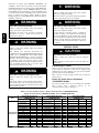
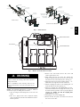
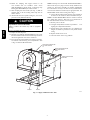
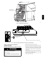
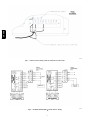
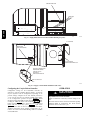
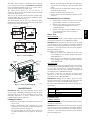
48/50HG014---028, 48/50PG20---28
Single---Package Rooftop Units
with COMFORTLinkt and Electro---Mechanical Controls
Return and Supply Smoke Detectors Accessory
Installation Instructions
PART NO. CRSMKDET001D00, CRSMKSUP001B00, CRSMKSEN001A00
TABLE OF CONTENTS
GENERAL
GENERAL . . . . . . . . . . . . . . . . . . . . . . . . . . . . . . . . . . . . . . . . 1
An HVAC (heating, ventilation and air-conditioning) system
supplies conditioned air to virtually every area of a building.
Smoke introduced into this air duct system will be distributed
throughout the entire building. Smoke detectors designed for use
inside the unit are used to sense the presence of smoke passing
through the unit.
The smoke detector utilizes photoelectric technology for the
detection of smoke. This detection method, when combined with
an efficient ducting design, samples air passing through the unit.
If sufficient smoke is sensed, an alarm signal is initiated and the
ComfortLink controls will shut down the unit. With the unit shut
down, the unit will not blow toxic smoke and fire gases
throughout the areas served by the duct system.
The return air smoke detector is part number
CRSMKDET001D00, which includes a Smoke Sensor and a
Smoke Control Module combined with sampling tube, harnesses
and hardware. The supply air smoke detector is part number
CRSMKSUP001B00, which includes a Smoke Sensor and a
Smoke Control Module combined with sampling tube, harnesses
and hardware. Part number CRSMKSEN001A00 is a Smoke
Sensor only for use as a second (Supply with existing Return, or
Return with existing Supply) Air Smoke Detector with sampling
tube, harnesses and hardware.
The Control Module can be attached to a Smoke Sensor and
installed as an assembled unit, or it can be installed separate from
a sensor. One Controller can be used to control up to two
detectors (Smoke Sensors).
SAFETY CONSIDERATIONS . . . . . . . . . . . . . . . . . . . . . . . . 1
INSTALLATION . . . . . . . . . . . . . . . . . . . . . . . . . . . . . . . . . . . 2
Check Package Contents . . . . . . . . . . . . . . . . . . . . . . . . . . . 2
Return Air Smoke Detector Installation . . . . . . . . . . . . . . . 2
Supply Air Smoke Detector Installation . . . . . . . . . . . . . . . 5
Sensor Installation . . . . . . . . . . . . . . . . . . . . . . . . . . . . . . . 7
Configuring the ComfortLinkt Controller . . . . . . . . . . . . 8
OPERATION . . . . . . . . . . . . . . . . . . . . . . . . . . . . . . . . . . . . . . 8
MAINTENANCE . . . . . . . . . . . . . . . . . . . . . . . . . . . . . . . . . . . 9
Cleaning Procedure . . . . . . . . . . . . . . . . . . . . . . . . . . . . . . 9
Recommended Service Schedule . . . . . . . . . . . . . . . . . . . . 9
Sensor Tests . . . . . . . . . . . . . . . . . . . . . . . . . . . . . . . . . . . . 9
Controller Tests . . . . . . . . . . . . . . . . . . . . . . . . . . . . . . . . . . 9
TROUBLESHOOTING . . . . . . . . . . . . . . . . . . . . . . . . . . . . . 10
Dirty LED . . . . . . . . . . . . . . . . . . . . . . . . . . . . . . . . . . . . 10
Power LED . . . . . . . . . . . . . . . . . . . . . . . . . . . . . . . . . . . . 10
Trouble LED . . . . . . . . . . . . . . . . . . . . . . . . . . . . . . . . . . 10
IMPORTANT: There are two different design revision 48/50HG
units that have been produced. Because of these differences, there
are two different versions of this accessory. This accessory
literature covers accessories manufactured for units with design
revision 1. This revision designator is found in the 13th digit of
the unit model number located on the units’ rating plate. Design
revision 0 units are not covered in this accessory book.
To determine the design revision, refer to the full unit model
number. See Fig. 1 for an example of an HG model number. The
design revision number in the model number nomenclature is
located in position 13.
SAFETY CONSIDERATIONS
Installation and servicing of air-conditioning equipment can be
hazardous due to system pressure and electrical components.
Only trained and qualified service personnel should install, repair,
or service air-conditioning equipment.
Untrained personnel can perform the basic maintenance functions
of cleaning coils and filters and replacing filters. All other
operations should be performed by trained service personnel.
When working on air-conditioning equipment, observe
precautions in the literature, tags and labels attached to the unit,
and other safety precautions that may apply.
Follow all safety codes. Wear safety glasses and work gloves. Use
care when handling and installing the accessory.
Recognize safety information. This is the safety--alert symbol
DESIGN REVISION NUMBER
Position No.
1
2
3
4
5
6
7
8
9
10
11
12
13
14
15
16
Example:
4 8 H G D 0 1 6 A A
C
6
1
1
A
A
Fig. 1 --- Model Number Chart
. When you see this symbol on the unit and in instructions or
manuals, be alert to the potential for personal injury.
C07172
1
Understand the signal words DANGER, WARNING, and
CAUTION. These words are used with the safety--alert symbol.
DANGER identifies the most serious hazards which will result in
severe personal injury or death. WARNING signifies a hazard
which could result in personal injury or death. CAUTION is used
to identify unsafe practices which may result in minor personal
injury or product and property damage. NOTE is used to
highlight suggestions which will result in enhanced installation,
reliability, or operation.
CRSMK
!
WARNING
!
FIRE HAZARD
Failure to follow this warning could cause personal
injury and/or equipment damage.
This device will not sense smoke unless the ventilation
system is operating and the cover is installed.
WARNING
WARNING
!
ELECTRICAL SHOCK HAZARD
ELECTRICAL SHOCK HAZARD
Failure to follow this warning could cause personal
injury, death and/or equipment damage.
Failure to follow this warning could cause personal
injury and/or equipment damage.
Disconnect all power to the unit before performing
maintenance or service. Install Lock Out tags on
disconnects or breakers.
For this detector to function properly, it MUST be
installed according to the instructions in this manual.
The detector MUST be operated within ALL electrical
and environmental specifications listed in this manual.
Failure to comply with these requirements may prevent
the detector from activating when smoke is present in
the air duct.
!
WARNING
FIRE HAZARD
INSTALLATION
Failure to follow this warning could cause personal
injury and/or death.
!
CAUTION
!
The National Fire Protection Association has
established that DUCT DETECTORS MUST NOT BE
USED AS A SUBSTITUTE FOR OPEN AREA
DETECTOR PROTECTION as a means of providing
life safety. Nor are they a substitute for early warning in
a building’s regular fire detection system. Carrier
supports this position and strongly recommends that the
user read NFPA Standards 90A, 72, and 101. This
smoke detector is listed per UL 268A.
EQUIPMENT DAMAGE HAZARD
Failure to follow this caution may result in equipment
damage.
When installing the smoke detector in the unit, follow all
local codes.
Check Package Contents
Remove accessory packaging and inspect shipment for damage.
If any damage is found, file a claim with the shipping agent
immediately. If any item is missing or any part does not assemble
properly, notify the Carrier distributor.
Table 1 lists the accessory package contents. Fig. 2 shows the
smoke detector.
WARNING
ELECTRICAL SHOCK AND FIRE HAZARD
Failure to follow this warning could cause personal
injury.
Return Air Smoke Detector Installation
(CRSMKDET001D00)
This device will not operate without electrical power.
Fire situations may cause an interruption of power. The
system safeguards should be discussed with your local
fire protection specialist.
The return air smoke detector is to be installed in the predrilled
holes
located
above
compressor
B1/A2
in
the
electrical/compressor section. (See Fig. 3.)
Table 1—Accessory Package Contents — Return Air Smoke Detector (CRSMKDET001D00),
Supply Air Smoke Detector (CRSMKSUP001B00), Sensor (CRSMKSEN001A00)
UNIT
RETURN SMOKE DETECTOR
CRSMKDET001D00
Description
Sensor/Controller/
Harness/Tube
Screw
Screw
Bracket
Large Bushing
Sampling Tube
Plug
48/50HG014-028,
Rubber Gasket
48/50PG20-28
Sampling Tube Collar
Wire Tie
Bushing
Harness Assy
Exhaust Tube
SUPPLY SMOKE DETECTOR
CRSMKSUP001B00
Part Number Quantity
HK61ZT001
1
AL56AU168
AL48AM397
50TG501113
HY93NH085
RN20ZT060
—
—
—
HY76TB125
HY93NH069
50TG403507
—
2
2
1
1
1
1
2
1
1
1
1
1
Description
ADDITIONAL SENSOR
CRSMKSEN001A00
Part Number Quantity
Controller/
RJ-45 Harness
Screw
Sensor Module
Tube
Cable Assy
Plug
Rubber Gasket
Sampling Tube Collar
Snap-in Wire Tie
Wire Tie
Bushing
Harness Assy
Exhaust Tube
2
Description
Part Number Quantity
HK28ZT001
1
Sensor Module
HK50ZT001
1
AL56AU168
HK50ZT001
RN20ZT008
RM91ZT015
—
—
—
HY76TB110
HY76TB125
HY93NH069
50TG403507
—
5
1
1
1
1
2
1
2
2
1
1
1
Screw
Screw
Bracket
Large Bushing
Sampling Tube
Plug
Rubber Gasket
Sampling Tube Collar
Tube
Cable Assy
Snap-in Wire Tie
Wire Tie
Cable Assy
Exhaust Tube
AL56AU168
AL48AM397
50TG501113
HY93NH085
RN20ZT060
—
—
—
RN20ZT008
RM91ZT015
HY76TB110
HY76TB125
RM91ZT001
—
1
2
1
1
1
1
2
1
1
1
5
1
1
1
Exhaust tube
Plug
Conduit nuts
( field supplied )
Rubber gasket
Sensor housing
and electronics
Sampling tube
Collar
Conduit support plate
Rubber
gasket
Terminal block cover
Cover gasket
(ordering option)
Controller housing
and electronics
Sensor cover
Cover gasket
(ordering option)
Controller cover
Conduit couplings
( field supplied )
Fastener
(2X)
Smoke Sensor
LEDs
Alarm
Trouble
Power
LEDs
C07173
Fig. 2 --- Smoke Detector
SMOKE CONTROL MODULE
PLUG LOCATION
RETURN SMOKE SENSOR
C1/B1
B1/A2
A1
Fig. 3 --- Return Air Smoke Detector Location
!
C07174
3. Remove cover from smoke detector. The screws will
remain captured in the cover.
4. Slide exhaust tube into the sensor. The exhaust tube
should be inserted from the back of the sensor, into the
hole with four slots, and locked into place. (See Fig. 2.)
5. Slide smoke detector into holes in partition with the terminal block to the right. Do not secure at this time.
6. Slide the sampling tube collar over the sampling tube until the tabs lock into the tube. (See Fig. 2.)
7. Slide long sampling tube (P/N RN20ZT060) into left-hand hole of smoke detector. It might be necessary to tilt
the smoke detector upwards in order to properly align the
sampling tube, making sure that the sampling holes
point DOWN. (See Fig. 4.)
8. Install plug into far end of sampling tube.
9. Remove the unit side panel at the return end of the unit.
Save screws for use later.
WARNING
ELECTRICAL SHOCK HAZARD
Failure to follow this warning could result in personal
injury and/or death.
Prior to installation of this accessory, make sure all
power is disconnected to the unit and locked out and
tagged.
NOTE: For horizontal applications it is easiest to install the
smoke detector prior to making duct connections.
1. Open the hinged electrical/compressor access door and
secure.
2. Find the 2 plugs located above compressor B1/A2,
remove and discard. Cut holes in the insulation located behind the partition.
3
CRSMK
Smoke Control Module
Power
Dirty
Trouble
Alarm
NOTE: This step is not needed with 48/50PG Humidi--MiZert
units because they have plug 19 harness already installed in the
control box. The harness assembly part number 50TG403507
that came with the accessory is not used. Factory installed PL--19
can be located outside the contol box by its appropriate label. For
Humidi--MiZer smoke detector wiring refer to Fig. 8.
16. Connect PL-19 from the smoke detector control module to
the PL-19 on the control box harness installed in Step 15.
NOTE: On 48PG Humidi--MiZer units the control box harness
has a jumper plug attached. This needs to be disconnected so
PL--19 from the smoke detector can be snaped in.
17. Restore power to the unit.
18. Configure ComfortLink controller as specified in
Configuring the ComfortLink Controller.
19. Perform Sensor and Controller tests. At a minimum, the
Magnet test should be performed to verify smoke detector
wiring.
20. Replace smoke detector cover.
21. Check for alarms. Correct any problems.
10. Mount the sampling tube support bracket to the
cross member with two 1/4AB-14 5/8-in. screws
(P/N AL48AM307) as shown in Fig. 5. Insert large snap
bushing (P/N HY93NH085) into hole in bracket.
11. Slide sampling tube into bracket. (See Fig. 4.) Pull the
sampling tube so that the locking collar snaps into the
smoke detector.
12. Attach smoke detector to partition using two, 8-18 3/4-in.
pan head screws (P/N AL56AU168).
!
CAUTION
EQUIPMENT DAMAGE HAZARD
Failure to follow this caution may result in equipment
damage.
CRSMK
Do not overtighten the screws.
13. Replace the unit side panel.
14. Install the snap bushing (P/N HY93NH069) in the center
knockout underneath the control terminal strips located in
the bottom right-hand corner of the control box.
15. Feed wires through snap bushing and connect to appropriate terminals as shown in Fig. 6 for ComfortLinkt units
or Fig. 7 for Electro--Mechanical units.
INSTALL SUPPLY SENSOR TUBE
WITH HOLES POINTING
UP
INSTALL RETURN SENSOR TUBE
WITH HOLES POINTING
DOWN
INSTALL RETURN EXHAUST
TUBE HERE
BRACKET
BUSHING
Fig. 4 --- Supply and Return Sensor Tube
4
C07175
CRSMK
SAMPLING TUBE
SUPPORT BRACKET
Fig. 5 --- Sampling Tube Support Bracket
C07176
PL19
CUT OFF CONNECTOR, LABELED TB3-5, ON ORN WIRE
Fig. 6 --- Return and Supply Air Smoke Detector Wiring on ComfortLink Units
Supply Air Smoke Detector Installation
(CRSMKSUP001D00)
1. Open the indoor fan access door and secure.
2. Open and secure hinged electrical/compressor access door.
3. Disconnect wires located on the right-hand side of the fan
deck. On gas heat units, the indoor fan plug and the limit
switch quick connects must be disconnected. On units
without gas heat, only the indoor fan plug must be
disconnected.
4. Find the 2 plugs located in the blower side plate. Remove
the plugs and discard. It will be necessary to remove some
of the tape holding the plugs in place.
5. Remove cover from smoke detector. The screws will
remain captured in the cover.
The supply air smoke detector is to be installed in the predrilled
holes located on the front of the first indoor blower. (See Fig. 9.)
!
C07177
WARNING
ELECTRICAL SHOCK HAZARD
Failure to follow this warning could result in personal
injury and/or death.
Prior to installation of this accessory, make sure all
power is disconnected to the unit and locked out and
tagged.
5
CRSMK
Fig. 7 --- Smoke Detector Wiring on Electro--Mechanical Control Units
Fig. 8 --- 48/50PG Humidi--MiZert Smoke Detector Wiring
6
C07178
C07179
!
CAUTION
EQUIPMENT DAMAGE HAZARD
Failure to follow this caution may result in equipment
damage.
Sensor Installation (CRSMKSEN001A00)
Do not overtighten the screws.
When adding return smoke sensor to previously installed supply
smoke detector:
1. Open electrical/compressor section access door/panel.
2. Disconnect PL-19 from control module to terminal strip
by separating plug connectors.
3. Remove control module cover. Disconnect supply sensor
RJ-45 wire from control module.
4. Remove three screws attaching control module to compressor partition and save screws for later use.
5. Remove control module from unit.
6. Slide feet of control module into receptacle on the return
sensor housing and secure from the backside using one
screw removed in Step 4. The J1 RJ-45 connector on sensor should be nearest the control module. Knockout holes
should align. (See Fig. 11.)
7. Route short RJ-45 wire from J1 connector of sensor,
through knockout holes, and connect to J1 connector of
control module.
8. Follow steps 2-20 of instructions for installing return
smoke detector.
IMPORTANT: Step 15 requires connecting the supply smoke
sensor RJ--45 wire to connector J2 in the control module.
When adding supply smoke sensor to previously installed return
smoke detector:
Follow steps 1-14 and 19-29 from supply smoke detector
installation instructions.
13. Attach cable to fan side plate using snap-in wire ties.
See Fig. 9 for clarification. Secure to center post.
14. Secure cable to back side of cable tray using three snap-in
wire ties.
15. In the Electrical/Compressor section, install snap bushing
in the center knockout underneath the terminal strips located in the bottom right-hand corner of control box.
16. Connect wires to terminal strips as shown in Fig. 6 for
ComfortLinkt units or Fig. 7 for Electro--Mechanical
Units.
NOTE: This step is not needed with 48/50PG Humidi--MiZert
units because they have plug 19 harness already installed in the
control box. The harness assembly part number 50TG403507
that came with the accessory is not used. Factory installed PL--19
can be located outside the contol box by its appropriate label. For
Humidi--MiZer smoke detector wiring refer to Fig. 8.
17. Remove cover from control module and remove knockout
from side of module nearest the RJ-45 connector.
18. Using
three
8-18 3/4-in.
pan
head
screws
(P/N AL56AU168) screws, secure control module to compressor partition above compressor B1/A2 location.
19. Connect PL-19 from control module to PL-19 from wiring harness installed in Step 16.
NOTE: On 48PG Humidi--MiZer units, the control box harness
has a jumper plug attached. This needs to be disconnected so
PL--19 from the smoke detector can be snapped in.
7
CRSMK
20. Route cable from supply smoke sensor, along the outside
of the control box, through the control module knockout
and connect to the J1 RJ-45 connector.
21. Using wire ties, secure the wiring so it does not interfere
with unit operation.
22. Replace control module cover.
23. Restore power to the unit.
24. Configure ComfortLink controller as specified in Configuring the ComfortLink Controller below.
25. Perform Sensor and Controller tests. At a minimum, the
Magnet test should be performed to verify smoke detector
wiring.
26. Turn off power to the unit.
27. Reconnect the indoor fan plug and the limit switch wires if
applicable.
28. Close the indoor fan section door.
29. Restore power to the unit and check for alarms. Correct
any problems encountered.
30. Close Electrical/Compressor section door.
6. Slide the sampling tube collar over the sampling tube
until the tabs lock into the tube.
7. Slide sampling tube into smoke detector with eight slots.
Make sure sampling tube holes are aligned facing UP.
8. Insert plug into far end of the sampling tube.
9. Place rubber gaskets over each sampling tube on smoke
detector. (See Fig. 2.)
10. Remove one knockout from top of smoke detector.
11. Insert one end of RJ-45 wire harness through knockout
and wire to smoke detector as shown in Fig. 10.
12. Slide smoke detector into holes in fan side plate with
the terminal block at the top and secure using two,
8-18 3/4-in. pan head screws (P/N AL56AU168). Replace
cover.
SMOKE DETECTOR
CRSMK
WIRE TIES
C07180
Fig. 9 --- Supply Smoke Detector Location and Wire Routing (Top View)
RJ-45 HARNESS
INSTALL CONTROL
MODULE HERE
USING THREE SCREWS
CUT TAPE BEFORE
INSERTING SMOKE DETECTOR.
ROUTE RJ-45 HARNESS ALONG
SMOKE POWER HARNESS
THRU BOX, AND OUT
AS SHOWN TO
SUPPLY SMOKE DETECTOR
PUNCH OUT KNOCK OUT
PLUG
Fig. 10 --- Supply Control Module Installation (Side View)
C07181
OPERATION
Configuring the ComfortLinkt Controller
Configuration settings for the ComfortLink controller are
changed by using the Scrolling Marquee display. A password
may be required to edit the configurations, depending on the
previous settings configured in the unit. Default password is
“1111.” Use the arrow keys to scroll the red LED on the display
to the “Configuration” position and press ENTER . Scroll
through the menu until UNIT is found and press ENTER . After
reaching the UNIT sub-menu, scroll to FS.SW (Fire Shutdown
Input) and press ENTER twice, change the value to 1 (Normal
Open) with the arrow keys, press ENTER again. Press
ESCAPE three times to return to the top level of the menu.
Additional information about changing configurations can be
found in the Control and Troubleshooting Guide for 48/50HG
and 48/50PG units.
!
CAUTION
EQUIPMENT DAMAGE HAZARD
Failure to follow this caution may result in damage to the
unit.
The smoke detector must be tested and maintained regularly
following NFPA 72 requirements. The smoke detector
should be cleaned at least once a year.
8
The smoke detector contains a photoelectric detector approved
for an extended air speed range of 100 to 4000 feet per minute
and an operational temperature range of -4_ to 158_F. Do not
operate the smoke detector out of these ranges.
The smoke detector operates on 24 vac, 120 vac, or
220/240 vac. The thermostat power terminals on the unit are used
to power the smoke detector.
The cover of the controller contains the Alarm, Trouble, Dirty
and Power LEDs. The cover of the sensor contains the Alarm,
Trouble and Power LEDs. (See Fig 2.)
The smoke detector can be reset by a momentary power
interruption, by the reset button on the front cover, by the control
panel, or by the remote reset accessory.
Recommended Service Schedule
S Visually inspect each sensor connected to the controller
S
Perform a sensor alarm test on each sensor connected
to the controller upon installation and once every
12 months thereafter.
J1
J1
S
Perform a sensor dirty test upon installation and once
every 6 months thereafter or more frequently, as
conditions warrant.
J2
E
Sensor Tests
Sensor Alarm Test
The sensor alarm test checks a sensor’s ability to signal an alarm
state. This test requires the use of a SD-MAG test magnet.
IMPORTANT: This test places the duct detector into the alarm
state. Unless part of the test, disconnect all auxiliary equipment
from the controller before performing the test. If duct detector is
connected to a fire alarm system, notify the proper authorities
before performing the test.
To perform a sensor alarm test:
1. Hold the test magnet where indicated on the side of the
sensor housing for seven seconds. Verify that the sensor’s
Alarm LED turns on.
2. Reset the sensor by holding the test magnet against the
sensor housing for two seconds. Verify that the sensor’s
Alarm LED turns off.
Sensor Dirty Test
The sensor dirty test provides an indication of the sensor’s ability
to compensate for gradual environmental changes. A sensor that
can no longer compensate for environmental changes is
considered 100% dirty and requires cleaning or replacing. This
test requires the use of a SD-MAG test magnet.
To perform a sensor dirty test, hold the test magnet where
indicated on the side of the sensor housing for seven seconds.
Verify that the sensor’s Dirty LED flashes.
IMPORTANT: Holding the test magnet against the sensor
housing for longer than 7 seconds will put the duct detector into
the alarm state and activate all automatic alarm responses.
The sensor’s Dirty LED indicates the results of the dirty test as
shown below.
CONTROL MODULE
RETURN SENSOR
J1
J1
J2
E
S
SECURE FROM BEHIND
WITH SCREW
TERMINAL STRIP
C07182
Fig. 11 --- Sensor Installation
HVAC duct
Sampling
tube
Sensor
housing
Optic
plate
Airflow
Retainer
clip
Optic
housing
Fig. 12 --- Sensor Cleaning Diagram
C07183
FLASHES
MAINTENANCE
IMPORTANT: Notify the proper authorities that the smoke
detector system is undergoing maintenance, and that the system
will temporarily be out of service. Disable the zone or system
undergoing maintenance to prevent unwanted alarms and
possible dispatch of the fire department.
DESCRIPTION
1
0 to 25% dirty. This is typical on a newly installed duct
detector.
2
3
4
26 to 50% dirty
51 to 75% dirty
76 to 99% dirty
Controller Tests
Cleaning Procedure
Controller Alarm Test
The controller alarm test checks the controller’s ability to initiate
and indicate an alarm state.
IMPORTANT: This test places the duct detector into the alarm
state. Unless part of the test, disconnect all auxiliary equipment
from the controller before performing the test. If duct detector is
connected to a fire alarm system, notify the proper authorities
before performing the test.
1. Disconnect power from the duct detector then remove the
sensor’s cover.
2. Using a vacuum cleaner, clean compressed air, or a soft
bristle brush, remove loose dirt and debris from inside the
sensor housing and cover. (See Fig 12.)
Use isopropyl alcohol and a lint-free cloth to remove dirt
and other contaminants from the gasket on the sensor’s
cover.
9
CRSMK
upon installation and once every 6 months thereafter.
CONTROL MODULE
RETURN SENSOR
S
3. Squeeze the retainer clips on both sides of the optic housing then lift the housing away from the printed circuit
board.
4. Gently remove dirt and debris from around the optic plate
and inside the optic housing.
5. Replace the optic housing and sensor cover.
6. Connect power to the duct detector then perform a sensor
alarm test.
To perform a controller alarm test:
1. Press the controller’s test/reset switch for seven seconds.
Verify that the controller’s Alarm LED turns on.
2. After performing a controller alarm test, reset the sensor
by pressing the test/reset switch for two seconds. Verify
that the controller’s Alarm LED turns off.
Controller Dirty Test
The controller dirty test checks the controller’s ability to initiate a
sensor dirty test and indicate its results.
To perform a sensor dirty test, press the controller’s test/reset
switch for two seconds. Verify that the controller’s Trouble LED
flashes.
TROUBLESHOOTING
CRSMK
Dirty LED
Sensor’s Dirty LED is Flashing
Clean the sensor assembly as described in Cleaning Procedure.
Power LED
Sensor’s Power LED is OFF
1. Check the controller’s Power LED. If it is off, determine
why the controller does not have power and make the
necessary repairs.
2. Check the wiring between the sensor and the controller. If
wiring is loose or missing, repair or replace as required.
Controller’s Power LED is OFF
1. Make sure the circuit supplying power to the controller is
operational. If not, make sure JP2 and JP3 are set correctly
on the controller before applying power.
Copyright 2007 Carrier Corp. S 7310 W. Morris St. S Indianapolis, IN 46231
2. Verify that power is applied to the controller’s supply input terminals. If power is not present, replace or repair wiring as required.
Trouble LED
Controller’s Trouble LED is On
1. Check the Trouble LED on each sensor connected to the
controller. If a sensor’s Trouble LED is on, determine the
cause and make the necessary repairs.
2. Check the wiring between the sensor and the controller. If
wiring is loose or missing, repair or replace as required.
Controller’s Trouble LED is Flashing
1. One or both of the sensors is 100% dirty. Determine which
sensor’s Dirty LED is flashing.
2. Clean the sensor assembly as described in Cleaning
Procedure.
Sensor’s Trouble LED is On
1. Check the sensor’s Dirty LED. If it is flashing, the sensor
is dirty and must be cleaned.
2. Check the sensor’s cover. If it is loose or missing, secure
the cover to the sensor housing.
3. Replace sensor assembly.
Sensor’s Trouble LED is On But Controller’s Trouble LED is
Off
Remove JP1 on the controller.
Printed in U.S.A.
Edition Date:7/07
Manufacturer reserves the right to change, at any time, specifications and designs without notice and without obligations.
10
Catalog No:48/50H,P---24SI
Replaces:48/50H,P--- 10SI