1
GENERAL
CRSMK
These instructions cover the installation of a return,
supply or both smoke detectors in rooftop equipment from
15 to 25 tons. These apply to Gas-- Electric,
Electric-- Electric and Heat Pump versions. The chart
below outlines the quantities required depending on the
desire for which option is needed.
CRSMKKIT002A00
CRSMKSEN002A00
Return Smoke
1
1
Supply Smoke
1
1
Return and Supply
Smoke
1
2
The primary intent of these detectors is to shut down the
unit’s air delivery services upon an alarm trip. They are
not designed as a substitute for an open area smoke
detector nor a substitute for early warning detection or a
replacement for a building’s regular fire detection system.
Smoke detectors are not designed to detect toxic gases
which can build up to hazardous levels in some fires.
These devices will not operate without electrical power.
As fires frequently cause power interruptions, it is
recommended that the installer further safeguards with
your local fire protection specialist and code enforcement
agency.
For installations using two sensors, the duct smoke
detector does not differentiate which sensor signals an
alarm or trouble condition. The sensor uses a process
called differential sensing to prevent gradual
environmental changes from triggering false alarms. A
rapid change in environmental conditions, such as smoke
from a fire, causes the sensor to signal an alarm state but
dust and debris accumulated over time does not.
Air is introduced to the duct smoke detector’s sensing
chamber through a sampling tube that extends into the
HVAC duct and is directed back into the ventilation
system through an exhaust tube. The difference in air
pressure between the two tubes pulls the sampled air
through the sensing chamber. When a sufficient amount
of smoke is detected in the sensing chamber, the sensor
signals an alarm state and the controller automatically
takes the appropriate action to shut down fans and
blowers, change over air handling systems, notify the fire
alarm control panel, etc.
!
EQUIPMENT DAMAGE HAZARD
Failure to follow this caution may result in damage to
equipment.
Excess temperature differentials between the ambient
air and the sampled air can produce unwanted
condensation inside the sensor, which may cause the
sensor to function improperly. Precautions should be
taken to limit the temperature range and the amount of
condensation to which the sensor is exposed.
DESCRIPTIONS
Controller
The controller includes a controller housing, a printed
circuit board, and a clear plastic cover. The controller can
be connected to one or two compatible duct smoke
sensors. The clear plastic cover is secured to the housing
with a single captive screw for easy access to the wiring
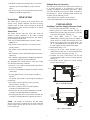
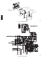
terminals. (See Fig. 1, 3, and 4.)
Sensor
The sensor includes a plastic housing, a printed circuit
board, a clear plastic cover, an exhaust tube, and a
sampling tube. The exhaust tube and sampling tube are
attached during installation. The sampling tube varies by
size, but the correct one is included with the kit. The
clear plastic cover permits visual inspections without
having to disassemble the sensor. The cover attaches to
the sensor housing using four captive screws and forms an
airtight chamber around the sensing electronics.
System
The smoke detector comprises a controller and one or two
sensors. Its primary function is to shut down the rooftop
unit in order to prevent smoke from circulating throughout
the building. It is not to be used as a life saving device.
When these smoke detectors are factory installed on the
units listed above, no additional sampling tubes are
required to be field installed. (See Fig. 5.)
The controller is designed for multiple operating voltages
and provides relay contacts for connection to fire alarm
systems, HVAC controls, and other auxiliary functions. A
remote test/reset station can be connected to the controller
to provide these functions.
CAUTION
FEATURES
The smoke sensor incorporates the following features:
S Environmental compensation with differential sensing
for reliable, stable, and drift-- free sensitivity.
S Magnet-- activated test/reset switch on sensors.
S PCB mounted photoelectric sensor with on-- board
intelligence.
S Cover tamper switch for added security.
S Alarm, Trouble, Dirty, and Power status LEDs. (See
Table 1 and Fig. 3.)
S Extended temperature and air velocity ranges.
S Capable of adding an additional sensors (for a total of
two) using the same controller.
S Multiple operating voltages.
S No tools required to access field connection terminals.
S Recessed momentary switch for test/reset of the
detector.
S One set of normally open alarm initiation contacts for
connection to an initiating device circuit on a fire alarm
control panel.
S Two Form-- C auxiliary alarm relays for interface with
rooftop unit or other equipment.
2