1
[05]DISASSEMBLYANDASSEMBLY.fm 14 ページ 2004年4月19日 月曜日 午後1時38分
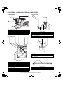
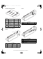
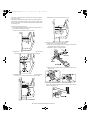
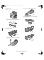
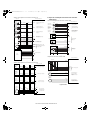
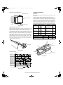
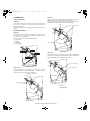
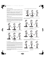
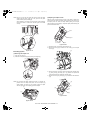
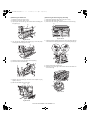
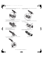
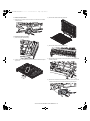
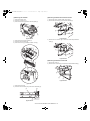
g. Decolor roller
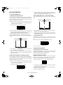
1) Remove the frame unit.
2) Remove the E-ring, the gear, and the bearing. Remove the decolor
roller.
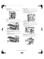
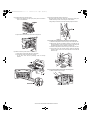
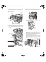
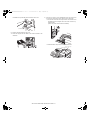
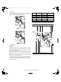
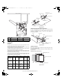
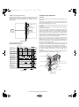
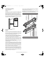
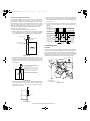
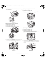
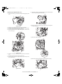
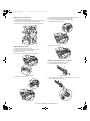
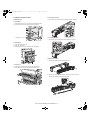
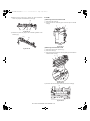
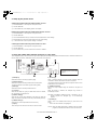
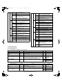
7) Pull out the transport unit to the copier unit guide.
8) Remove the docking unit connector, and pull it out.
copier unit guide
8
7
*
When removing or attaching the roller, be careful of the actuator.
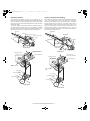
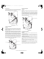
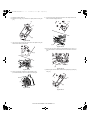
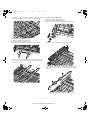
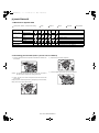
b. Paper entry sensor 1
1) Remove the paper entry sensor 1, and remove the connector.
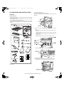
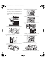
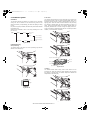
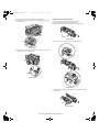
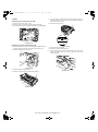
(2) Interface transport unit
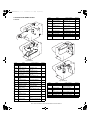
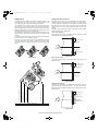
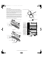
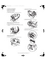
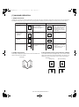
a. Docking unit
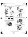
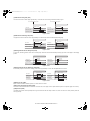
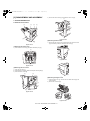
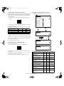
1) Remove the screw, and slide the upper cover as shown in the figure.
2) Remove the screws C from the upper side of the front cover, and
remove the front cover and the docking unit.
3) Remove the two screws and remove the front cover.
4) Remove the four screws, and remove the left cover.
2
1
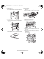
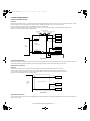
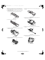
c. Photo sensor
4
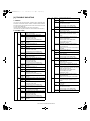
1) Remove the photo sensor, and remove the connector.
3
5) Open the transport unit cover.
6) Remove the two screws A (M4 x 10).
d. Paper entry sensor 2
1) Remove the paper entry sensor 2, and remove the connector.
6
5
6
AR-F14/PN1 DISASSEMBLY AND ASSEMBLY 5-14