1
ION CANNON ION GENERATOR KIT
Ramsey Electronics Model No.
IG7
Have you ever wondered how those ion air cleaners work? Ever
wonder why the air smells so fresh after a thunderstorm? This
instructional manual takes you through several ion related
experiments that you can play with to see for yourself how
amazing ions are, their health benefits, and health risks. Also
make a working air cleaner for the water closet when done!
•
ION power supply with adjustable control for a clean source of
high voltage DC. Not a pulsed output like some so-called ION
supplies.
•
ION supply capable of delivering 7.5 kV with 400 uA max current
output.
•
Runs from 10V to 18VDC while drawing about 350 mA or less; run
from a battery for portable use or in the car.
•
Waterproof casing; no assembly of high-voltage portion
necessary!
•
Great for science fairs, high energy capacitor charging, and many
experiments requiring “static” voltages.
•
•
Perfect for exciting Van Degraff generator belts!
Includes circuit board for making your own ion wind generator.
DANGER
HIGH VOLTAGE
See instruction manual before operation
IG7 Page 1
RAMSEY TRANSMITTER KITS
• FM100B Professional FM Stereo Transmitter
• FM25B Synthesized Stereo FM Transmitter
• MR6 Model Rocket Tracking Transmitter
• TV6 Television Transmitter
RAMSEY RECEIVER KITS
• FR1 FM Broadcast Receiver
• AR1 Aircraft Band Receiver
• SR2 Shortwave Receiver
• SC1 Shortwave Converter
RAMSEY HOBBY KITS
• SG7 Personal Speed Radar
• SS70A Speech Scrambler
• BS1 “Bullshooter” Digital Voice Storage Unit
• AVS10 Automatic Sequential Video Switcher
• WCT20 Cable Wizard Cable Tracer
• LABC1 Lead Acid Battery Charger
• ECG1 Electrocardiogram Heart Monitor
• LC1 Inductance-Capacitance Meter
RAMSEY AMATEUR RADIO KITS
• DDF1 Doppler Direction Finder
• HR Series HF All Mode Receivers
• QRP Series HF CW Transmitters
• CW7 CW Keyer
• CPO3 Code Practice Oscillator
• QRP Power Amplifiers
RAMSEY MINI-KITS
Many other kits are available for hobby, school, Scouts and just plain FUN. New
kits are always under development. Write or call for our free Ramsey catalog.
IG7 ION CANNON KIT MANUAL
Ramsey Electronics publication No. MIG7 Revision 1.1
First printing: December 2001 MRW
COPYRIGHT 2001 by Ramsey Electronics, Inc. 590 Fishers Station Drive, Victor, New York
14564. All rights reserved. No portion of this publication may be copied or duplicated without the
written permission of Ramsey Electronics, Inc. Printed in the United States of America.
IG7 Page 2
Ramsey Publication No. MIG7
Price $5.00
KIT ASSEMBLY
AND INSTRUCTION MANUAL FOR
IG7 ION CANNON ION GENERATOR KIT
TABLE OF CONTENTS
Safety Guidelines .................................4
Ion Theory .............................................6
Learn As You Build .............................13
Parts List .............................................15
Assembly .............................................16
Parts Layout ........................................20
Schematic............................................21
Experiments ........................................22
Troubleshooting ..................................29
Conclusion...........................................30
Warranty ..............................................31
RAMSEY ELECTRONICS, INC.
590 Fishers Station Drive
Victor, New York 14564
Phone (585) 924-4560
Fax (585) 924-4555
IG7 Page 3
SOME SAFETY NOTES WITH THE IG7
Even though 7.5 kV sounds like a lot of voltage, and it is in relation to most
other circuitry today, it is not necessarily lethal. What is dangerous about high
voltage is the ability of a high voltage source to deliver current, whether it be a
quick impulse of high current like a lightning strike, or a long term source like a
high voltage power supply. It is generally accepted that you need at least 1 mA
of current flowing through a person’s body to kill them, though a person’s health
has a large role to play in this. If you are at all in question about your health or
have heart problems, please follow the safety guide at the end of this chapter!
The IG7 has the capability to deliver about 400 uAmps (0.4 mA) of current.
This is a bit less than the 1 mA previously mentioned, but still close enough to
hurt a lot! Just ask one of our employees who pointed to the high voltage
terminal and discovered what this project was the hard way! While the actual
electrocution may not be what injures you, it can be the secondary reaction,
such as falling out of your chair and injuring yourself in the fall. I have
personally flown across a room when I was experimenting with a larger supply
and had no recollection of how I put a dent in my parent’s washing machine!
What I am trying to say here is that this is a relatively safe project, but there
are certainly some precautions you must take to ensure an enjoyable
experience, as well as a long life! Our fellow employee lived through it; so
should you. Personally I have yet to be electrocuted by this little gem, and I
don’t care to be in the future. Any time I am around high voltage I make sure I
am not tired, I don’t take it for granted, and I am aware of the possible
consequences.
Some basic rules around this kit:
•
Always use only one hand. The easiest way to do this is to keep the other
hand in your pocket. This reduces the chances of current flow across your
heart. I would rather have a tingly leg than see wings sprout from my back
on the way to cloud 9.
•
Always unhook the power before working on anything. Don’t trust the power
switch, as many power supplies have enough capacitance to keep things
running for quite a while after the power is turned off. Also wait a few
seconds before reaching for the unit.
•
Use a grounding wire to discharge any high voltage terminals before
handling the device. By grounding I mean solder a wire to the black lead of
the high voltage power supply, then touch the high voltage terminal
connection with the other end of the wire. This will discharge any stored
potential by shorting the output to ground. Many high voltage devices can
maintain a charge for WEEKS after the power has been removed.
IG7 Page 4
•
NEVER EVER! charge capacitors unless you honestly know what you are
doing! This increases the danger level astronomically! Even a small high
voltage capacitor when charged can deliver more than enough current to
kill or injure you!
•
Keep a clean workbench. Having a clutter of wires around can confuse
you as to which ones are actually grounded, and which ones you may use
to try and discharge the high voltage terminal.
•
Keep in mind that sensitive electronic equipment can be permanently
harmed by the high voltage ions which this kit produces. Ions travel freely
in the air and will accumulate on components at a distance. These ions
have the potential to damage computers, calculators, portable phones,
and other vulnerable electronics devices. If in question, keep these
sensitive items in a different room or as far away as possible from this unit
while you are experimenting with it.
IG7 Page 5
ION THEORY
What are ions you may ask, are they protons or electrons? Actually they are
neither one, at least not electrons by themselves. An ion is a charged molecule like that of a particle of smoke which either has one or more electrons removed, or one or more extra electrons added giving it the ability to carry a
charge of electricity.
Asbestos
Rabbit Fur
Acetate
Glass
Mica
Human Hair
Nylon
Wool
Fur
Lead
Silk
Aluminum
Paper
Cotton
Steel
Wood
Amber
Sealing Wax
Hard Rubber
MYLAR
Nickel
Copper
Silver
UV Resist
Brass, SS
Gold, Platinum
Sulfur
Acetate Rayon
Celluloid
Orlon
Acrylic
SRAN
Polyurethane
Polyethylene
Polypropylene
Rubber Balloon
PVC (Vinyl)
Silicon
Teflon
Silicone Rubber
More Positive
Neutral
Imagine rubbing a balloon on your head; we’re
making the assumption there’s a little hair up
there! The resulting static that accumulates on
the balloon will have a negative charge as seen
by looking at the Triboelectric series chart. This
chart shows us how materials gain or loose electrons when brought in contact and then removed
from one another. We can see that human hair
is more positive than the rubber balloon, so the
hair winds up loosing electrons while the rubber
balloon gains them. The balloon now becomes a
very large negative “ion” in the sense that it carries a net electrically negative charge.
Now try and stick the balloon to the ceiling.
When you bring the balloon closer and closer to
the surface of the ceiling, its negative charge
begins repelling electrons from the surface of
the ceiling. The lack of electrons near the surface will give that area of the ceiling a net positive charge. Now when the balloon touches the
ceiling, the attractive force between the balloon
and the ceiling is enough to suspend the balloon! This inductive process allows you to use
one charged object to induce a charge in another!
One thing you might expect with the prior experiment is that since the balloon and the ceiling are
touching, the electrons would rapidly transfer
and neutralize the charge. This isn’t the case
however. The electrons are prevented from doing so by the thin layer of air between the balloon and the ceiling. This experiment won’t work
as well in humid conditions because the air becomes more conductive with the additional water
More Negative
vapor. Increased humidity allows the electrons
to migrate through the air and neutralize the
Triboelectric Series
charge even faster. This type of electron moveIG7 Page 6
ment through the air is called ‘ionic flow’.
Instead of the electron from the balloon floating through the air all by itself, it
is “grabbed” by a passing neutral air molecule. The air molecule acquires a
negative charge which is the same as the balloon that has not yet lost all of it’s
electrons. Since these charges are alike, they repel. Given that the air molecule is mobile, it moves away from the like charged balloon along with the extra electron. The positive charge on the ceiling close by causes the air molecule to become attracted to it. The closer the molecule gets to the ceiling, the
more attractive force becomes on it. Suddenly the molecule bumps into the
surface of the ceiling where there is a paint particle with a missing electron.
The air molecule “hands off” the extra electron and continues on its random
way with its now neutral charge and the paint particle on the ceiling as a result
becomes neutrally charged as well.
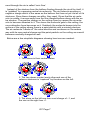
Below are a few simplistic diagrams showing how ions are created:
1. Two atoms in their neutral states.
2. The two atoms contact each other and one of the
valence electrons is “captured” by the atom on the left.
3. The atom on the left now has a net charge of –1, and
the one on the right has +1.
IG7 Page 7
The previous diagrams show how ions are created by contacting two atoms
together and thereby handing off an electron. If these atoms were mobile like
in a gas or liquid, the different charges would attract each other very quickly
and neutralize again. They wouldn’t get very far at all unless the atoms had
enough velocity to overcome the electrical attraction. If these atoms were rubber and hair, like in our balloon example, the motion of physical separation
would draw these two particles apart and create two oppositely charges particles or ions.
The problem of getting ions into the air is that you have to have enough voltage gradient to initiate the electron exchange. A voltage gradient indicates
lines of equal voltage potential the same way isobars indicate lines of equal air
pressure on your weather-mans’ weather map. A strong voltage gradient
would have a lot of lines in a small area. This indicates a strong electrical field
where ions will probably be able to flow. Similarly a strong air pressure gradient indicates there will be a lot of wind.
Some atoms and molecules are easier to ionize than others. This is dependant upon how strongly the atom or molecule is holding on to its electrons. If
they are loosely bound, they will loose them easily and allow us to ionize the
gas much easier. Some gasses make excellent insulators because they
strongly hold onto their electrons. Others like Hydrogen and Helium have a
loose grip on their electrons and make for poor insulators. Thus they are excellent sources of light when they are ionized, like in a laser.
To assist in allowing gasses to ionize, we can lower the pressure of the gas.
Higher pressure gasses don’t ionize as easily as low pressure gasses because the proximity of one gas molecule to another. If gas molecules are
tightly packed together, the motion of the gas molecules keep knocking electrons back into place. Space the molecules out a bit more and there isn’t
enough motion to knock electrons back into place. They instead begin to roam
around the gas and excite more molecules into ions.
Mixing of gasses together even has more impact on how easily ions are
formed. For example Helium and Hydrogen mixed together in the right portions will ionize easier than either one by themselves. Mixing water vapor into
your standard atmospheric gas mixture allows ions to flow very easily. Water
vapor is very good at transporting charges due to the nature and geometry of
the water molecule. We will leave further details up to the chemistry books!
In our case we need to get ions into the air at all times so we’ll need to have
plenty of voltage. The IG7 has plenty with its 7.5 kV output! In fact with normal
dry air we only need about 3,000 Volts per millimeter to get the air to begin to
ionize. Another factor to consider to get electrons in the air is the type of high
voltage terminal to use. Due to repulsive forces we can change our terminal
shape to better suit our purpose. To release ions, we want a sharp tip. To prevent them from being lost we will use a rounded tip. Why is this?
IG7 Page 8
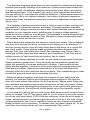
The diagram below shows a conductive tear-shaped object with a high voltage field around it. The lines are called equipotential lines and they indicate
our voltage gradient potential as we mentioned before. A rounded tip will disperse the gradient over a larger area than that of a sharp tip. Notice below that
the gradient on a rounded tip isn’t very steep while the sharper tip is. In actuality, the sharper the tip the steeper the gradient is; also the distortion in the gradient lines makes it easier to “bleed” off ions into the air. The bleeding off of
ions is called the corona effect.
Sharp Tip Gradient
Rounded Tip Gradient
To estimate how concentrated and electrical field will be around a given
shape and determine how good of an insulator or conductor to the air it is involves a little geometry. You can draw tangents to the curved surface at intervals of say 10 degrees of arc. Remember what a tangent to an arc is? It is a
line that only intersects at one point on the arc and is at an exact right angle to
a line drawn from the center of the arc to the tangent (also called the ray). A
slow smooth arc, like the right hand side of the diagram, involves very few tangents at 10 degree intervals. A sharp point would need many. If you look at
the previous diagram, you can see that the sharp points’ angle looks to be
around 315 degrees from the outside when we figure the metal is 45 degrees
of angle or so. This would take 315 / 10 = 31.5 tangential lines to reproduce.
The entire rest of the surface would only need the remaining 45 degrees or
45 / 10 or 4.5 tangents.
If you went in microscopically and looked at a well sharpened tip, it would
not appear to be as sharp as you may think. Ideally you would like to have a
perfectly sharp tip, but that is unlikely. When we make our ion wind generator,
you will be able to see the effect of a very sharp tip vs. a dull one rather well.
Air Ions and their effects
Ions have always been touted as being one of the best methods of cleaning
the air of dust and pollen as well as stimulating the cilia in your lungs to accelerate the removal of foreign debris. This tends to be a little more complicated
than simply generating ions.
IG7 Page 9
When air is ionized during the corona effect, you will see a sharp point of
purple on the end of the metal tip. This indicates that air is either being
stripped of electrons or electrons are being added to the air. The process
emits some light as the electrons are moved about due to them jumping valences in the gas molecule. The problem is when air becomes highly ionized,
it also can become quite reactive as well. This means that the Nitrogen in the
air can combine with Oxygen to form Nitric Oxide (NO), and Oxygen to form
Ozone (O3). Both of these components are very reactive, and in large quantities can do a lot of harm to your lungs.
Usually in a device such as this, the quantity of Ozone generated is very low
and Nitrous Oxide is almost undetectable. We will work to reduce the Ozone
to a very low level to where it isn’t a heath risk at all. Ozone counteracts any
benefits that we may get from negative ions, so ideally we would like to get rid
of the Ozone product altogether. Ozone does however have its benefits. It reacts with most odors in the air and will neutralize them as well as killing most
airborne viruses and bacteria. This factor can be quite helpful in a bathroom,
animal room, or near garbage cans.
To reduce the Ozone generated we will try and get a good balance between
the amount of air we will ionize and the amount of ions we want to bleed off.
We do this by sharpening the tips of our electrodes and adding enough electrode elements that it effectively reduces the supply voltage to the bare minimum to ionize the air. The steeper the voltage gradient is, the better the
chances of creating Ozone from the fact that air will become heavily ionized
within this gradient. We are going to reduce the steepness of the gradient by
using a very sharp point and reducing the terminal voltage due to loading.
Another thing that amplifies how much Ozone is produced is the type of ion
that we are creating. Positively ionized air creates Ozone at a much greater
rate than negatively ionized air. This is part of the reason why our supply will
be generating negative ions instead of positive ones. It is also rumored that it
is negative ions which have most of the heath benefits.
Keep in mind that ions in the air can transfer a great amount of voltage and
current invisibly to all sorts of surfaces. Air movement from fans and open windows can move strongly charged air on its way to sensitive components.
Imagine the surface of a chip inside of your nice new computer whose nonconductive surface acts like a capacitor to the conductive material inside. The
charge from air ions sticking to it builds up over time to the point that it discharges to one of the leads and destroys the device!
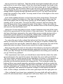
As air ions move, they loose some of their energy. The amount of energy
that is lost completely depends on how strong the originating terminal voltage
was that generated it. For example a 100 kV terminal may be able to transfer
some ions up to 10 feet away and still have a potential of 20 kV! 20 kV is a lot
to a circuit that can only take a discharge voltage of 1 kV, a common specifiIG7 Page 10
cation. In our case the terminal will be around 3 to 5 kV with the IG7. How do
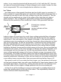
we reduce the potential energy of these charged ions to make it safer for electrical components? We use a simple device called an ion tube.
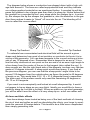
Ion Tubes
Ion tubes serve a few special functions and are luckily easy to construct. A
tube consists of a grounded piece of conductive tubing with a sharp pin that is
centered at one end to emit the high voltage ions we are looking for. The pin
should not be positioned so close to the edge of the tube that you draw a
spark however. The configuration generates a strong electrical gradient
formed by the proximity of the needle tip to that of the grounded tube and
-5kV
Dotted lines indicate
Ion paths,
arrows indicate air flow
direction.
helps to draw off more ions at a much lower voltage potential than otherwise
required with a dull tip. When the ions leave the needle tip and are repelled
away from it, they are drawn to the edges of the pipe. In the process this accelerates some surrounding air as the ions bump into other molecules on their
way to the pipe edge. As the air accelerates, it pushes the ions further down
the tube and allows them to accelerate even more air in the further distance
they travel. This action renders a decent amount of air motion that is mostly
limited by frictional forces and the initial energy in the ions. Some ions that are
released in the center of the tube manage to escape the tubing altogether and
are released out into the open air. As the ions accelerate the air, they loose
some of their potential energy to the form of kinetic energy (movement of the
air particles). This helps to further reduce the high energy potential of the ions
to a much lower level so that we don’t have to worry as much about damaging
sensitive electronics. Because of this, we can leave our ion tubes running in a
room without many worries other than someone sticking his/her finger in it!
One point to note is If you make the tube longer, you can achieve a bit more
air flow and release fewer ions with more likelihood of them being drawn to the
grounded pipe edges. Conversely, making the tube shorter can release more
ions that retain a much higher voltage potential into the surrounding air!
In this kit we will be building an array ion tubes with a variable distance between the needle points to the end of the tubes. This adjustability allows for
various features while experimenting.
IG7 Page 11
Believe it or not, there are always ions around you. They are created by numerous methods, most notably: radioactive decay, solar radiation, friction between dissimilar materials such as air and land, and materials like water
changing state from water to ice and water to gas. Some of these methods
combine to fuel lightning which we see during a storm. These provide plenty of
ionic flow besides the actual lightning strikes.
A very good book on this subject is called Nature’s Electricity written by
Charles K. Adams and published by Tab Books.
Ions in your home
Natural occurrences aren’t the only ion generators, many are generated by
you and your actions! There is a large market for anti-static devices for protecting sensitive electronics as well as the dignity of people when their cloths
cling together. That ‘cling wrap’ is pretty hand stuff too! With so many dissimilar materials around you, there is always an ability to create a static potential.
Some of this static potential will dissipate in the air as ionic flow. Since static
generation depends heavily on relative humidity, here is a little comparison
chart to show you what kind of potentials may be found around your home and
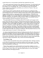
workplace.
Means of generation
10-25% RH
65-90% RH
Walking across carpet
35,000V
1,500V
Walking across vinyl
12,000V
250V
Worker at bench
6,000V
100V
Poly bag picked up from 20,000V
bench
1,200V
Chair with urethane
foam
1,500V
18,000V
Typical Voltage Levels
The chart shows you how much voltage is produced just through daily activities and how sensitive they are to humidity levels. It also brings to light how
high voltages can be generated at your electronics workbench! Many modern
components can’t handle a discharge of more that 1,000V. Older components
often can’t handle more than 10 volts! Of course static potential doesn’t indicate definite ion flow. When a potential like 35,000V is generated on your
body (by you walking around a room), sharp points all over your body leak the
ions into the air where they eventually get back to the carpet fibers you walked
across and pull the high charge from originally. As the ions leak off of your
body, the voltage becomes lower and lower until ion flow ceases.
IG7 Page 12
RAMSEY “LEARN-AS-YOU-BUILD” ASSEMBLY STRATEGY
Be sure to read through all of the steps, and check the boxes as you go to be
sure you didn't miss any important steps. Although you may be in a hurry to see
results, before you switch on the power check all wiring and components for
proper orientation. Also check the board for any possible solder shorts, and/or
cold solder joints. All of these mistakes could have detrimental effects on your
kit - not to mention your ego!
Kit building tips
Use a good soldering technique - let your soldering iron tip gently heat the
areas which you are soldering by heating both wires and pads simultaneously.
Apply the solder on the iron and the pad when the pad is hot enough to melt the
solder. The finished joint should look like a drop of water on paper, somewhat
soaked in.
Mount all electrical parts on the top side of the board provided. The top side
is clearly marked with the ‘Silk Screen’ reference designators. This is the side
that has no circuit traces on it. When parts are installed, the part is placed flat to
the board (unless otherwise instructed) and the leads are bent on the backside
of the board to prevent the part from falling out before soldering (1). The part is
then soldered securely to the board (2-4), and the remaining lead length is then
clipped off (5). Notice how the solder joint looks on close up, clean and smooth
with no holes or sharp points (6).
IG7 Page 13
Since this is a High Voltage product, we sincerely hope you put this together
in a professional manner. This project will not work as well as you wished if you
just slap it together without following good assembly techniques and all the
instructions. No matter how clear we may think our manual is, if you have any
questions, give us a call at the factory instead of jumping to conclusions. We
will be happy to help you with any problems.
This is a high voltage project so we want to mount the parts AS LOW AS
POSSIBLE to the board. A 1/4” lead length on a resistor not mounted close to
the board can act as a potential shorting point while experimenting. Be aware
though that there are stand up components in your circuit. They don’t need to
be squished to the board. Just follow the specific instructions and check them
off as you go.
For each part, our word "Install" always means these steps:
1. Pick the correct part value to start with.
2. Insert it into the correct PC board location, making sure the part is
mounted flush to the PC board unless otherwise noted.
3. Orient it correctly, follow the PC board drawing and the written directions
for all parts - especially when there's a right way and a wrong way to solder
it in. (Diode bands, electrolytic capacitor polarity, transistor shapes, dotted
or notched ends of IC's, and so forth.)
4. Solder all connections unless directed otherwise. Use enough heat and
solder flow for clean, shiny, completed connections.
Keeping this in mind, lets begin by sorting out our components and crosschecking them against the parts list to make sure we have received everything.
NOTE TO NEWCOMERS: If you are a first time kit builder you may find this
manual easier to understand than you may have expected. Each part in the kit
is checked off as you go and a detailed description of each one is given while
you install them. If you follow each step in the manual in order, and practice
good soldering and kit building skills, the kit is next to fail-safe. If a problem
does occur, the manual will lead you through step by step in the
troubleshooting guide until you find the problem and are able to correct it.
IG7 Page 14
RAMSEY IG7 PARTS LIST
Supplies
1 ...HVDC-1 7.5 kV Ion power supply
1 ...PC Board with 7 large holes
1 ...PC Board with 5 large holes
1 ...Base mounting PC board
4 ...L Brackets
7 ...#16 Nails, 1 1/4” long
4 ...Large rubber feet
1 ...small size LED (for HV indicator)
1 ...1K Ohm resistor (brown-black-red)
1 ...2.1 mm Power jack
7 ...1/2 Inch copper pipe couplers
2 ...#4 x 1/4” sheet metal screws
8 ...#4 x 3/16” machine screws
1 ...Neon light indicator
10” of #16 black stranded wire (for grounding)
IG7 Page 15
ASSEMBLY
Assembly of you Ion Cannon is pretty simple. It does however require a
pretty hot soldering iron and some patience. Most of this kit is mechanical in
nature so think of it more like an erector set.
1. We will begin by assembling the most difficult item first in order to get it
out of the way. This requires a bit of solder and a lot of patience to make it
look good. Please don’t rush this part. For this step you will need the
seven couplers and the board with the seven holes in it. The goal is to
solder all seven couplers so that they mount in place about 1/2 way
through the circuit board.
To make this job a bit easier, you may wish to make a temporary jig to
hold the PC board up in place. Use something heat resistant and about
half the height of the copper couplers in order to mount them at their midpoint in the holes. The setup should be secure enough that you can solder
to it easily.
2. Solder the center coupler first. You do not need to solder all the way
around the coupler unless you really want to. A full ring of solder is very
difficult to do since once the pipe gets hot enough, all of you solder will run
away on you. Soldering two opposite sides of each of the tubes in order to
make sure they stayed in place is fine. When you are done soldering this
coupler, blow on the pipe until it is cool! You don’t want to handle it when it
is hot enough to melt solder.
3. Using the same process, solder the remaining pipes in place. Try to
keep them level with the first pipe and centered just like the first one.
Once you get three pipes in a row installed, the rest will be easier to
position.
Tack Solder Example of the Pipe Installation
IG7 Page 16
4. Set aside the pipe and board assembly. We will now work on the nail (pin
elements) assembly.
5. First thing first we are going to sharpen these nails. There are plenty of
ways to sharpen nails but the easiest way is to use fine file to round and
sharpen the points. Remember the sharper the better! It can take a while to
get a good sharp point at the very tip so take your time. Note that nails are
typically not extremely hardened steel so you wont get a tip that could cut
an atom in two. It is however sharp enough for our purposes. How sharp is
sharp enough? You can test the end by poking your finger and if it hurts…
it’s sharp… Duh! The other way is to look at the end with a magnifying lens
so you can clearly see how well you have sharpened the tip. Probably the
preferable way!
6. The next step is to mount the seven nails being used as our electrode
elements. We want the nails to point straight out from the board as they will
be positioned with the points inside the ion tubes. Insert the nails from the
solder side of the PCB with the 5 large holes. It is labeled with Nail1 - Nail7
on the opposite side. You might want to scrape away a little more of the
green resist layer from around the nail holes to make them easier to solder
with the head flush to the copper side of the board.
Solder Example of the Nail Installation
7. Solder all seven nails into place. This does take some decent heat as
the nails have a zinc coating that makes it a bit difficult to solder to. Once
they are hot enough though, the solder will flow.
8. Set the nail assembly aside for now and let’s begin work on the main
board assembly. We will start with the small components and go up from
there.
9. Install R1, the 1K ohm resistor (brown-black-red). This resistor is used
to limit current through the front panel LED. ensuring that is runs at the
correct brightness. Hey, a little circuit theory always helps!
IG7 Page 17
10. Install D1, the LED. Note that this is one of the exceptions to the rule,
you want to leave the leads as long as possible! You want the LED to
stand up at least 3/4” off of the board when you solder it in place. We will
later bend over the leads so that the LED will poke its little head out of the
front panel pipe assembly board. Remember, LEDs are diodes, they will
only work if installed in the correct orientation! Notice that one lead is
longer than the other and that there is a small flat edge on one side of the
epoxy case. This indicates the Cathode. An indication of the flat side
orientation on the silk screen helps you line up the LED on the PC board.
11. Install J1, the 2.1 mm power jack.
12. Time to mount the Ion Generator (PS1) high voltage supply. You will
be mounting the Ion Generator on the top side of the board (the same
side as the silk screen). Make sure to orient it so that the wires are
pointing to the same side of the board that the power connector is on. Use
the two #4 self tapping sheet metal screws to affix it to the PC board.
13. Let’s begin wiring up the Ion Generator now. The silk screen on the
board has been labeled to show the function of the individual wires.
14. Solder the black wire into the hole marked GND PWR. To do this,
make sure the wire is stripped and tinned (if not done already) and placed
through the hole then soldered on the bottom side of the board.
15. Solder the thin white wire to the hole marked GND HV. This is the high
voltage return wire and it is the same thickness as the black wire.
16. Solder the red wire into the hole marked +12V. This is the power to
the Ion Generator.
17. You should have the thicker high voltage wire left to attach at this
point. We will solder this to the nail board later.
18. Using the four L brackets, the next step will be to mount the pipe
board and the nail board to the main PC board.
19. Using four of the #4 x 3/16” screws, mount the L brackets to pipe
board (front side) and the nail board (back side) in the bottom corners.
Note the copper side of the two boards should be facing the Ion Generator
module. These brackets will mate-up with the holes on the main board
and allow you to experiment with the positioning of the nail elements.
20. Use four #4 x 3/16” screws to mount the L brackets to the main board.
Use the two holes on the very end of the main board for one set (these
are the mounts for the pipe board marked M3 and M4). Use the other two
in the two holes marked M1 and M2. These are the standard board
positions.
IG7 Page 18
Attaching the Boards To the Main Board
21. Now solder the final larger white wire of the Ion Generator to the bare
pad provided on the back side of the nail board in the upper right corner.
22. Check nail positions within the copper tubes and make sure they are
approximately centered. They don’t have to be right in the middle but if
they are cocked at an angle, you may wish to heat up the solder and reposition the nail to center it properly.
We’re done with the assembly of your Ion Cannon! Now is probably a good
time to re-read the safety precautions before you plug it in.
The Finished Product!
IG7 Page 19
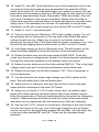
Parts Layout
MAIN BOARD
NAIL BOARD
PIPE BOARD
IG7 Page 20
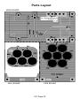
IG7 Page 21
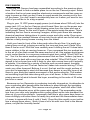
EXPERIMENTS
On a personal note; back when I was in Junior High School, I really wished
kits like this were available. I always loved tinkering with high voltage and seeing the strange phenomenon associated with high voltage and high power.
Maybe this was a fixation with fire... or maybe something else (Froyd could
better answer than I can). I used to have to dig around in old television sets
looking for flyback transformers and high voltage diodes, praying that when I
found one, it wasn’t the reason why the TV was by the curb. I don’t even want
to mention how much I had to pay out of pocket for high voltage diodes and
capacitors! Now I have gathered all of the pieces together in a reputable kit
that actually has a warranty, imagine that! Life is so easy now.
I actually found this little gem of a high voltage power supply while working
on another high voltage kit, the PG13. A nice company in Taiwan specializes
in high voltage power supplies and they sent this item along for us to play
with. Oh boy this is a neat little supply, much better than those $4.00 versions
you see in some electronics surplus catalogs! Here is a quick message they
sent me about the difference:
“* There is other ion generator in the market similar to ours and the unit
price is approx. USD3.- , it is AC110V, pulse type, the output power is less
than 1/6 of ours, the output voltage will vary with discharge devices and the
output voltage is un-adjustable also can not meet EMI regulation.”
(Pardon their English, you should see my Taiwanese! They’re doing well!!)
Thus why ours is a bit more expensive. In fact when I was initially playing
with the power supply I was quite impressed by how well is worked, the consistent corona it produced, and how easy it is to use. It was originally designed
for car air filter use hence the reason why it runs on +12V. Because of this
however, you can isolate the power supplies from one another and so some
pretty interesting stuff. I will leave that up to you to play with.
Our first experiment of course is the kit we just put together, the Ion Cannon.
The idea of the ion cannon is to be able to disperse ions into the air efficiently
and with relatively low voltages (less than 10 kV). This little project shows
many properties of ions that will help you understand how they work and show
many neat scientific principles of ions, ion wind and more.
IG7 Page 22
ION CANNON
Once the Ion Cannon has been assembled according to the previous directions. We’ll need to find a suitable place to run the Ion Cannon project. Select
a location that is not near sensitive electronics components and has easy access to power so that you don’t have to reach across the running unit to turn
off the power. You don’t want to accidentally lean on it when you want to turn
it off or you will be in for a big surprise!
Plug in your 12 VDC power supply power (unit draws about 350 mA) into the
power jack (J1) on the Ion Cannon circuit board. Now turn on the power supply. You may possibly hear a slight hissing noise from the tubes and see a
small purple “flame” on the end of each of the points inside the pipes. This is
indicating that ion flow is occurring! Imagine, at this point there are complex
chemical reactions taking place to create ozone and nitric oxide. Even more
important is the constant release of ions into the air which can be felt with your
hand as a fairly strong breeze coming from the tubes!
Hold your hand in front of the tubes and notice the air flow. It is pretty surprising how much air is being moved by the ions and how cool it feels. Why
does it feel so cool? Well the ions certainly aren’t chilling the air! It does have
some relation to the air moving however. If you compared this ion-pushed air
to the air of a fan that moved the same amount of air, this system would seem
much cooler thanks to a common meteorological term called “Wind Chill Factor”. Yes it is the same weather phenomenon that we New Yorkers (up here in
Victor) have to deal with every time we step outside! “Wind Chill Factor” is designed to let us know how cold it feels to your skin versus how cold it actually
is outside. It is related to a variety of factors such as wind speed, humidity,
and how hairy you are! The hair factor isn’t taken into account during TV forecasts very often however! Believe it or not, the hair and the rough surface of
your skin is important in wind chill because they keeps a very thin layer of air
close to your body that resists movement of the surrounding air. This makes
an insulating layer that rides along with you at all times. In fact it takes a surprising amount of wind to break this layer, something in the order of 20 miles
per hour or more!
Because our Ion Generator is producing ionically charged air, its attraction to
your conductive skin barrels allow the breeze to pass through the insulating
layer with very little effort. This causes a much greater ‘wind chill effect’ than
what would otherwise occur at the same wind speed. The evaporating moisture from your skin only heightens this cooling effect as the ions transport the
drier air to your skins surface. I personally feel this is why some days seem so
bone-chillingly cold when there is hardly any wind and the thermometer doesn’t seem to agree with how it cold it ‘feels’. Days like this usually occur just before a strong snow storm. I think it has a lot to do with ionic flow in the atmosphere, not just the humidity levels!
IG7 Page 23
Lets try some fun stuff now. Take the small neon light included with your kit
and hold on to one of the leads. Point the other lead towards the tubes in the
path of the discharged air. DO NOT STICK THE LEAD INTO THE TUBES! If
you look closely, you should be able to see the neon light periodically flashing.
This indicates that the air coming out of the pipes retains at least 60 volts of
charge which is going through the bulb and in to you! You don’t feel this because the current is very small. You may need to turn of the lights in the room
to see the flashes.
Look at the additional holes on the front end of the main board. These will
allow you to adjust the distance of the high voltage tips (the nails) from the
end of the pipes (the ion tube array) giving you to the ability to adjust the
quantity of air to ions ratio. The more air that is moved, the less energy the
ions will have when they escape the ends of the tubes, if they can even escape at all. Can you guess which way the needles have to be moved to generate more air flow and fewer ions?
Using the 10 inch long piece of wire, solder it between one end of the neon
bulb and a ground point on the bottom of the main board. The solder mask resist layer has been removed in the area of the screw mounts and provide a
convenient contact point for this purpose. Safety-wise, soldering the wire
firmly into place is best versus just wrapping the wire around one of the
mounting screws (less likely hood it will fall off!).
Try using the neon bulb method like before but this time use a stop watch
and try to count the number of flashes you can see in a minute. Position the
sensing end of the neon bulbs’ lead wire about 1/2” away from the end of the
pipes and start counting. Record your results for further comparison.
Now move the nails closer to the ends of the tubes by moving the nail board
forward. Repeat the same measurements again and record you count value.
Work your way through all of the mounting positions recording your results as
you go. Notice any pattern?
If the experiment went well, you should have seen that the closer the nails
are positioned to the end of the pipes, the faster the neon bulb would blink.
The neon bulb is actually giving you an indication of current, or the amount of
free ions in the air. Here’s how it works. The lead of the neon bulb that is
pointing into the airflow attracts the released ions. The terminals inside the
bulb act like a very small capacitor and allow a charge to build up inside the
bulb. When the built up charge reaches about 60 volts, the neon gas ionizes
and the bulb lights up. At this point, the current flow begins discharging the
small ‘capacitor’ and causes the terminal voltage to drop below around 40
volts. At this voltage, ionization of the neon gas stops and the light goes out.
If the ‘collected’ ions have low a potential, the neon bulb will not be able to
reach 60 volts break down voltage and it will never flash over. This does not
IG7 Page 24
mean there are no ions present, just that their potential is too low.
The next experiment requires some objective observing. You will need to put
your Ion Cannon in a place that normally contains a lot of bad smells like in
the garage over the garbage can, or in the bathroom near the porcelain
throne. Note the smell before and after you run the Ion Cannon. Can you
guess what is going on?
Now that you have worked with the unit a bit, have you noticed a pretty
strong “electronic” smell coming from the Ion Cannon tubes? Most of what you
are smelling is Ozone. Ozone is a fairly reactive gas and in high quantities can
trigger asthma attacks or aggravate other heath problems. Thankfully, the
quantity coming out of our Ion Generator is pretty safe as long as you have a
little air circulation. You wouldn’t want to stuff yourself in a cardboard box with
the IG7 running and breath it in all day however. Not to be morbid, but you
would probably suffocate long before Ozone got you.
The generated Ozone is a oxidizer (after all it is made up of oxygen molecules) much like that of Chlorine. Chlorine has long been used in homes and
businesses as a cleaning agent because it is very good at disinfecting and deodorizing. Since most smells are organic in nature, they can be very reactive
as well. A molecule of smelly gas that comes into contact with an oxidizer in
the air can cause a reaction. The results of which is a mixture of gasses that
will more likely be ‘non smelly’, like carbon dioxide and water. Some gasses
like sulfur dioxide won’t be effected but most of the obnoxious ones will. That
is what makes the little Ion Cannon so effective. Not only does it move air, but
it also emits ozone to ‘scrub it’ at the same time.
In cases of particles like dust that are floating around in the air, they are usually neutral charged. As the Ion Cannon spits out negative ions, they are attracted to and cling to these floating particles. Once the particles are charged
by the ions, they become attracted to neutral items like the walls and ceiling.
Commercial ‘air purifiers’ often work in this manner by using a grounded filter
element to collect the particles. Hey, that’s how those things work!
The Rubber Test
Here is a neat idea that the boss came up with back when I left this running
in my office (he wanted to see just how reactive the Ozone was). This also
shows how sensitive rubber is to Ozone and why natural rubber doesn’t last
very long exposed to moving air.
Take a few regular brown rubber bands and wrap them tightly around a
small box. Place the box in the air flow coming from the Ion Cannon and let it
run for a day or two. Have you seen this effect before on a few old rubber
bands that were left laying around?
IG7 Page 25
Pinwheel (Corona Motor)
The Pinwheel experiment is the old standby experiment that demonstrates
ionic flow as well as Newton’s 3rd law of Motion: “For every action there is an
equal and opposite reaction”. When we expend ions off into the air with our
Ion Cannon, we are not only pushing air out of the ends of the pipes, but we
are also pushing the Ion Cannon in the opposite direction. Granted this force
is pretty small in our case, but the pinwheel experiment helps to demonstrate
the basic principle very well.
Copy the template (or cut it out) of the metal pinwheel and use it to cut a
piece of tin to form. Using this “rotor” will demonstrate how the ions that are
being released from the sharp tips also push back with equal force. The force
exerted back on the tips will make the rotor spin in the opposite direction of
the ion stream!.
1. Be sure to use leather gloves or even butchers’ gloves to prevent slicing up your hand from the sharp metal edges when cutting our your rotor.
Blood drops can through your rotor system off balance!
2. Cut the top and bottom off of a soda can, and slice it down one side.
3. Bend out and form the aluminum so that it is flat.
4. Cut out the pinwheel diagram from the manual so you can use it as a
template to later cut the tin in a desired shape. Tape it on to the flat aluminum sheet.
5. Tap a nail on the center point light enough that it doesn’t go through the
metal. It should just leave a dimple that we can use to balance the rotor on
a support nail. This will form our “frictionless” bearing!
6. Using sharp scissors to cut out the template. Make sure to use bold single slices with the scissors. Not a bunch of little slices that will leave many
sharp points and make the rotor ineffective. You can always go back and
trim off the sharp edges later.
7. Verify that the Ion Cannon is powered down and unplugged.
8. Unsolder the high voltage lead of your Ion Cannon from the nail board.
9. Using an insulated post like a hunk of plastic or small plastic soda bottle, hammer a nail through the lid so that it points out the top.
10. Secure the high voltage lead to the nail, make sure the nail base is
stable.
11. Balance the rotor on top of the nail. Use small pieces of tape as
weights to balance your rotor if needed so that it stays level by itself.
IG7 Page 26
12. Power up the Ion Generator, and watch the motion of the rotor!
This demonstrates how ions can be used for propulsion! In fact NASA has
employed this process on some space crafts to help them maneuver in outer
space. Ion propulsion is used to slowly reposition the craft, and also assist in
acceleration. There isn’t much gas in space to ionize, but there is apparently
enough for this to work!
Pinwheel Template
DANGER
HIGH VOLTAGE
See instruction manual before operation
IG7 Page 27
This page has been left blank so you may cut the pinwheel
template out of the manual without losing any juicy information!!
IG7 Page 28
TROUBLESHOOTING
PROBLEM: The LED doesn’t light up.
SOLUTION: Not much that can go wrong in this circuit. Double check your solder connections again. It is quite possible you have a dead short someplace
so you had better check it out without the power applied! This is most likely
caused by the diode orientation. Check the Flat side against the silk screen.
PROBLEM: The LED lights, but no high voltage.
SOLUTION: There is probably an assembly problem. The main HV power
supply included in this kit is very rugged, so it is very unlikely that it was
accidentally damaged during assembly. You will definitely want to check your
wiring that interfaces with the circuit board.
PROBLEM: The unit ran fine for weeks but now it seems to have lost its poop!
SOLUTION: You may need to clean the nail points and the inner lining of the
ion tubes. Dust and other deposits can build up after a while and reduce the
ion generating capability of the system.
IG7 Page 29
CONCLUSION
We sincerely hope that you enjoy the use of this Ramsey product. As always,
we have tried to compose our manual in the easiest, most user-friendly format
that is possible. As our customers, we value your opinions, comments, and
additions that you would like to see in future publications. Please submit
comments or ideas to:
Ramsey Electronics Inc.
Attn. Hobby Kit Department
590 Fishers Station Drive
Victor, NY 14564
Please feel free to visit our Website at www.ramseyelectronics.com and offer
your observations to other kit enthusiasts as well.
And once again, thanks from the folks at Ramsey!
IG7 Page 30
The Ramsey Kit Warranty
Please read carefully BEFORE calling or writing in about your kit. Most problems
can be solved without contacting the factory.
Notice that this is not a "fine print" warranty. We want you to understand your rights and ours too! All
Ramsey kits will work if assembled properly. The very fact that your kit includes this new manual is your
assurance that a team of knowledgeable people have field-tested several "copies" of this kit straight from
the Ramsey Inventory. If you need help, please read through your manual carefully. All information
required to properly build and test your kit is contained within the pages!
1. DEFECTIVE PARTS: It's always easy to blame a part for a problem in your kit, Before you conclude
that a part may be bad, thoroughly check your work. Today's semiconductors and passive components
have reached incredibly high reliability levels, and it’s sad to say that our human construction skills have
not! But on rare occasions a sour component can slip through. All our kit parts carry the Ramsey
Electronics Warranty that they are free from defects for a full ninety (90) days from the date of purchase.
Defective parts will be replaced promptly at our expense. If you suspect any part to be defective, please
mail it to our factory for testing and replacement. Please send only the defective part(s), not the entire kit.
The part(s) MUST be returned to us in suitable condition for testing. Please be aware that testing can
usually determine if the part was truly defective or damaged by assembly or usage. Don't be afraid of
telling us that you 'blew-it', we're all human and in most cases, replacement parts are very reasonably
priced.
2. MISSING PARTS: Before assuming a part value is incorrect, check the parts listing carefully to see if it
is a critical value such as a specific coil or IC, or whether a RANGE of values is suitable (such as "100 to
500 uF"). Often times, common sense will solve a mysterious missing part problem. If you're missing five
10K ohm resistors and received five extra 1K resistors, you can pretty much be assured that the '1K ohm'
resistors are actually the 'missing' 10 K parts ("Hum-m-m, I guess the 'red' band really does look orange!")
Ramsey Electronics project kits are packed with pride in the USA. If you believe we packed an incorrect
part or omitted a part clearly indicated in your assembly manual as supplied with the basic kit by Ramsey,
please write or call us with information on the part you need and proof of kit purchase.
3. FACTORY REPAIR OF ASSEMBLED KITS:
To qualify for Ramsey Electronics factory repair, kits MUST:
1. NOT be assembled with acid core solder or flux.
2. NOT be modified in any manner.
3. BE returned in fully-assembled form, not partially assembled.
4. BE accompanied by the proper repair fee. No repair will be undertaken until we have received the
MINIMUM repair fee (1/2 hour labor) of $25.00, or authorization to charge it to your credit card account.
5. INCLUDE a description of the problem and legible return address. DO NOT send a separate letter;
include all correspondence with the unit. Please do not include your own hardware such as non-Ramsey
cabinets, knobs, cables, external battery packs and the like. Ramsey Electronics, Inc., reserves the right
to refuse repair on ANY item in which we find excessive problems or damage due to construction
methods. To assist customers in such situations, Ramsey Electronics, Inc., reserves the right to solve their
needs on a case-by-case basis.
The repair is $50.00 per hour, regardless of the cost of the kit. Please understand that our technicians are
not volunteers and that set-up, testing, diagnosis, repair and repacking and paperwork can take nearly an
hour of paid employee time on even a simple kit. Of course, if we find that a part was defective in
manufacture, there will be no charge to repair your kit (But please realize that our technicians know the
difference between a defective part and parts burned out or damaged through improper use or assembly).
4. REFUNDS: You are given ten (10) days to examine our products. If you are not satisfied, you may
return your unassembled kit with all the parts and instructions and proof of purchase to the factory for a full
refund. The return package should be packed securely. Insurance is recommended. Please do not cause
needless delays, read all information carefully.
IG7 Page 31
IG7 ION CANNON KIT
Quick Reference Page Guide
Safety Guidelines .................................4
Ion Theory .............................................6
Parts List .............................................15
Assembly .............................................16
Parts Layout ........................................20
Schematic ............................................21
Experiments ........................................22
Troubleshooting...................................29
Warranty ..............................................31
REQUIRED TOOLS
• Soldering Iron Ramsey WLC100
• Thin Rosin Core Solder Ramsey RTS12
• Needle Nose Pliers Ramsey MPP4 or RTS05
• Small Diagonal Cutters Ramsey RTS04
<OR> Technician’s Tool Kit TK405
ADDITIONAL SUGGESTED ITEMS
•
•
•
Holder for PC Board/Parts Ramsey HH3
Desoldering Braid Ramsey RTS08
Digital Multimeter Ramsey M133
Price: $5.00
Ramsey Publication No. MIG7
Assembly and Instruction manual for:
TOTAL SOLDER POINTS
22
RAMSEY MODEL NO. IG7
ESTIMATED ASSEMBLY
TIME
Beginner .............. 1 hrs
Intermediate ........ 0.5 hrs
Advanced ............. 0.5 hrs
RAMSEY ELECTRONICS, INC.
590 Fishers Station Drive
Victor, New York 14564
Phone (585) 924-4560
IG7 Page 32
Fax (585) 924-4555
www.ramseykits.com
DANGER
HIGH VOLTAGE
See instruction manual before operation