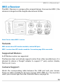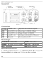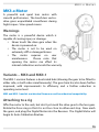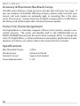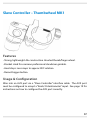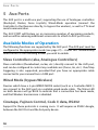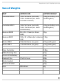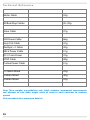
1
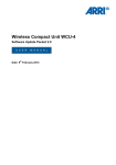
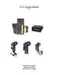
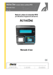
RTMOTION MK3.x
Lens Control System
User Guide
REVISION: 2013-09-05
www.rtmotion.com/support
MK3.x Lens Control System
1 MK3.x Lens Control System
Table of Contents
1. MK3.x Lens Control System.........................................................................2
2. Quick Start Guide .........................................................................................3
Initial Setup............................................................................................................................ 3
Camera Run/Stop................................................................................................................. 3
3. System Overview..........................................................................................4
Introduction........................................................................................................................... 4
Theory of Operation............................................................................................................ 4
Wireless.................................................................................................................................... 5
Accessories............................................................................................................................. 5
Usage Chart........................................................................................................................... 6
4. Components..................................................................................................7
MK3.x Controller .................................................................................................................. 8
MK3.x Receiver................................................................................................................... 13
MK3.x Motor........................................................................................................................ 15
Slave Controller – Thumbwheel MK1.........................................................................17
5. Aux Ports.....................................................................................................18
Available Modes of Operation ..................................................................................... 18
Setting the AUX PORT's Mode...................................................................................... 19
6. Updating Firmwares...................................................................................20
7. Menu Tree....................................................................................................26
8. Technical Reference....................................................................................29
Compatibility Guidance.................................................................................................. 29
Pin-Outs................................................................................................................................ 30
Sizes & Weights................................................................................................................... 33
9. Troubleshooting.........................................................................................35
10. Additional Information............................................................................37
Usage & Environment...................................................................................................... 37
12/24 Month WARRANTY................................................................................................ 37
Contact Information......................................................................................................... 37
2
Quick Start Guide
2 Quick Start Guide
Initial Setup
1
Plug 12V into the RECEIVER's “PWR” port.
Max voltage is 17V. If the voltage is over ~17.5V or polarity is reversed,
The Receiver will block the dangerous voltage and not start.
2
Affix one or more MOTORS to the rods/ lens.
Note that the motors are labelled as FOCUS, IRIS, etc.
3
Plug the motors into the RECEIVER unit.
The motor port that the motors attach to isn't important. The motors will begin
calibrating.
4
Put a Canon LP-E6 battery in the Hand Unit and hold down
the PWR button.
Camera Run/Stop
1
Connect the appropriate Run/Stop cable from the CAM
port on the Receiver to your Camera.
2
Enter the Controller’s MENU, Select CAMERA, then select
which camera you have connected.
3
You can now Run/Stop the camera with the REC button.
3
System Overview
3 System Overview
Introduction
The RTMOTION MK3 Lens Control system is optimised for high-end Wireless
and Wired remote control of Cinema and Still camera lenses.
The range is specifically designed to enable a low-cost entry point (single
motor), with a broad expansion capability.
A large number of accessories are in development to further expand on the
range's capability (gimbal controllers, underwater controllers, etc.), and we
always welcome feedback on how we can better serve your needs.
Theory of Operation
Smart Motors
The MK3 MOTOR units are intelligent smart motors, with built-in electronics
which handle all seeking and calibration behaviour. When powered up, the
motor will find the lens end-stops and learn the characteristics of the attached
lens. It does all of this without any help from the Receiver or Controller.
Each motor remembers its CLASS (focus, iris, zoom), and its RESPONSE
(normal, fast, slow). You can therefore plug any motor into any Receiver port.
To re-configure a motor, you need to use the CONTROLLER menus.
Since the motors have their own intelligence, they need only a small 4-pin
lemo cable for operation.
4
System Overview
Receiver Unit
Offloading some electronics into the smart motors has enabled us to
dramatically shrink the Receiver in size. It handles only NETWORKING and
CAMERA INTERFACE operations. This has enabled a system with low cost,
high flexibility and very small size.
Controller (Hand Unit)
The Controller is the main brain of the unit. Via its OLED screen it also handles
the remote-configuration of the Receiver and Motor.
Wireless
RF3 Generation
From MK3.1 onwards, devices include our latest RF3-Generation wireless
modules. We strive to stay at the forefront of performance, and therefore we
have jumped at the opportunity to offer what we believe is the longest range,
most interference-immune wireless solution on the market. FCC and CE
certification is of course retained, and we are now right up to the legal limit.
Accessories
Slave Controllers
Slave Controllers are simple (affordable) devices—such as joysticks,
thumbwheels, record buttons—which rely on external electronics to function.
To use a Slave Controller, you need to attach it to an RTMOTION device with an
AUX socket. For example, RECEIVER MK3.1.
Smart Controllers
Smart Controllers contain electronics, and therefore do not require a
Controller or Receiver. You need only POWER and a MOTOR. Our range of
smart controllers are estimated for shipping in late 2013.
5
System Overview
Usage Chart
6
Components
4 Components
Table of Contents
MK3.x Controller .................................................................................................................. 8
MK3.x Receiver................................................................................................................... 13
MK3.x Motor........................................................................................................................ 15
Slave Controller – Thumbwheel MK1.........................................................................17
7
MK3.x Controller
MK3.x Controller
The MK3.x CONTROLLER gives from 3 to 6 axis control.
Note: Picture shows MK31/Z variant with optional Force Zoom Joystick.
Configurations
Any INPUT (Large knob, Side Knob A, etc.) can be assigned to any LENS AXIS.
For example, an MK3/B “Basic” controller can be configured so that the MAIN
KNOB controls Focus, SIDE KNOB A controls Iris, and SIDE KNOB B controls
Convergence.
All variants are capable of simultaneously controlling at least 3 axis, so are
effectively “FIZ” and “3D” capable.
8
MK3.x Controller
There are however significant ergonomic advantages to industry standard
controls, so for fine control it is recommended that the Force Joystick is used
for Zoom, and the Slider is used for IRIS.
MK3 Variants
MK3 versions have RF2 wireless modules. See section page 29.
1
MK3/B, “Basic”. 3 Axis Control
Large Focus Knob, 2x Side Knobs (A and B).
2
MK3/S, “Stereo”. 4 AXIS CONTROL
Large Focus Knob, Slider, 2x Side Knobs (A and B).
3
MK3/Z, “FIZ”. 6 AXIS CONTROL
Large Focus Knob, Slider, Force Joystick (X/Y), 2x Side Knobs (A and B).
MK3.1 Variants
MK3.1 versions have RF3 wireless modules. See section page 29.
1
MK31/S, “Stereo”. 4 AXIS CONTROL
Large Focus Knob, Slider, 2x Side Knobs (A and B).
2
MK31/Z, “FIZ”. 6 AXIS CONTROL
Large Focus Knob, Slider, Force Joystick (X/Y), 2x Side Knobs (A and B).
9
MK3.x Controller
Operation
1
Power On
Hold down the POWER button for 2 seconds to turn the unit ON / OFF.
2
Camera Run/ Stop
Press the REC button to start recording. Press REC again to stop recording.
Note: you must use the correct Run/Stop cable for your camera and select the correct
option in MENU / CAMERA.
3
Status LED
OFF – Unit is OFF
ORANGE – No Connection GREEN – Unit is Connected
BLUE – Wired Mode RED – Camera Running
4
PURPLE – Please Wait
PC Mode / Bootloader
Turn off the Controller. Hold down the SET button. Keep SET held, and also
hold down the POWER button. The Status LED will go Orange, and the screen
display: “PC MODE”. You can now connect the controller to a PC and it will
show as a USB device.
5
Battery / Power
The Controller takes a CANON TYPE LP-E6 BATTERY, as used in the Canon 5D,
7D, etc.
It can also run from the MICRO USB connector (5V). Please note, minimum is
approx 4.65V- some laptops, etc. don't provide quite enough voltage.
6
Factory Reset
Enter the MENU / ADVANCED / FAC RESET.
Short-cut: You can also hold POWER and press MENU.
10
MK3.x Controller
CONTROLLER MENU
Press the MENU button to enter the menu.
You can then navigate with the UP, DOWN and SET buttons.
To go back one step, press MENU.
To abort and pull out of the menu, press POWER.
For a full breakdown of menu functions, go to page 27.
Default Configurations
MK3/B “BASIC” MK3/S “STEREO”
MK3/Z “FIZ”
Large Knob
→
FOCUS
FOCUS
FOCUS
Slider
→
(not present)
IRIS
IRIS
Force Joystick Y →
(not present)
(not present)
ZOOM
Force Joystick X →
(not present)
(not present)
(Inactive)
Side Knob A
→
IRIS
ZOOM
ZOOM SPEED
Side Knob B
→
ZOOM
INTER-OCULAR
INTER-OCULAR
11
MK3.x Controller
Low Battery Indication
The Controller will give a warning and automatically shut down when the
battery voltage falls to approx 6.1V. This is to protect the Battery from being
over-drained and reducing its life.
If your battery is fully drained and you wish to continue on USB power, you
must remove the LP-E6 battery from the unit.
Power Requirements
Canon LP-E6 battery:
6.2V to 8.4V.
USB Socket:
Approx 4.75V to 9V max.
12
MK3.x Receiver
MK3.x Receiver
The MK3.1 Receiver is a unique, ultra-compact design. From version MK3.1, the
antenna is integral and the length reduced even further.
Note: Picture shows MK3.1 version.
Variants
MK3 versions have RF2 wireless modules, and no AUX port.
MK3.1 versions have RF3 wireless modules. See section page 29 for more info.
Supported Motors
3x RT Motion motors are supported.
The Receiver does not natively support motors from other manufacturers. It is
planned to release a “dongle” adapter to support 3 rd party motors (Heden,
Preston, etc.) soon.
Camera Support
Attach the corresponding cable between the CAM port and your camera.
There are cables available for all major cameras (EPIC, ARRI, etc.). You must also
select your camera-type from the Controller Menu, see page 26.
13
MK3.x Receiver
Operation
Connection
MOTORS
Lemo 0B 4-pin
Any motor can connect to any port.
PWR
Hirose HR10 4-pin
Power Input, 1=GND, 4= Voltage.
CAM
Hirose HR10 4-pin
Trigger (Output) for CAMERA.
AUX
Lemo 0B 5-pin
Analogue controllers, Wired Mode, etc.
USB
Micro USB
For connection to a PC.
Status Light
SOLID GREEN – CONNECTED
PURPLE – Please Wait
ORANGE – No Connection (or PC Mode)
RED (solid) – Cam running
BLUE – Wired Mode
RED (pulse) – Cam trig
Power Requirements
5 – 14V DC (17V absolute max - e.g. 13.8V battery fresh off a charger). The
Receiver will block any voltage over ~17.5V, or any reverse voltage.
14
MK3.x Motor
MK3.x Motor
A powerful and quiet lens motor with
smooth performance. The brush-less vectordrive gives unparalleled smoothness during
high-torque / slow-speed moves.
Warnings
The motor is a powerful device which is
capable of causing injury or damage.
• Never touch the drive gear when the
device is powered on.
• The motor is not to be used on
extremely stiff or damaged lenses.
• The motor requires no user
maintenance.
Please note that
opening the motor can affect its
internal calibration and voids the warranty.
Variants – MK3 and MK3.1
The MK3.1 revision features a dual-sided hub (allowing the gear to be fitted to
either side, or both sides simultaneously). The gear train has also been further
improved, with improvements to efficiency and a further reduction in
operating noise level.
MK3 and MK3.1 models use identical firmwares and have identical compatibility.
Attaching to a rig
Affix the motor to the rods, but don't yet mesh the drive gear to the lens gear.
Rotate the focus ring so that it is not too close to either end stop. Now mesh
the gears, and plug the Digital Motor into the Receiver. The Digital Motor will
begin its Auto-Calibration Routine.
15
MK3.x Motor
Accuracy & Electronic Backlash Comp
The MK3 motor features a high-precision encoder that will never lose steps. If
you see evidence of backlash affecting accuracy, please make sure that your
mount, rails and camera are extremely rigid, as mounting flex is the main
cause of inaccuracy. Unique electronic backlash compensation is calibrated at
the factory and will be tweak-able via future firmware update.
Focus/ Iris/ Zoom Assignment
The Digital Motor is internally assigned a “Motor Class”, which is saved to nonvolatile memory. The motor will identify itself to the CONTROLLER via its
SERIAL NUMBER (lasered onto the motor back, example: 0500). To change the
class of a Digital Motor, or other performance parameters (performance mode,
direction of rotation, etc.) please refer to the manual for the Controller.
Specifications
Max Allowable Torque
Standard Gear
Nominal Current
Power Requirements
16
2.2Nm
0.8 mod, 50 Teeth
Approx 0.6A loaded
5-17V
Slave Controller – Thumbwheel MK1
Features
- Strong, lightweight Alu construction. Knurled thumb/finger wheel.
- Bracket sized for common professional steadicam gimbals.
- Hard stops. Lens maps to approx 200º rotation
- Record trigger button.
Usage & Configuration
Wire into an AUX port via a “Slave Controller” interface cable. The AUX port
must be configured to accept a “Knob/ Potentiometer” input. See page 19 for
instructions on how to configure the AUX port correctly.
17
Aux Por ts
5 Aux Ports
The AUX port is a multi-use port, supporting the use of Analogue controllers
(Knob/pot, Rocker, Force Joystick), Wired-Mode operation (connect the
Controller to the Receiver directly, to bypass the wireless), as well as TTL-level
serial communication.
The AUX PORT will feature on an increasing number of upcoming products,
and we will be releasing additional accessories to attach to AUX ports soon.
Available Modes of Operation
The following functions are supported by the AUX port. The AUX port must be
configured in the appropriate mode (see page 27) – it does NOT automatically
detect which of the following modes you wish to enable.
Slave Controllers (aka, Analogue Controllers)
Slave controllers (thumbwheel, rocker, etc.) directly connect to the AUX port,
and can be configured to control any available axis (Focus, Iris, etc.). Run/Stop
triggering is also supported, provided that you have an appropriate cable
connected to your camera from a CAM port.
Wired Mode (bypass Wireless)
Devices which have a 5-pin WIRED MODE socket (such as a Controller MK3.1)
can connect to the AUX port via a suitable wired-mode cable. The Status LED
on both devices will go BLUE to indicate that a connection has been made,
and that Wireless transmission is disabled.
Cinetape, Fujinon Control, Cook I/ data, RS232
Support for these protocols is coming soon. It will require an RS232 dongle,
between the AUX Port and the 3rd-party device.
18
Aux Por ts
Setting the AUX PORT's Mode
The AUX port must be in the correct mode. The setting is remembered after
power-cycling.
To configure the AUX PORT, use the CONTROLLER. Enter the MENU, then
select AUX.
Configure the auxiliary port on the RECEIVER. Note, if your Receiver
does not have an 5 pin AUX port, you will not have this menu.
AUX
MODE
What function to assign to the AUX PORT?
OFF
Disable the AUX port
WIRED
Configure AUX port for WIRED MODE (i.e. wire from Controller ->
Receiver to bypass radio)
KNOB
You have a KNOB or THUMBWHEEL attached to the AUX PORT.
ROCKER
You have a ROCKER attached to the AUX PORT.
FORCE
You have a FORCE SENSOR attached to the AUX PORT.
AXIS
Which axis to control with the attached AUX input device? N.B. This
does not apply if you are in WIRED MODE.
FOCUS
IRIS
(etc.)
MODE B
As “Mode” above, but for input axis B (for use with splitter)
AXIS B
As “Axis” above, but for input axis B (for use with splitter)
19
Updating Firmwares
6 Updating Firmwares
Introduction
This guide will take you step by step through the process of updating the
firmware on the Controller, Receiver and Motors. Updating the device
firmware is a normal process to take advantage of new features, bug fixes, and
general usability improvements based on feedback.
Cautions
Although the firmware updating process usually goes smoothly, very
occasionally users may need additional support. For that reason, we do not
recommend performing an update immediately before a shoot, in case of any
problems. See page 24 for firmware update troubleshooting.
Requirements
Currently, you require a PC running Windows XP or newer. A Mac OSX version
of the software is imminent.
Download the Latest Firmwares
Visit: www.rtmotion.com/page/support
Download and install the latest version for your platform. The package
includes the Firmware Updater application itself, plus the latest Device
Firmwares.
Follow @rtmotion on Twitter to be alerted to new features and important updates.
20
Updating Firmwares
Updating The Controller Firmware
1. Run the Program.
2. Make sure the controller is turned off.
3. Connect the USB cable from the Controller to your computer.
4. Hold down the SET and POWER buttons simultaneously on the
controller for about 2 seconds. The screen will display: PC MODE.
5. The program will now detect and connect to the Controller. You
should see, “Connected to Device” in the program.
6. In the “Firmware” section, use the drop down menu to select a
firmware version that matches your controller type:1. Select Controller_MK3-B... for the Basic Controller.
2. Select Controller_MK3-S... for the Slider Controller.
3. Select Controller_MK3-Z... for the Force-Zoom Controller.
7. Click the “Update Device” button.
Note: The first time you connect your device, your operating system may install HID
“Human interface device” drivers and require you to restart your computer. This is
normal.
21
Updating Firmwares
Updating The Receiver
1. Run the Program.
2. Make sure the receiver is not powered and that no motors are
attached.
3. Connect the USB cable from the Receiver to your computer. The
Receiver should power up.
4. The program will now detect and connect to the Receiver. You
should see, “Connected to Device” in the program.
5. In the “Which Device to Update” section, select Receiver from the
drop down menu.
6. In the “Firmware” section there should only be one firmware to
select from the drop down.
7. Click the “Update Device” button.
Note: If you connect the Receiver to a computer without having the Firmware Updater
Application already running, the Receiver will boot into “normal” operation and not be
visible as a USB device. Always run the Firmware Updater application BEFORE attaching
the Receiver to the computer.
Note: The first time you connect your device, your operating system may install HID
“Human interface device” drivers and require you to restart your computer. This is
normal.
22
Updating Firmwares
Updating a Motor
1. Run the Program.
2. Make sure the Receiver is not powered and that no motors are
attached.
3. Connect the USB cable from the Receiver to your computer.
The Receiver should power up.
4. The program will now detect and connect to the Receiver. You
should see, “Connected to Device” in the program.
5. Attach 12V power to the Receiver.
6. In the “Which Device to Update” section, select Motor from the
drop down menu.
7. In the “Firmware” section there should only be one firmware to
select from the drop down.
8. Click the “Update Device” button.
9. Attach ONE motor to the Receiver. The update process should
begin.
10. When the motor begins moving, detach it from the Receiver.
The process is complete.
11. If you need to update another motor, go to step 8.
Note: You can only update one motor at a time. Do not attach more than one motor or
the update will fail.
23
Updating Firmwares
Firmware Updating Troubleshooting
I get an “This application has failed to start because...” error.
You may need to install the Microsoft Visual C++ 2010 Redistributable
Package.
The installer should install this if it’s not installed but they can also be
manually installed from the programs /runtimes/ folder or downloaded
from the microsoft site.
My PC is not detecting any of the devices.
Make sure you are not using a very long USB extension cable over 2
metres as that can cause connection issues.
Try restarting your PC and connect to a different USB port.
Check the micro USB cable is working ok.
Try on a different PC.
My PC is detecting the Receiver but not the Controller.
Make sure the update program has been started and that the
controller is set to “PC MODE”, To enter “PC MODE” Hold down the
SET and POWER buttons.
My PC is detecting the Controller but not the Receiver.
Make sure the update program has been started and is running and
that the receiver is not powered on before connecting to the PC.
24
Updating Firmwares
I'm still having problems.
Please contact us at [email protected]
To help us diagnose the problem please supply as much detailed
information as you can.
25
M e n u Tr e e
7 Menu Tree
RECALIB
This is a short-cut to the MOTORS > RECALIB menu (below).
CAMERA
Select which CAMERA is attached to the RECEIVER.
ALEXA
ARRI Alexa (RS socket).
EPIC
RED EPIC (Sync socket).
RED ONE
RED ONE (Aux socket).
PH FLEX
Phantom Flex.
PH FLEX BS
Phantom Flex, Burst Mode.
HOLD LOW
For cameras which record while trigger is "held low".
MOTORS
Configure ATTACHED MOTORS.
RECALIB
RECALIBRATE one or more MOTORS.
RECAL ALL
Recalibrate all attached motors.
BY CLASS
Recalibrate motor by CLASS (e.g. Focus, Iris, Zoom).
FOCUS
IRIS
(etc.)
MANUAL CAL
Manually calibrate end stops for a motor/lens.
RESPONSE
Adjust MOTOR RESPONSE. This setting is stored inside the motor.
NORMAL
Slightly smoothed for elegant moves.
SLOW
Very smoothed, useful for Iris or Zoom.
FAST
Very sharp response.
SET CLASS
Reassign a MOTOR to a particular class, e.g. Focus, Iris... This setting is
stored inside the motor.
FOCUS
IRIS
(etc.)
SET SERIAL
26
Change the internal serial number of a motor. This setting is stored.
M e n u Tr e e
inside the motor.
SCREEN
Change OLED settings
HIGH
Full brightness for daytime. Status LED also bright.
LOW
Low brightness for night/indoor. Status LED dim.
OFF
OLED disabled (menu is still active). Status LED dim.
FLIP KNOB
Short cut which flips (reverses) the MAIN KNOB rotation.
WIRELESS
Settings for CONTROLLER MK3 generation (RF2).
CHANNEL
WIRELESS
RANGE
#1 - 13
Settings for CONTROLLER MK3.1 generation (RF3).
Select Controller transmission power.
USA MAX
Maximum Range legal in USA.
EU MAX
Maximum Range legal in EU and most of the world.
MED
Medium Range (best balance of range and battery life).
LOW
Required when very close to camera.
RESET
INPUTS
AXIS
Force the wireless module to reboot. Debug feature, to be removed.
Configure the physical knobs/ slider on the controller.
Which INPUT (Knob, Slider) should control which AXIS (Focus, Iris) ?
FOCUS → KNB The FOCUS axis is controlled by KNB, i.e. main knob.
IRIS -> SLI
The IRIS axis is controlled by SLI, i.e. the slider.
etc.
FLIP
Flip the direction of INPUTS. i.e. make the lens rotate in REVERSE.
KNOB = Y
The main knob is set to FLIP mode (reverse).
SLIDER = N
The slider is not set to flip.
etc.
FILTER
This menu is currently inactive.
RECAL KNOB
Reconfigure the physical stops for the MAIN KNOB. If you are unable
to reach the end of the lens travel, run this function.
AUX
Configure the auxiliary port on the RECEIVER. Note, if your Receiver
27
M e n u Tr e e
does not have an 5 pin AUX port, you will not have this menu.
MODE
What function to assign to the AUX PORT?
OFF
Disable the AUX port.
WIRED
Configure AUX port for WIRED MODE (i.e. wire from Controller ->
Receiver to bypass radio).
KNOB
You have a KNOB or THUMBWHEEL attached to the AUX PORT.
ROCKER
You have a ROCKER attached to the AUX PORT.
FORCE
You have a FORCE SENSOR attached to the AUX PORT.
AXIS
Which axis to control with the attached AUX input device? N.B. This
does not apply if you are in WIRED MODE.
FOCUS
IRIS
(etc.)
MODE B
As “Mode” above, but for input axis B (for use with splitter).
AXIS B
As “Axis” above, but for input axis B (for use with splitter).
BUTTONS
BT 1
Assign a function to the physical UP button.
BT 2
Assign a function to the physical DOWN button.
BT 3
Assign a function to the physical SET button.
BT 4
Assign a function to the physical POWER+UP button combination.
BT 5
Assign a function to the physical POWER+DOWN button combination.
BT 6
Assign a function to the physical POWER+SET button combination.
ADVANCED
28
Advanced functions for debugging and technician use only.
SERIAL
Change the Serial # of the handset (not recommended).
FAC RESET
Take the CONTROLLER back to factory default settings. This DOES NOT
roll back the firmware version. It also does not change the settings stored
inside the motors (class, response, etc.)
DEBUGGING
Raw read-outs to use for diagnosing issues.
RADIO
Enable/Disable the radio. (Radio is automatically disabled when wired
M e n u Tr e e
mode is used).
8 Technical Reference
Compatibility Guidance
Motors
All MK3.x generation motors will work with any MK3.x generation
Controller/Receiver sets.
Controller / Receiver Sets – RF2, RF3
Controllers and Receivers must be of the same “RF” generation. You can see
the RF2 or RF3 logo lasered onto the Controller and Receiver.
MK3.0 Controller/Receiver sets have RF2 generation wireless modules.
MK3.1 Controller/Receiver sets have RF3 generation wireless modules.
MK1 and MK2 generation systems.
These systems are now “end-of-life”. We will strive to support them as long as
possible, but we recommend that these systems are upgraded to the present
generation to ensure the best support.
29
Te c h n i c a l R e f e r e n c e
Pin-Outs
Controller MK3.0
WIRED-MODE SOCKET—Lemo 4-pin 0B
1
GND
2
Signal A
3
Signal B
4
Early models, Not connected.
Later models, Vhigh (Pwr in, 17V max)
Controller MK3.1
WIRED-MODE SOCKET—Lemo 5-pin 0B
1
GND
2
Signal A
3
Signal B
4
Power In, 5-17V DC
5
(nc)
Motor MK3.0, MK3.1
MOTOR BUS SOCKET—Lemo 4-pin 0B
1
GND
2
Signal A
3
Signal B
4
Power In, 5-17V DC
30
Te c h n i c a l R e f e r e n c e
Receiver MK3.0
3x MOTOR SOCKETS—Lemo 4-pin 0B
1
GND
2
Signal A
3
Signal B
4
Power OUT
PWR SOCKET—Hirose HR10 4-pin
1
GND
2
(nc)
3
(nc)
4
Power IN, 5-14V DC (17V absolute max)
CAM SOCKET—Hirose HR10 4-pin
1
GND
2
CAM TRIG (Output)
3
(currently not used)
4
(nc)
31
Te c h n i c a l R e f e r e n c e
Receiver MK3.1
3x MOTOR SOCKETS—Lemo 4-pin 0B
1
GND
2
Signal A
3
Signal B
4
Power OUT
POWER SOCKET—Hirose HR10 4-pin
1
GND
2
CAM TRIG (Output)
3
(currently not used)
4
Power IN, 5-14V DC (17V absolute max)
CAMERA SOCKET—Hirose HR10 4-pin
1
GND
2
CAM TRIG (Output)
3
(currently not used)
4
(nc)
AUX SOCKET—Lemo 5-pin 0B
1
GND
2
Analogue-in X (/Signal A)
3
Analogue-in Y (/Signal B)
4
3V3 out (0.2A max)
5
/CAM TRIG (Input, momentary GND to trigger)
32
Te c h n i c a l R e f e r e n c e
Sizes & Weights
PART
APPROX SIZE
APPROX WEIGHT
Controller MK30
140x70x30mm (ex. knob).
170x115x85mm (inc. knob
and stub antenna).
560g (ex battery and
marking disc).
Controller MK31
140x70x31mm (ex. knob).
155x110x75mm (inc. knob
and antenna).
576g (ex battery and
marking disc).
Receiver MK30
85 x 30 x 21mm (ex. 5mm
stub).
95g
Receiver MK31
100 x 30 x 23mm (inc. antenna 118g
cap).
Motor MK30
106x43x24mm (ex. gear).
215g (with gear).
Motor MK31
115x40x24mm (ex. gear).
212g (with gear).
Slave Controller
138g
White Marking Disc
27g
Canon LP-E6 Battery
76g
Breakout Box
97x30x15mm
88g
Motor bracket
29g
Receiver bracket
30g
Gear
Ø42x5mm
8g
33
Te c h n i c a l R e f e r e n c e
Motor Cable
34g
All Run/Stop Cables
30- 39g
Slave Cable
37g
XLR Power Cable
66g
Sony F55 Cable
41g
Red Epic +1 Cable
42g
MK-V Power Cable
51g
DC 2.1mm Power
19g
DTAP Cable
38g
Proline Power Cable
51g
1.2 Metre Wired
29g
2 Metre Wired
40g
5 Metre Wired
93g
Note: These weights are guidelines only- batch variation, incremental improvements
and attempts to trim down weight could all result in small variations to numbers
quoted.
Visit our website for a more up to date list.
34
Tro u b l e s h o o t i n g
9 Troubleshooting
Table of Contents
9. Troubleshooting.........................................................................................35
1. The Wireless won’t connect ........................................................................... 35
2. My Motor calibrates but then won’t move...............................................35
3. The Motor rotates in the wrong direction.................................................35
4. The Motor is in a strange mode, it is slow (or very fast).......................36
5. The Zoom Motor calibrates but then doesn’t respond........................36
6. When very close to camera, the wireless cuts out.................................36
1
The Wireless won’t connect
What is the STATUS LED colour?
GREEN
The wireless link is good, make sure your motor is assigned to the
correct class (Focus, Iris), see below.
ORANGE
If your Receiver is MK3 version: Attach the CONTROLLER to the
RECEIVER via a Wired/Motor cable. They will synch wireless channels.
You can then disconnect the cable.
PURPLE
Please wait. If there is no change after 30 seconds, power-cycle the
Controller (remove battery).
2
My Motor calibrates but then won’t move
Perhaps the motor is not set to the correct CLASS. Go to MENU... MOTORS...
CHANGE CLASS
3
The Motor rotates in the wrong direction
Rotation Flip is set by the CONTROLLER. Enter the Menu … INPUTS … FLIP …
and then flip the Input Axis (such as Main Knob, or Slider) that you wish to
reverse.
35
Tr o u b l e s h o o t i n g
4
The Motor is in a strange mode, it is slow (or very fast)
Each motor is given a RESPONSE, and the motor remembers its response even
through a power cycle. To change it, Enter the Menu … MOTORS … SET
RESPONSE.
5
The Zoom Motor calibrates but then doesn’t respond
ZOOM SPEED might be set to minimum. This is usually set by SIDE KNOB A.
6
When very close to camera, the wireless cuts out
This is normal. The MK3.1 has a very powerful wireless transmitter- when very
close, it will overload the Receiver. Then the Controller’s WIRELESS / POWER
setting down to MED or LOW.
36
Additional Information
10 Additional Information
Usage & Environment
The system should not be opened, doing so can cause damage on closure, and
voids the warranty. The MK3 system is not water proof- do not expose the
system to any type of water, or condensation-prone situations.
12/24 Month WARRANTY
RT Motion Systems products are guaranteed for a period of 12 months with
effect from the date of delivery (or date-of-purchase, if purchased from a 3 rd
party) and applies to defects arising from defective materials and or faulty
workmanship that become evident during the guarantee period only and
does not include consumable items. This guarantee is extended to 24 months
if purchased direct from the manufacturer, or registered with the
manufacturer within 3 months of purchase from a 3 rd party. The manufacturer
will repair or replace the product at their discretion subject to the following.
That the product has been used in accordance with the guidelines as detailed
in the product manual and that it has not been subjected to misuse, abuse or
used for a purpose for which it was not intended. That is has not been
tampered with or has been serviced by unauthorised persons. It shall be the
customer's responsibility to return the product at their cost ensuring that the
product is adequately packed to prevent transit damage. If the product was
purchased from a 3rd party such as a distributor, proof of date-of-purchase
must be included. The manufacturer shall not be liable for any consequential
loss or damage arising from faults that occur either within, or outwith the
guarantee period. This guarantee is in addition to and does not affect any
rights which the consumer may have by virtue of UK or EU law.
Contact Information
RT Motion, 25 The Ridings, Surbiton, London, KT5 8HG, UK (admin office).
Tel: +44 2030 210 803. Email: [email protected]
Note: Do not return any goods without contacting us for Return Instructions.
37