1
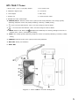
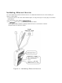
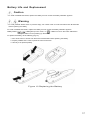
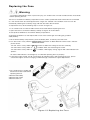
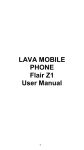
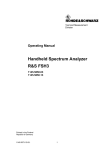
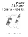
All-in-one Toner a Probe Kit User's Manual MT-7068 Maintenance Kit Congratulations on your purchase of MT-7068 Pro'sKit All-in-one Toner & Probe Kit. The Toner and Probe set is used to quickly trace and identify cables or wires within a group and also check the operation of phone lines. With proper use and care, this meter will provide many years of reliable service. Index Features 3 Applications 3 Advanced Features 3 Unpacking 4 Safety Information 4 MT-7068-T Toner. 5 MT-7068-R Probe 6 Locating and Isolating Cables 7 Locating Individual Wire Pairs with the MT-7068 Analog Function 8 Isolating Cables Cable Map Testing 9 10 Validating the Cable's Shield and Continuity Test 13 Validating Telephone Service and Polarity 14 Powering a Telephone Test Set 15 Validating Ethernet Service 16 Battery Life and Replacement 17 Replacing the Fuse 18 Maintenance 19 Trouble shooting 19 Specifications 20 Overview The MT-7068 All-in-one Toner & Probe Kit let you locate, isolate, and validate twisted pair (UTP, STP, Cat 5e, Cat 6), coax cables (RG6, RG58, RG59, and others for CATV/CCTV), USB and A/V signal, bare wire (such as speaker wire and security network wire), and Cat 3 telephone cabling. The Toner also lets you validate voice and data services. The MT-7068 All-in-one Toner & Probe Kit features let you use the Toner and Probe to validate and troubleshoot wiring on RJ11 /RJ45 cables and connectors, USB, F, BNC, and RCA connectors, and it also supplied with alligator clips to work with. The MT-7068 Toner detects telephone and Ethernet service, indicates polarity and active line numbers on voice circuits, and indicates active pair number on Ethernet circuits. The MT-7068 Toner and Probe also provide standard functions such as visual and audible signal strength indication, analog toning/detection, and continuity testing. The MT-7068 All-in-one Toner & Probe Kit is ideal for all maintenance fields of telecommunication, networking, datacom, Audio/Video, cable TV, and all weather cabling, etc. 2 Features: • Locates cables quickly and easily • Locates hidden cables • Isolates the right cable or pair fast • Overcome noise and save time • Tone on live networks safely and effectively • Verify conductor continuity with Cable Map • Identify and troubleshoot cable services Applications: • Copper cabling media, including shielded (STP) and UTP cable • 75 or 50 Ohm coaxial cable • Two conductor control, security, generic cabling • 10 Base-T or 10/100 Base-T datacom networks • POTS telecom serviceAdvanced Features Advanced Features • MT-7068 Toner generates 1 KHz compatible legacy analog tones that analog audio Probe can detect. • MT-7068 Toner provides two 1 KHz analog toning modes, one-note and two-note tones, for location and isolating cables. • MT-7068 Toner's multiple-level LEDs simplify signal interpretation in noisy environments. • In locating mode, the Probe's LEDs light up from 1 to 8 as the signal strength increases. The higher the number, the stronger the signal. • MT-7068 Probe also beeps in different tones to indicate good wiring, miswires, shorts, and opens in an efficient area between10 to 30 centimeters. • The 1 KHz analog toning mode is available at all connectors on the MT-7068-T Toner. • The MT-7068 feature also lets you use the Toner and Probe to validate and troubleshoot wiring on RJ11 /RJ45 cables and connectors, USB, F, BNC, and RCA connectors, and it also supplied with alligator clips to work with. • MT-7068 Toner detects telephone and Ethernet service, indicates polarity and active line numbers on voice circuits, and indicates active pair number on Ethernet circuits. • MT-7068 Toner and Probe also provide standard functions such as visual and audible signal strength indication, digital toning/detection, analog toning/detection, and continuity testing. • MT-7068 Toner features LED indicators for detecting the common wire resistance (>300Ω) for bad connections. • MT-7068 Toner identifies and diagnoses POTS with multi-line Telco detect polarity and ring indication (Line 1 and Line 2). • MT-7068 Toner detects telephone service and circuit polarity on its RJ11 and RJ45 jacks (Hand set and Butt set). • MT-7068 Toner identifies and diagnoses Ethernet link connectivity with NIC/hub indication. • MT-7068 Probe equipped with composite tip to reduce the risk of getting shock. • MT-7068 Toner and Probe equipped with easy tip replacement, and lanyards attachment point for hands-free operation. 3 Unpacking The MT-7068 products come with the accessories listed below. If an accessory is damaged or missing contact the place of purchase immediately. MT-7068 Maintenance Kit • MT-7068-T Toner with 9V battery and wrist strap • MT-7068-R Probe with 9V battery and wrist strap • 1 RJ45 (8 Pin) to RJ11 (6 Pin) patch cords • 2 RJ45 (8 Pin) to RJ45 (8 Pin) patch cords • F connector to BNC adapter, male to female • F connector to RCA adapter, male to female • Storage tool bag • User's manual Safety Information Table 1 describes the international electrical symbols used on the tester and in this manual. Table 1. International Electrical Symbols Warning: Risk of personal injury. See explanations in the manual. Caution: Risk of damage or destruction to equipment or software. See explanations in the manual. Warning: Risk of electric shock. Please keep eye on the status or function of the equipment while operating. This equipment not for connection to public communications networks, such as active telephone systems. Warning • Never use the Toner or Probe on circuits of more than 100V. • Never use the Toner, Probe, or test leads if they are damaged. Inspect the cases and test leads for damage before use. • Disconnect unused test leads and connectors from the Toner when testing telephone circuits. • Never open the case except to change the battery or the fuse; no user-serviceable parts are inside. • Turn off the Toner or Probe and disconnect all test leads before replacing the battery. • Use only a 9V battery, properly installed in the case, to power the Toner and Probe. • If this equipment is used in a manner not specified by the manufacturer, the protection provided by the equipment may be impaired. Caution • Avoid touching the Probe tip to patch panel connections and using the tip to dig into cable bundles. Doing so regularly may damage the Probe tip over time. • To avoid unreliable test results, replace the battery as soon as the low battery indication appears. 4 MT-7068-T Toner 1. RJ-45 (8Pin ) / RJ-11 (6/4/2pin) adaptor 3. Red/Black alligator clips 2. RJ-11patch cord 4. F connector 5. USB adapter 6. Wrist strap 7. Battery cap 8. 5-level function switch 9. Multiple-level LEDs CABLE MAP 10. SERVICE/TEL/Ω : Ethernet service status (open/closed circuit) indication; Line voltage (power) detecting, telephone service and polarity validating; continuity (>300Ω) testing. II. 12. : One-note tone LED indicator: 1KHz, one-note toning for Probe to detect. : Two-note tone LED indicator: 1KHz, two-note toning for Probe to detect. 13. CABLE: Cable mode. Works with Multiple-level Cable Map for showing LED lights and tones to indicate shorts, opens, and twisted pair cabling. 14. TEL/Ω: Line voltage (power) detecting, telephone service and polarity validating; continuity (>300Ω) testing 15. SERVICE: Ethernet service status (open/closed circuit) indication. 16. BAT LOW: Battery Low indication 17. Power OFF Figure 1 MT-7068-T Toner Diagram 5 MT-7068-R Probe I. Probe 2. USB adapter 3. F connector 4. Wrist strap 5. RJ-45(8Pin) / RJ-11(6/4/2pin) adapter 6. 02.5mm ear jack 7. Volume control 8. Battery cover 9. Indicates detection of MT-7068 signal and shows battery status at power-up 10. Multiple-level LED CABLE MAP, 1KHz analog tone signal indication I I . 5-level function switch 12. Power OFF 13. 1 KHz legacy analog signals detecting with audio indicator from speaker. 14. 1 KHz legacy analog signals detecting with audio indicator from earphone. 15. Identifies signals like shorts, opens, and twisted pair cabling with audio and this LED visual indicators. (Refer to 16. LED Cable Map) Identifies signals like shorts, opens, and twisted pair cabling with this LED visual indicator. (Refer to LED Cable Map) Figure 2 MT-7068-R Probe Diagram 6 Locating and Isolating Cables Locating and Isolating Terminated UTP/STP Cables with MT-7068 Warning • It is not intended to be used on live wires with a DC power source (e.g., live telephone lines), nor will it work on wire pairs that are carrying AC signals. Caution • To locate and isolate cables using the 1KHz analog toning mode, please avoid interference sources like electronic devices with adapter, induction coil, and motors nearby. White noise from MT-7068-R Probe is normal when your Toner is near any of the interference. If you cannot locate the signal on 2-conductor cables, the cable may be shorted. Please away from or turn off the electronic devices. • The position on the MT-7068 Toner and Probe lets you use the Probe to trace using an analog 1KHz tone. Use the Probe to isolate the tone source in the cable bundle or at the patch panel. • It is not necessary to touch the Probe's tip to the cabling or patch panel when searching for the Toner's signal. • Make sure the black alligator clip of the Toner is connecting to the ground before use. MT-7068 Toner provides two 1 KHz analog toning modes, one-note tone and two-note tone, for location and isolating cables. Both toning signals are available at all connectors on the Toner. 7 Locating Individual Wire Pairs with the MT-7068 Analog Function To locate cables, do the following (Figure 3): 1. Connect the black alligator clip of the Toner to the ground, and then connect the red clip to a jack or punch-down block as shown in Figure 3. 2. Turn the Toner's rotary switch to for a one-note tone or 3. Turn the Probe's rotary switch to flickers. . Turn the rotary to for a two-note tone. position when the LED 4. Use the Probe to find the general location of the tone at a cable rack, patch panel, or behind a wall. In locating mode, the Probe's LEDs light up in red from 1 to 8, then wrap back and light up from 1 to 8 again as the signal strength increases. 5. Adjust the Volume Control on the Probe to locate the wire pairs from 10cm to 30cm. Ground One-note Tone Two-note Tone Volume Control Volume Control Figure 3 Locating Cables Isolating Cables To isolate the tone source in the cable bundle or at the patch panel, do the steps as described in the previous section of "Locating Cables". 6. Strip the cable's shield to a length of between 30 to 45 centimeters and divide the wires into two parts. Do the wire dichotomy to isolate the cables to verify the signal of each part. If the beeper gets louder and LED lights up, you have located the position you are looking for. 7. Adjust the volume control from high to low to enable looking for a more difficult to identify wire. Narrowing the length from 30 to 10 centimeters will help to more accurately identify the wire pairs. 8. Repeat the steps of 6 and 7 to isolate the bundled cables. Loud Volume Control One-note Tone Volume Control Low Two-note Tone Volume Control Loud Figure 4 Isolating Cables Caution • If you cannot locate the MT-7068 signal on 2-conductor cables, the cable may be shorted or opened. Use the Cable Map Testing (Fig. 5) to test for shorts or opens on cables with RJ11 and RJ45 connectors. Use the Continuity Test (Fig. 8) to check for shorts or opens on coax and non-terminated cables. 9 Cable Map Testing: You can use the MT-7068 Toner or Probe to validate the cable map on RJ45, RJ11(6P/6C, 6P/4C, 6P/2C) jacks, USB, F(BNC, RCA) adapters and connectors. The cable map function finds the most common wiring faults on twisted pair cabling: shorts, opens, and crossed pairs. 1. Connect the MT-7068 Toner or Probe to RJ45 (8P/8C), RJ11 (6P/6C, 6P/4c, 6P/2C) jacks, or USB, F (BNC, RCA) connectors. 2. Turn the Toner's rotary switch to for beeper alarm or and wait until the LED flickers; then turn the Probe's switch to for mute indication. The Probe's LEDs and beeper indicate the cable map. Caution • Each LED that corresponding to an active pin flashes briefly, and then should light for about 1 second. The brief flash shows which LED is next in the sequence. • The Probe also beeps in different tones to indicate good wiring, miswires, shorts, and opens. • While testing Cable Map from 2 wires or less, the on and off tones may occur even if the LED lights normally. • Before Cable Map testing, repeat the procedures of "Locating Cables" on page 7 to identify the correct connector or wires on the other end of the cable if necessary. 10 3. Different connectors generate different LED and sound indications as shown in Figure 6. - RJ-45(8P/8C) LED indication: the MT-7068 Toner (from 1-8 seconds in sequence) is synchronized with the MT-7068 Probe CABLE MAP. - RJ-11(6P/6C, 6P/4C, 6P/2C) LED indication: MT-7068 Toner CABLE MAP, 6P/6C each second from 2 to 7 in sequence, 6P/4C each second from 3 to 6 in sequence, 6P/2C each second from 4 to 5 in sequence is synchronized with the MT-7068 Probe CABLE MAP. If it encounters an empty line, the indication will cease. - USB LED indication: the MT-7068 Toner (each second from 1-4 seconds) is synchronized with the LED on the MT-7068 Probe. Each LED indicator counts for one second. The USB indication will skip and pause for 4 seconds from LED #5 - #8. - F (BNC, RCA) LED indication: the MT-7068 Toner (each second from 1-2 seconds) is synchronized with the LED on the MT-7068 Probe. Each LED indicator counts for one second. The F connector indication will skip and pause for 6 seconds from LED #3 - #8. MT-7068-T Toner Cable Map MT-7068-R Receiver Cable Map RJ-45 (8P/8C) RJ-11 (6P/4C) USB F (BNC, RCA) Figure 6 Differenct Connector's Cable Map 11 4. You can use the MT-7068 Toner and Probe to validate the cable map on RJ11 and RJ45 connectors. The cable map function finds the most common wiring status on twisted pair cabling: good, shorts, opens, and crossed pairs as shown in Figure 7. • Good wiring: Each LED that corresponding to an active pin flashes briefly and in a stairway order. • Shorts: If two LEDs turn on for 1 second at the same time, those two pins are shorted together. If more than 2 wires are shorted together, the LEDs for the shorted pins indicate opens. • Opens: If an LED flashes briefly, then no LEDs turn on, that pin is open. • Crossed pairs: If one LED flashes briefly, then another LED lights for one second, the wire for the first LED is crossed pairs to the pin for the second LED. 5. Each LED that corresponding to an active pin flashes briefly, it should light for about 1 second. The brief flash shows which LED is next in the sequence. MT-7068-T Toner Cable Map MT-7068-R Receiver Cable Map 1-8 Good 3,4 Shorts 3 Opens 3,4 Crossed Pairs Figure 7 Good Wiring, Shorts, Opens, Crossed Pairs Validating the Cable's Shield and Continuity Test DANGER • Remove the battery door and disconnect the battery from the Probe. To validate cable shield during cable map tests, do the following as shown in Figure 8: 1. Connect the Toner to the circuit as shown in Figure 8. Connect the test leads to the telephone punch-down blocks, RJ11, and RJ45 jacks. 2. Turn the Toner's rotary switch to 3. The LEDs of the Toner indicates the status as below: Green light: cable shielded and connected (Resistance<300D). No light: no shield and no service (Resistance>300D). Validating the Cable's Shield Testing for Continuity OR OR = TEL/Ω ο No Light Open: Resistance >300Ω = TEL/ Ω Green Short: Resistance < 300Ω Figure 8 Continuity Test 13 Validating Telephone Service and Polarity The Toner detects telephone service and circuit polarity on its banana, RJ11 and RJ45 jacks. To validate telephone service and polarity, do the following as Figure 9 shown below. 1. Connect the Toner to the circuit as shown in Figure 9. Connect the test leads to the telephone punch-down blocks, RJ11, and RJ45 jacks. 2. Turn the Toner's switch to 3. The LEDs of the Toner indicates the status as below: Green light: Red test lead at positive (+) polarity Black test lead at negative (-) polarity Red light: Red test lead at negative (-) polarity Black test lead at positive (+) polarity Telephone Pounch-down Block Red: Red test lead (- polarity) Black test lead (+ polarity) Green: Red test lead (+ polarity) Black test lead (- polarity) Figure 9 Validating Telephone Service and Po 14 Powering a Telephone Test Set Caution When powering the telephone test sets, the toner needs more power consumption to generate the device. 9V alkaline battery (NEDA 1604A or IEC6LR61) is recommended for this operation. The Toner can supply 6V into a 600Ω circuit to power telephone test sets (Hand set/Butt set) when Central Office battery power is not present. (Fig 10) 1. Connect the Toner to the voice circuit as shown in Figure 10. 2. Turn the Toner's rotary switch to 3. The LED indicator lights green; the Toner is supplying 6V into a 600Ω circuit to power telephone test sets (Hand set/Butt set). Green Red test lead (+ polarity) (DC6V) Black test lead (- polarity) Figure 10 Powering a Telephone Test Set Validating Ethernet Service The Toner detects link pulses for Ethernet service. To validate the Ethernet service, do the following as Figure 11 shown below. 1. Connect the Toner to the circuit of RJ45 Ethernet jack. Or using RJ45 (8 pin to 8 pin) plug to connect the Ethernet jack. 2 Turn the Toner's rotary switch to 3. The LEDs of the Toner indicates the status as below: Green lights (10HD) or flashes (100HD) indicate the Toner is connected to a network. No light indicate non-Ethernet voltage. RJ-45 Ethernet Jack SERVICE Green lights or flashes indicate the toner is connected to a network. No Light indicate non-Ethernet voltage Figure 11 Validating Ethernet Service Battery Life and Replacement Caution • To avoid unreliable test results, replace the battery as soon as the low battery indication appears. Warning • To avoid possible electric shock or personal injury, turn off the Toner or Probe and disconnect all test leads before replacing the battery. To avoid unreliable test results, replace the battery as soon as the low battery indication appears. Battery Status: LED lights up on the Toner, or LED turns red on the Probe indicate the voltage is under 6.5V for powering up the device. To replace the battery, do the following (Fig 12): 1. Turn off the Toner or Probe and disconnect all test leads before replacing the battery. 2. Properly installed in the case to power the Toner and Probe. 3. Use only a 9V (6FF22) battery. Figure 12 Replacing the Battery 17 Replacing the Fuse Warning • To avoid possible electric shock or personal injury, turn off the Toner or Probe and disconnect all test leads before replacing the fuse. The fuse is located in the battery compartment and is used to protect the tester if the leads are connected to a "live circuit" when the continuity/resistance ranges are selected. The condition of the fuse can be checked by selecting the continuity range, with the test leads disconnected. To replace the fuse, do the following steps as shown in Figure 13: 1. Turn off the Toner or Probe and disconnect all test leads before replacing the fuse. 2. Open the cover to remove the battery carefully as Figure 13 shown below. 3. Use tip #0 screwdriver to unscrew the battery compartment. 4. Remove the blown fuse and replace with a fuse of the correct type and rating (05 χ L20mm 250V/250mA). 5. Re-screw the battery compartment, place the battery back, and finally close the cover. 6. Turn the Toner's rotary switch to phone service. Turn the Toner's rotary switch to position to detect Ethernet service status and tele position to detect line voltage and to test continuity. Turn the Probe's rotary switch to " " to detect 1KHz, two-note toning for Probe. Turn the Probe's rotary switch to " speaker. " to detect 1 KHz legacy analog signals with audio indicator from All above LED indicators should light up as it did after replacing the fuse properly. 7. If the Toner and/or Probe are still not functional by following step 6 after replacing the fuse, please contact the original store for arranging an RMA through our technical support department. 1 Turn off the Toner or Probe and disconnect all test leads before replacing the fuse 2.Remove the battery 3.Remove the screws 4.Remove the fuse Figure 13 Replacing the Fuse Maintenance Warning • Turn off the Toner or Probe and disconnect all test leads before replacing the battery. Caution • To avoid damaging the case, do not use solvents or abrasive cleansers. • Clean the case with a soft cloth dampened with water or a mild soap solution. Trouble shooting • If the MT-7068 Probe volume is too low when using the 1KHz signal to validate and isolate electric wires: 1. Check to see that the Probe rotary switch is properly positioned and that there is no low battery indication. 2. Turn the Probe volume to Maximum. 3. Check to ensure the Toner rotary switch is properly positioned and that there is no low battery indication. 4. Check if the Toner black alligator clip is connected to the ground and the red alligator clip is properly connected to the testing wire, the adapter or the patch panel. • If the light displays incorrectly when using the CABLE MAP to test: 1. Re-check that the Toner and Probe rotary switches are properly positioned and that there is no low battery indication. 2. Use the RJ-45(8Pin) to RJ-45(8Pin) patch cord that provided with the package to run a simulated test. 3. Connect the testing wire with both end connectors and then reconnect it properly. 19 Specifications Environmental and Regulatory Specifications Operating temperature 0 ° C ~ 4 0 ° C (32°F ~ 104°F) Operating relative humidity (% RH without condensation) 95% (10°C - 35°C ; 50°F - 95°F) 75% (35°C - 40°C ; 95° F - 104° F) uncontrolled < 50°F (10°C) Altitude 3000 m EMC EN 55022, EN 55024 MT-7068-T Toner Tone frequency 1KHz Tone mode One-note / Two-note Output power 15.5Vp-p Compatible connectors RJ-45/RJ-11/USB/F/BNC/RCA/Alligator Clips Continuity test <300Ω Talk battery voltage 6V into 600Ω Function selection 5-position rotary switch Cable Map indication 8 LED indicators Voltage protection 100V Low battery display 6.5V Battery type 9V (6F22) Dimension (LxWxD) 140x70x30mm Weight 203g (with battery) MT-7068-R Probe Frequency 1KHz Compatible connectors RJ-45/RJ-11/USB/F/BNC/RCA Ear jack 1 Signal status indication 8 LED indicators Cable map indication 8 LED indicators Low battery display 6.5V Battery type 9V (6F22) Dimension (LxWxD) 250x52x33mm Weight 180g (with battery)