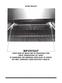
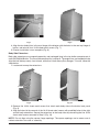
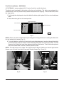
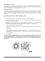
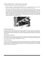
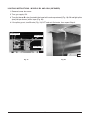
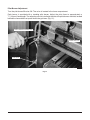
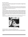
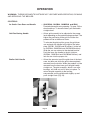
1
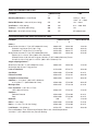
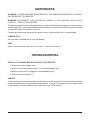
INSTALLATION &
OPERATION MANUAL
HEAVY DUTY GAS BROILERS
CERAMIC MODELS
GHCBO40
GHCB44
GHMCB44
GHCB1
GHCB2
SUNGLOW MODELS
IR2
IR44
MODEL GHCBO40
For additional information on Vulcan-Hart Company or to locate an authorized
parts and service provider in your area, visit our website at www.vulcanhart.com
VULCAN-HART
COMPANY,
P.O.
BOX
696,
LOUISVILLE,
KY
40201-0696,
TEL.
(502)
778-2791
FORM 30533 Rev. E (Sept. 2002)
IMPORTANT FOR YOUR SAFETY
THIS MANUAL HAS BEEN PREPARED FOR PERSONNEL QUALIFIED TO INSTALL GAS
EQUIPMENT, WHO SHOULD PERFORM THE INITIAL FIELD START-UP AND
ADJUSTMENTS OF THE EQUIPMENT COVERED BY THIS MANUAL.
POST IN A PROMINENT LOCATION THE INSTRUCTIONS TO BE FOLLOWED IN THE
EVENT THE SMELL OF GAS IS DETECTED. THIS INFORMATION CAN BE OBTAINED
FROM THE LOCAL GAS SUPPLIER.
IMPORTANT
IN THE EVENT A GAS ODOR IS DETECTED, SHUT DOWN
UNITS AT MAIN SHUTOFF VALVE AND CONTACT THE LOCAL
GAS COMPANY OR GAS SUPPLIER FOR SERVICE.
FOR YOUR SAFETY
DO NOT STORE OR USE GASOLINE OR OTHER FLAMMABLE
VAPORS OR LIQUIDS IN THE VICINITY OF THIS OR ANY
OTHER APPLIANCE.
WARNING: IMPROPER INSTALLATION, ADJUSTMENT,
ALTERATION, SERVICE OR MAINTENANCE CAN CAUSE
PROPERTY DAMAGE, INJURY OR DEATH. READ THE
INSTALLATION, OPERATING AND MAINTENANCE
INSTRUCTIONS THOROUGHLY BEFORE INSTALLING OR
SERVICING THIS EQUIPMENT.
IN THE EVENT OF A POWER FAILURE, DO NOT ATTEMPT TO
OPERATE THIS DEVICE.
–2–
STOP BOLTS
IMPORTANT
STOP BOLTS MUST BE IN POSITION FOR
SAFE OPERATION OF GRID.
IF DAMAGED OR MISSING, REPLACE AT ONCE.
DO NOT OPERATE GRID WITHOUT BOLTS.
–3–
TABLE OF CONTENTS
GENERAL .............................................................................................................................................5
INSTALLATION ....................................................................................................................................5
Unpacking - All Broiler Models .......................................................................................................5
Location - All Models .......................................................................................................................6
Installation Codes and Standards - All Broiler Models .................................................................6
Unstacking and Stacking - Model GHCB2 ....................................................................................7
Draft Hood Installation - GHCB40 or GHCB44 .............................................................................8
Leveling and Connecting Manifolds - All Models ........................................................................ 11
Gas Connections ......................................................................................................................... 13
Testing the Gas Supply System ................................................................................................. 13
Flue Connections ......................................................................................................................... 13
Electrical Connections ................................................................................................................. 14
Minimum Bypass Setting - Model GHCBO40 Oven .................................................................. 14
Lighting Instructions - Models GHCB44, GHCBO40 and GHMCB44 Broilers ........................ 14
Lighting Instructions - Model GHCBO40 Ovens ........................................................................ 15
Lighting Instructions - Models GHCB1 and GHCB2 .................................................................. 16
Lighting Instructions - Models IR2 and IR44 (Infrared) ............................................................. 17
OPERATION ...................................................................................................................................... 20
Controls ........................................................................................................................................ 20
Before First Use ........................................................................................................................... 21
Cooking ........................................................................................................................................ 22
Using the Broiler .......................................................................................................................... 22
Cooking Chart - GHCBO40 Oven Only ..................................................................................... 23
Cleaning ........................................................................................................................................ 25
MAINTENANCE ................................................................................................................................. 26
Lubrication .................................................................................................................................... 26
Vent ............................................................................................................................................... 26
TROUBLESHOOTING ...................................................................................................................... 26
Checks to be Made Before Calling the Servicer ........................................................................ 26
Service ......................................................................................................................................... 26
–4–
Installation, Operation and Care of
CERAMIC AND SUNGLOW HEAVY DUTY BROILERS
SAVE THESE INSTRUCTIONS
GENERAL
The manufacturer suggests that you thoroughly read this entire manual and carefully follow all of the
instructions provided.
Your Vulcan Sunglow or Ceramic Broiler is produced with quality workmanship and material. Proper
installation, usage and maintenance of your broiler will result in many years of satisfactory performance.
INSTALLATION
UNPACKING - ALL BROILER MODELS
This broiler was inspected before leaving the factory. The transportation company assumes full
responsibility for safe delivery upon acceptance of the shipment. Immediately after unpacking, check
for possible shipping damage. If the broiler is found to be damaged, save the packaging material and
contact the carrier within 15 days of delivery.
Remove the small wood slats and wire used to hold burners and broiler grid in place.
Before installing, verify that the electrical service and type of gas supply (natural or propane) agree with
the specifications on the rating plate.
Models
Rating Plate Location
IR2 & IR44
Cabinet bottom, front right-hand side
GHMCB44
Front manifold cover
GHCB44
Inside cabinet door panel
GHCB1 & GHCB2
Cabinet bottom, front left-hand side
GHCBO40
Oven: behind the kick panel attached to the left side of the oven
burner box front shield, positioned behind the bell crank
Broiler: Front manifold cover
If the supply and equipment requirements do not agree, do not proceed with the installation. Contact
your dealer or Vulcan-Hart immediately.
–5–
LOCATION - ALL MODELS
The equipment area must be kept free and clear of combustible substances. The broiler, when installed,
must have minimum clearance from combustible and noncombustible construction of:
Models
Minimum Clearance to Combustible Construction
GHCBO40, GHCB44 & GHMCB44 . . . . . . . .
6" (152.4 mm) sides and rear
IR44 . . . . . . . . . . . . . . . . . . . . . . . . . . . . . . . . .
0" sides and 4" (101.6 mm) rear
GHCB1 & GHCB2 . . . . . . . . . . . . . . . . . . . . . .
4" (101.6 mm) sides and rear
IR2 . . . . . . . . . . . . . . . . . . . . . . . . . . . . . . . . . .
0" sides and 4" (101.6 mm) rear
The installation location must allow adequate clearances for servicing and proper operation. A minimum
front clearance of 48" (121.9 cm) is required.
The broiler must be installed so that the flow of combustion and ventilation air will not be obstructed.
Adequate clearance for air openings into the combustion chamber must be provided. Make sure there
is an adequate supply of air in the room suitable for the amount of combustion gas feeding the broiler
burners.
INSTALLATION CODES AND STANDARDS - ALL BROILER MODELS
Install this equipment in accordance with:
In the United States
1. State and local codes, or in the absence of local codes, with:
2. National Fuel Gas Code, ANSI-Z223.1 (latest edition), available from the American Gas Association,
Inc., 1515 Wilson Blvd., Arlington, VA 22209.
3. National Electrical Code ANSI/NFPA70 (latest edition) (if applicable).
In Canada
1. Local codes.
2. CSA Standard C22.2 No. 3 Electrical Features of Fuel Burning Equipment (latest edition).
3. CAN/CGA-B149.1 National Fuel Gas Code (latest edition), available from The Canadian Gas
Association, 178 Rexdale Rd., Etobicoke, Ontario, Canada M9W 1R3.
For an appliance equipped with casters, instructions that (1) the installation shall be made with a
connector that complies with the Standard for Connectors for Movable Gas Appliances, ANSI Z21.69
or Connectors for Moveable Gas Appliances, CAN/CGA-6.16 , and a quick-disconnect device that
complies with the Standard for Quick-Disconnect Devices for Use With Gas Fuel, ANSI Z21.41 or
Quick Disconnect Devices for Use with Gas Fuel, CAN1-6.9 , (2) adequate means must be provided
to limit the movement of the appliance.
–6–
Provide a gas line strain relief to limit movement of the
broiler, without depending on the connector and any quickdisconnect device or its associated piping to limit the
broiler movement. Attach the strain relief to the rear of the
broiler (Fig. 1).
If disconnection of the strain relief is necessary, turn off the
gas supply before disconnection. Reconnect the strain
relief before turning the gas supply on and returning the
broiler to its original installation position.
CONNECT GAS
LINE STRAIN
RELIEF HERE
PL-51216
Fig. 1
UNSTACKING AND STACKING - MODEL GHCB2
Read all instructions carefully before unstacking or stacking broilers.
The height of Models GHCB2 and IR2 sometimes prohibits entry through the kitchen facility doorway.
For this reason, two 3 3/4 x 11/2 x 3/64" (95 mm x 38 mm x 1.2 mm), aluminized stacking straps are shipped
with each broiler for ease of top section disassembly.
Broilers Shipped Pre-stacked
1. Remove top section finishing back.
2. From oval slots inside finishing back of the top section, remove two 10-24 bolts which connect
the top and bottom sections (Fig. 2).
3. Remove drip pan and disassemble two 10-24 bolts, one to the left and one to the right of the inside
drip pan area, behind the top section front frame (Fig. 3).
PL-41717
PL-41718
Fig. 2
Fig. 3
4. Carefully remove broiler top section from the bottom section.
5. Leaving the lower far-left and right holes open, reassemble the top finishing back onto the top.
–7–
Broilers Shipped in Two Pieces for Restacking
The incorporation of the stacking straps will eliminate the use of the two oval slots, one to the left and
one to the right, behind the finishing back of the top section. (See Step 2 under Broilers Shipped PreStacked.)
1. Position broilers as near to installation location as
possible. Remember to allow enough room to complete
stacking procedures.
2. Carefully lift top section and rest it evenly onto the
bottom section.
STACKING STRAP
3. Remove top section drip pan. Align two holes, one to
the left and one to the right of the upper drip pan area,
behind the broiler front frame. Insert two 10-24 bolts
and assemble the top section to the bottom section.
4. Replace the drip pan.
5. From rear of broiler, remove two 10-24 bolts from the
upper corner of the left- and right-hand bottom section
finishing back.
6. Using four 10-24 bolts, assemble the stacking strap
as shown in Fig. 4. This will complete the stacking
procedure.
PL-56559
Fig. 4
DRAFT HOOD INSTALLATION - GHCB40 OR GHCB44
All GHCB40's and GHCB44's come equipped with a hood flue diverter that is packaged and laying in
the top broiler compartment. This flue diverter must be attached to the unit at the time of installation,
following the steps below:
1. If the diverter has protective plastic covering the assembly, remove all the plastic.
2. Place the diverter on top of the unit covering the flue (Fig. 5).
3. Remove four 10-24 sheet metal screws from the top rear flange of the broiler (Fig. 6).
HOOD
FLUE
DIVERTER
FLUE
SCREWS
PL-41719-1
PL-41720-1
Fig. 5
Fig. 6
–8–
PL-41721
PL-41722
Fig. 7
Fig. 8
4. Align the four holes/slots in the rear flange of the diverter with the holes in the rear top flange of
broiler, and reinstall four 10-24 sheet metal screws (Fig. 7).
5. Diverter installation is now complete (Fig. 8).
Body Side Extensions
Body side extensions are wrapped separately and packaged lying in the top broiler compartment of
each GHCB40/44 Broiler. The use of these extensions is optional. The extensions are intended to help
align the broil battery evenly, front to back, with other Vulcan Heavy Duty Ranges. To install, follow the
steps below:
1. Locate and unwrap the extensions.
SCREWS
PL-41723-1
PL-41724
Fig. 9
Fig. 10
2. Remove five 10-24 sheet metal screws that attach each body side to the broiler back panel
(Fig. 9).
3. Align the holes left by removal of the 10-24 sheet metal screws with predrilled holes in the right
and left body extensions. Secure the extensions to the body sides by reinstalling the five 10-24
sheet metal screws removed in Step 2 (Fig. 10).
NOTE: Do not align using the square flange openings. The square openings are to access use of
ratchet extensions for ease of assembly.
–9–
Fire Brick Installation - GHCB40/44
All GHCB40/44's come equipped with 12 center fire bricks and 8 side bricks.
The bricks must be placed in the broiler at the time of installation. The bricks are packaged in a
cardboard box, which is placed in the top broiler compartment for shipping. To install the bricks, follow
the steps below:
1. Cut through the shipping wire strap that holds the broiler grid in place if this has not already been
done.
2. Place the broiler grid into its lowest position.
PROTRUDING POINTS
SIDE FIRE BRICK
CENTER FIRE BRICK
SIDE BRICK RIDGE
PL-41725-1
Fig. 11
NOTE: Bricks are to be installed with the protruding points facing downward. Installing the side bricks
first will make the job easier (Fig. 11)
3. To install side brick, with brick in hand, points protruding downward, reach up through the broiler
grid compartment and rest the brick in the bracketing along side of the cast iron burners. It will be
necessary to tilt the bricks to get them between the burner and bracket. Then lift the brick up above
the burner and bracket, and set it carefully down in place.
NOTE: The side bricks have a ridge. This ridge should set down inside the far left and right bracket
flanges; you will install four bricks along each bracket flange (Fig. 12 and 13).
SIDE BRICK RIDGE
BRACKET FLANGE
BURNER
PL-41726
PL-41727-1
Fig. 12
Fig. 13
– 10 –
4. Center bricks are installed towards the center of the broiler in three rows of four bricks each. Install
the center bricks similar to that of the side bricks in Step 3. Angle the bricks and slip them up
between the burners, then set them in place.
NOTE: The center bricks are to be installed to rest between two burners on the vertical burner flange
(Fig. 14 and 15).
PL-41728
PL-41729
Fig. 14
Fig. 15
LEVELING AND CONNECTING MANIFOLDS - ALL MODELS
The IR2 Model is not designed to be batteried to other heavy duty equipment. After leveling the IR2
Model, as described in Step 2, proceed to Gas Connections.
1. Place the broiler in its exact position or battery lineup.
2. Using a carpenter level, level the broiler from front to rear and from side to side. Unless the broilers
are level, they will not give proper cooking results, and equipment being batteried will not draw up
tight.
As of January 1998, Vulcan-Hart appliances use Ward gas unions instead of Stockham gas unions.
If you are installing a new battery range to an existing field appliance, the union on the existing field
appliance must be checked against the union being used on the new range. The union manufacturer’s
name around the face surface of the union nut must match. The new range has been shipped with a
Ward union. If the old appliance has something different, i.e., Stockham, it must be replaced with a Ward
union. Failure to replace this union could result in a gas leak (Fig. 16).
If a Ward gas union is needed for installation, it may be obtained through the Vulcan-Hart Parts
Department.
– 11 –
Fig. 16
Questions or concerns regarding the installation procedures may be addressed by calling the VulcanHart Service Department (502) 778-2791.
3. Engage union nut on manifold pipe of broiler with the male fitting on the next broiler, and draw up
union hand-tight. Be sure broilers butt both front and rear.
NOTE: Broilers are mounted on a steel, skid-type base, so a crowbar may be used to jockey units. If
the manifolds do not line up, then the broilers are not level.
4. Continue to level up and connect manifold pipe until all broilers in the battery are connected, then
tighten all manifold unions gas-tight.
– 12 –
GAS CONNECTIONS
CAUTION: All gas supply connections and any pipe joint compound used must be resistant to
the action of propane gases.
Connect gas supply to the broiler(s). Make sure the pipes are clean and free of obstructions, dirt and
piping compound.
Codes require that a gas shutoff valve be installed in the gas line ahead of the broiler.
Natural gas broilers and propane gas broilers are equipped with fixed orifices and no adjustment is
necessary.
Model IR Broilers for operation on natural or propane gas are also equipped with a factory-preset
pressure regulator, with an outlet pressure of 6" (1.49 mb) Water Column for natural gas supply and
10" (2.49 mb) Water Column for propane gas supply. No further adjustment should be required.
Models GHCBO40, GHCB44 and GHMCB44 also require a pressure regulator (not supplied). The
regulators must have:
•
A.G.A. design certification.
•
Enough regulation capacity for the total connected gas load.
•
Pressure adjustment range to allow adjustment for the manifold pressure marked on the rating
plate.
Unless the manifold pressure on all connected broilers is the same, a separate regulator must be
supplied for each broiler having different manifold pressures.
If the front plates do not line up perfectly, adjust by using bolts under the front plate.
WARNING: PRIOR TO LIGHTING, CHECK ALL JOINTS IN THE GAS SUPPLY LINE FOR LEAKS.
USE SOAP AND WATER SOLUTION. DO NOT USE AN OPEN FLAME.
Ensure that burner heads are connected.
After piping has been checked for leaks, all piping receiving gas should be fully purged to remove air.
TESTING THE GAS SUPPLY SYSTEM
When test pressures exceed 1/2 psig (3.45 kPa), the broiler and its individual shutoff valve must be
disconnected from the gas supply piping system.
When test pressures are 1/2 psig (3.45 kPa) or less, the broiler must be isolated from the gas supply
system by closing its individual manual shutoff valve.
FLUE CONNECTIONS
DO NOT obstruct the flow of flue gases from the flue duct located on the rear of the broiler. It is
recommended that the flue gases be ventilated to the outside of the building through a ventilation
system installed by qualified personnel.
From the termination of the broiler flue vent to the filters of the hood venting system, an 18" (457 mm)
minimum clearance must be maintained.
Information on the construction and installation of ventilating hoods may be obtained from the standard
for "Vapor Removal from Cooking Equipment," NFPA No. 96 (latest edition), available from the National
Fire Protection Association, Batterymarch Park, Quincy, MA 02269.
– 13 –
ELECTRICAL CONNECTIONS
WARNING: ELECTRICAL AND GROUNDING CONNECTIONS MUST COMPLY WITH THE
APPLICABLE PORTIONS OF THE NATIONAL ELECTRICAL CODE AND/OR OTHER LOCAL
ELECTRICAL CODES.
WARNING: DISCONNECT THE ELECTRICAL POWER TO THE MACHINE AND FOLLOW
LOCKOUT / TAGOUT PROCEDURES.
If the broiler is not equipped with a grounding plug and electrical supply is needed, ground the broiler
by using the ground lug provided (refer to the wiring diagram located inside the lower cabinet section).
Infrared broilers Models IR1, IR2 and IR44 are equipped with a 4' (122 cm) long supply cord.
WARNING: APPLIANCES EQUIPPED WITH A FLEXIBLE ELECTRIC SUPPLY CORD ARE
PROVIDED WITH A THREE-PRONG GROUNDING PLUG. IT IS IMPERATIVE THAT THIS PLUG
BE CONNECTED INTO A PROPERLY GROUNDED THREE-PRONG RECEPTACLE. IF THE
RECEPTACLE IS NOT THE PROPER GROUNDING TYPE, CONTACT AN ELECTRICIAN. DO
NOT REMOVE THE GROUNDING PRONG FROM THIS PLUG.
Do not connect broiler to electrical supply until after gas connections have been made.
MINIMUM BYPASS SETTING - MODEL GHCBO40 OVEN
Adjust the oven pilot and burner for proper adjustment of minimum bypass setting. See instructions
under LIGHTING INSTRUCTIONS - MODEL GHCBO40 OVEN.
LIGHTING INSTRUCTIONS - MODELS GHCB44, GHCBO40 AND GHMCB44 BROILERS
1. Remove au gratin oven bottom, baffle and burner box cover.
2. Remove oven bottom and baffles (Model GHCBO40 only).
3. Remove manifold panel.
4. Turn gas supply ON.
5. Place the ceramics, with the projections down, to the rear of broiler burners. The lugs on the
burners will properly position themselves. The ceramics are sized at the factory.
6. Place the au gratin oven baffle and bottom, but leave the burner box cover off.
7. Turn the gas valve ON and allow air in the line to be exhausted. When gas begins to flow, turn gas
valve OFF and wait 5 minutes before lighting pilots and burner with a taper. The burner flame
should be sharp when the broiler is cold, with a blue cone of flame about 3/4" (19 mm) long on natural
gas and 1/2" (12.7 mm) long on propane gas. The flame will soften out and curl around the ceramics
as the broiler gets hot. The length of the flame is determined by the adjustment of the nozzle. The
sharpness of the flame is determined by the air shutter adjustment.
8. Adjust broiler pilots at the pilot valve on the left end of the pilot manifold pipe. Adjust the flame to
approximately 3/4" (19 mm) long. Replace the burner box front.
9. Replace manifold panel and other parts that had been removed.
NOTE: Be sure pilots remain lit after installation.
– 14 –
Carbonization of Ceramics
If the ceramics take on a black sooty accumulation, the burners are receiving an insufficient amount
of air. Open the air shutters further to provide more air. If carbonization occurs during initial adjustment,
it will burn off as soon as proper adjustment is achieved.
Burner Performance
If, after a period of satisfactory operation, the burner flame characteristics should change or the length
of burner flame should be reduced, either the air mixer opening or the gas valve orifice has become
restricted. The burners should be cleaned every 60 days, or more often as required, by an authorized
servicer.
LIGHTING INSTRUCTIONS - MODEL GHCBO40 OVENS
1. If the oven pilot is out, turn the burner OFF. Wait 5 minutes before relighting.
2. Depress the red ignition button located on the oven control panel and ignite the pilot. Hold
60 seconds until pilot remains ON.
3. Adjust the oven pilot and burner for proper adjustment of minimum bypass setting. This
adjustment must be made at the time the broiler is installed. To adjust this flame:
•
Be sure oven burner pilot flame is ignited.
•
With oven cold, slowly turn dial (Fig. 17) counterclockwise from OFF until main burner gas
snaps on.
•
Remove dial.
•
With a screwdriver, turn bypass adjustment screw (Fig. 17) counterclockwise to increase the
bypass flame, or clockwise to decrease it, until flame over entire burner is approximately 1/8"
(3.175 mm) high.
•
Replace dial.
CAUTION: While making this adjustment, if the oven should become heated while the dial is set
at a low range (below 350°F [177°C]), the bypass flame will shut off completely. If this occurs,
turn dial counterclockwise slowly until bypass gas snaps on. Then check bypass adjustment as
stated above.
DIAL
BY-PASS
ADJUSTMENT
SCREW
POINTER "A"
350
BA 40
KI
N
MODEL
FDO
0
0
30
250
0
500
200LO
450
ROA
ST
G
SCREW
CLEARANCE
SLOTS
15
CALIBRATION
PLATE
CALIBRATION
SCREWS
PL-56560
Fig. 17
– 15 –
LIGHTING INSTRUCTIONS - MODELS GHCB1 AND GHCB2
1. Remove burner box front cover and turn gas supply ON.
2. Place the ceramics, with the projections down, to the rear of broiler burners. The lugs on the
burners will properly position themselves. The ceramics are sized at the factory.
3. Turn the gas valve ON and allow air in the line to purge. When gas begins to flow, turn gas valve
OFF and wait 5 minutes before lighting the pilots. The pilot flame should be about 3/4" high and
burner with a taper. The burner flame should be high enough to touch the ceramic bricks. The
length of the burner flame is determined by the adjustment of the burner nozzle. When the burner
flame is cold, the flame should appear as a sharp blue cone. As the flame gets hot, it will soften
in color and begin to curl around the ceramics. The sharpness of the flame is controlled by the
setting of the burner air shutter (Fig. 18).
PL-41730
Fig. 18
Pilot Burner Adjustment
Turn the pilot burner valve (located in the lower compartment) ON. Each burner is provided with a
standing pilot burner. Adjust the pilot flame to approximately 3/4" (19 mm) flame height. The adjusting
valve is installed in the inlet of the pilot burner manifold, located behind the removable front panel above
the grid area.
Carbonization of Ceramics
If the ceramics take on a black sooty accumulation, the burners are receiving an insufficient amount
of air. Open the air shutters further to provide more air. If carbonization occurs during initial adjustment,
it will burn off as soon as proper adjustment is achieved.
Burner Performance
If, after a period of satisfactory operation, the burner flame characteristics should change or the length
of burner flame should be reduced, either the air mixer opening or the gas valve orifice has become
restricted. The burners should be cleaned every 60 days, or more often as required, by an authorized
servicer. This is not a warranty call.
– 16 –
LIGHTING INSTRUCTIONS - MODELS IR2 AND IR44 (INFRARED)
1. Remove burner box cover.
2. Turn gas supply ON.
3. Turn pilot burner B valve (located in the lower left-hand compartment) (Fig. 19) ON and light pilots
(one pilot per burner) with a taper (Fig. 20).
4. If the pilots go out, turn B valve (Fig. 19) OFF and wait 5 minutes, then repeat Step 3.
BURNER B VALVE
TOGGLE SWITCH
INDICATOR LIGHT
PL-41731-1
PL-41732
Fig. 19
Fig. 20
– 17 –
Pilot Burner Adjustment
Turn the pilot burner B valve ON. The valve is located in the lower compartment.
Each burner is provided with a standing pilot burner. Adjust the pilot flame to approximately a
3
/4" (19 mm) flame length. The adjusting valve is installed in the inlet of the pilot burner manifold, located
behind the removable front panel above the grid area (Fig. 21).
PILOT BURNER ADJUSTMENT VALVE
BURNER ORIFICE TIP
HI-LOW VALVE
PL-41733-1
Fig. 21
– 18 –
Main Burner Adjustment
Orifices (1 per burner) are located in the front of each burner venturi, behind a removable front panel
above the grid area. Each burner is controlled by either a "Hi-Lo" Valve (IR2), or a "Hi-Med-Lo" Valve
(IR44) and an orifice (Fig. 22).
Main Burner Valve Adjustment
The "high" position is fixed and cannot be adjusted. The "low" position may be adjusted to obtain the
minimum stable flame. In order to adjust the "low" setting, turn the knob to "low," remove the knob and
rotate the adjusting screw (located in the center shaft of the valve) clockwise to decrease and
counterclockwise to increase burner flame (see Fig. 21).
Air Adjustment
Although air adjustment is made at the factory before the broiler is shipped, it may be necessary to
readjust after installation is made. All of the air required for combustion is supplied by the blower through
an air duct on the left side. A single air adjustment is provided at the air intake to the blower (IR44) or
behind each "right" burner valve (IR2). No other adjustment is provided or necessary (Figs. 21 and 22.)
Burners or infrared generators should burn with uniform radiant heat and without any flame curling
around the sides of the burner. If flame curls around the burner, the air supply needs to be increased;
if burner radiates with a bright orange glow with darkened areas throughout, the air supply should be
decreased.
(Model IR44 Only) — Insufficient air may keep the pressure switch opened and the solenoid valve will
not open to supply gas to the broiler. Increase the air supply to obtain proper operation.
PL-41734
Fig. 22
Carbon Accumulation — Burner Screen (Infrared Broilers Only)
If the burner screens take on a black sooty accumulation, the burners are not receiving enough air.
Increase the air supply at the blower inlet. The carbon will burn off as soon as the proper adjustment
is made.
– 19 –
OPERATION
WARNING: THE BROILER AND ITS PARTS ARE HOT. USE CARE WHEN OPERATING, CLEANING
AND SERVICING THE BROILER.
CONTROLS
Au Gratin Oven Door and Handle
— (GHCBO40, GHCB44, GHMCB44 and IR44)
Counterbalanced for easy opening. To open, lift the
door handle up. To close the door, pull the handle
straight down.
Grid Positioning Handle
— Allows grid assembly to be adjusted to the proper
level depending on the product being prepared. The
higher the positioning of the grid, the closer the
product will be to the burner flame.
To relocate the grid position, grasp the grid lever
arm and push the handle to the right of the index
plate (GHCB1, GHCB2 and IR broilers) (to the left
on GHCB44, GHMCB44 and GHCBO40 broilers).
Glide the arm up or down to the desired location.
Push the lever arm handle to the left (right on
GHCB44, GHMCB44 and GHCBO40 broilers) and
lock the arm into the proper slot.
Broiler Grid Handle
— Allows the operator to pull the grid clear of the heat
zone, but does not allow the grid to be completely
removed from the broiler. When the product is to be
removed from the heat zone, pull the grid handle
straight out. The grid assembly, which is on roller
bearings, will slide out until it locks into place. To
return the grid assembly to the broiling
compartment, pull the grid handle slightly up and
push straight back (Fig. 23).
PL-41735
Fig. 23
– 20 –
Broiler Control Valve
— Regulates the flow of gas to the broiler burner. To
operate the valve, turn it counterclockwise. Turn
the knob clockwise to the OFF position to shut
burners down.
Model IR44 has three settings. The first position is
HI, the second is LOW and the third is MEDIUM.
Model IR2 has two settings. The first position is HI
and the second is LOW.
Models GHCBO40, GHCB44, GHMCB44, GHCB1
and GHCB2 settings are variable, using a manual
throttle.
Grease Collector Handle
— The grease pan must be checked frequently and
emptied when it is about 3/4 full. To check or empty
the grease collector pan, pull the grease collector
handle straight out until the pan is partially
exposed. If the grease pan is being emptied,
carefully remove the grease pan completely from
the broiler. Dispose of the grease and return the
pan to the broiler before continuing to broil.
Oven Burner Valve (GHCBO40 Only)
— When opened, allows gas to flow to the oven
burner. To open the valve, turn the knob
counterclockwise. To close, turn the knob
clockwise.
Thermostat Control (GHCBO40 Only)
— Used to regulate the amount of heat needed to
cook a product. The thermostat temperature range
is 150°F to 500°F (65.5°C to 260°C). Turn the knob
counterclockwise to increase heat and clockwise
to decrease heat.
Red Ignition Button (GHCBO40 Only)
— To operate, push the button in as pilot is being lit
(see LIGHTING INSTRUCTIONS for GHCBO40).
Toggle Switch (IR2 and IR44)
— This is the power switch. Flip the switch UP to put
the broiler into operation, DOWN to turn the broiler
off.
Signal Light (IR2 and IR44)
— When lit, indicates that the broiler is on.
BEFORE FIRST USE
Burn off protective grid oils before cooking food products. With grid in full-up position, operate broiler
at full output for approximately 1 hour or until smoking stops. The burning will cause a somewhat
unpleasant odor; this is normal.
– 21 –
COOKING
It is not necessary to preheat the IR Model broilers before using, nor is it necessary to keep the gas
on a low setting when not in use. Broiling temperatures are reached within 90 seconds. Burner life will
be extended if the burners are turned off between cooking periods.
Select the desired grid position and gas setting. It is recommended that gas input be reduced first when
lower grid temperatures are desired. Further reduction in grid temperatures, if necessary, can then be
obtained by lowering the grid position to any one of the several grid positions.
Pull the broiler grid handle straight out to slide the grid assembly out for loading. After loading product,
pull the grid handle slightly up and push straight back to return the grid assembly to the cooking
chamber.
USING THE BROILER
Initiation of the cooking cycle and shutdown procedures are as follows:
Models IR2 and IR44
To Start
1. Flip the toggle switch, located on the lower front center panel, to the ON position.
2. After the red indicating light comes on, turn the burner valve to the desired setting.
Nightly Shutdown
1. Turn the burner valve OFF.
2. Flip the toggle switch to the OFF position.
Complete Shutdown
Perform Steps 1 and 2 of nightly shutdown instructions, then turn pilot B valve and main gas line valve
OFF.
Model GHCBO40
To Start Broiler
Turn the burner valve to the desired setting.
To Start Oven
1. Turn oven burner knob to ON.
2. Set thermostat dial to desired temperature.
Complete Shutdown
1. Turn burner valve OFF.
2. Turn oven burner knob to OFF and extinguish the pilot.
3. Turn main gas valve OFF.
– 22 –
Model GHCB44, GHMCB44, GHCB1 and GHCB2
To Start
Turn burner gas valve ON.
Shutdown - Nightly
Turn burner gas valve OFF.
Complete Shutdown
1. Turn burner gas valve OFF.
2. Turn main gas valve OFF and extinguish pilot.
COOKING CHART - GHCBO40 OVEN ONLY
Recommended temperatures and times are intended as a guide only. Adjustments must be made to
compensate for variations in recipes, ingredients, installation and personal preference in product
appearance. Cooking time and shrinkage may vary with roasting temperature, cut and grade of meat
and degree of doneness. Smaller cuts will generally show greater time savings than larger cuts at a
given temperature.
Meat roasting is most satisfactory at temperatures of 225°F to 325°F (107°C to 163°C) for Beef, Lamb,
Poultry and Ham; 325°F (163°C) for fresh Pork as recommended by USDA and American Meat
Institute.
A pan of water (approximately 12 x 20 x 1" [304.8 x 508 x 25.4 mm]) may be placed in the oven bottom.
This water supplies humidity to reduce shrinkage. Add water if necessary during roasting.
Roasting pans should be no deeper than necessary to hold drippings, usually 2 to 21/2" (51 to 63.5 mm).
– 23 –
ROASTING TEMPERATURE CHART
PRODUCT
TEMPERATURE
°F
°C
TIME
Standing Rib Roasts — Oven Ready
250
121
3 to 4 hr — Rare
4 to 41/2 hr — Med.
Rolled Rib Roasts — 20 to 22 lb (9 to 10 kg)
275
135
4 hr — Med.
Veal Roast — 15 lb (6.8 kg)
300
149
3 hr — Med. Well
Turkeys — 15 to 20 lb (6.8 to 9 kg)
300
149
3 hr
Meat Loaf — 8 to 10 lb (3.6 to 4.5 kg)
350
177
45 to 60 minutes
RECOMMENDED BAKING TEMPERATURES AND TIMES
PRODUCT
TEMPERATURE
°F
°C
Cakes —
Sheet Cakes 18 x 26 x 1" Pan (457 x 660 x 25.4 mm)
Scaled 41/2 to 6 lb per Pan (2 to 2.7 kg)
Scaled 6 to 71/2 lb per Pan (2.7 to 3.4 kg)
300 to 325
325 to 360
335 to 350
TIME IN MINUTES
149 to 163
163 to 182
168 to 177
18 to 20
20 to 23
22 to 25
Sheet Cakes 18 x 26 x 2" Pan (457 x 660 x 50.8 mm)
300 to 325
149 to 163
Equals (2) 12 x 18 x 2" Pans (305 x 457 x 50.8 mm)
Scaled to 10 to 12 lb (4.5 to 5.4 kg) per 18 x 26 x 2" (457 x 660 x 50.8 mm) Pan or
5 to 6 lb (2.3 to 2.7 kg) per 12 x 18 x 2" (305 x 457 x 50.8 mm) Pan
25 to 35
Angel or Sponge Cakes —
Sheet Pans 18 x 26 x 1" (457 x 660 x 25.4 mm)
Scaled 5 to 6 lb (2.3 to 2.7 kg) per Pan
300 to 325
149 to 163
15 to 20
Loaf or Tube Pans
315 to 340
157 to 171
20 to 30
Cup Cakes
350 to 400
177 to 204
6 to 12
Frozen Fruit Pies
350 to 375
177 to 191
30 to 45
Pumpkin or Custard Pies
300 to 350
149 to 177
30 to 45
Cobblers — 12 x 18 x 2" (305 x 457 x 50.8 mm)
or 12 x 20 x 21/2" (305 x 508 x 63.5 mm)
350 to 400
177 to 204
30 to 45
Meringue Pies
350 to 425
177 to 218
6 to 10
Fruit Turnovers — 18 x 26 x 1" Pans
(457 x 660 x 25.4 mm)
350 to 375
177 to 191
15 to 25
Cookies —
Rolled or Pressed
Drop
350 to 400
350 to 400
177 to 204
177 to 204
6 to 12
6 to 15
350
177
12 to 20
350 to 400
177 to 204
5 to 10
Rolls — 1 / 2 to 2 /2 oz. (42.5 to 70.9 g)
350 to 400
177 to 204
8 to 15
Loaf Bread — 1 lb (453.6 g)
325 to 375
163 to 191
20 to 40
Brownies
Rolls — 1 oz. (28 g)
1
1
Pies and Cobblers; Fruit, Custard and Pumpkin Pies in tins, should be placed on
18 x 26 x 1" (457 x 660 x 25.4 mm) Pans for Baking.
– 24 –
CLEANING
WARNING: UNPLUG THE POWER CORD BEFORE CLEANING THE BROILER.
Daily
Exterior
Clean the exterior finish of the broiler with a mild soap solution or similar grease-dissolving material.
DO NOT use Dawn Dish Detergent.
Broiler and Oven
Clean the broiler, oven sections and doors, especially if fruit pies or tomato sauce were baked or meats
roasted, or if there have been any spillovers.
Stainless Steel
Routine cleaning of stainless steel may be done with ordinary soap or detergent and water. DO NOT
use Dawn Dish Detergent. To prevent water spots and streaks, rinse the broiler thoroughly with warm
water and wipe dry with a soft, clean cloth. The addition of a rinsing agent will also help prevent spotting.
When scraping off heavy deposits of grease or oil from stainless steel broilers, use stainless steel,
wood, plastic or rubber tools. Never use ordinary steel scrapers, knives or plain steel wool.
Fingerprints may be minimized by applying a cleaner that will leave a thin, oily or waxy film. Wipe the
cleaner on and remove the excess with a soft, dry cloth. Subsequent fingerprints will usually disappear
when wiped lightly with a soft, dry cloth containing a little of the cleaner. If the surface is especially dirty
to start with, wash first with soap or detergent and water.
Soaking with hot, soapy water will help greatly to remove burned-on foods and grease. Stubborn
deposits can be removed with scouring powder mixed into a paste and applied with stainless steel wool
or sponges. Do not use ordinary steel wool because particles that remain can eventually rust and cause
unsightly spots and stains. Rub in the direction of the polish lines.
Straw-colored or slightly darkened areas may appear on stainless steel appliances where temperatures
reach 500°F (260°C) or more. This "heat tint" is caused by a slight oxidation of the stainless steel and
is not harmful.
To control or minimize this condition, never use more heat than is absolutely necessary. Do not use
oversize pots where whipping of the flames will occur.
Heat tint can be removed by scouring vigorously with stainless steel wool and a paste made of scouring
powder. Rub in the direction of the polish lines.
Periodically
Clean dust and lint from the blower fan blades to maintain the greatest air flow and to prevent carboning
the burners.
– 25 –
MAINTENANCE
WARNING: THE BROILER AND ITS PARTS ARE HOT. USE CARE WHEN OPERATING, CLEANING
AND SERVICING THE BROILER.
WARNING: DISCONNECT THE ELECTRICAL POWER TO THE MACHINE AND FOLLOW
LOCKOUT / TAGOUT PROCEDURES.
The efficient operation of this broiler depends upon a rather delicate balance between the volume of gas
and the supply of air. Unless complete combustion of the gas is achieved, poor operating characteristics
and excessive gas consumption can occur.
Periodic adjustment and cleaning of the burners by an authorized servicer is recommended.
LUBRICATION
No lubrication is needed for the IR or GH Models.
VENT
Annually check the flue, when cool, to be sure it is free of obstructions.
TROUBLESHOOTING
CHECKS TO BE MADE BEFORE CALLING THE SERVICER
1. Make sure the gas supply is on.
2. Make sure the store electric supply is on (Infrared Models only).
3. Make sure the broiler is plugged in (Infrared Models only).
4. Make sure the pilot light is lit.
SERVICE
To obtain service and parts information concerning your broiler, contact the Vulcan-Hart Service Depot
in your area (refer to the listing supplied with this broiler), or Vulcan-Hart Company Service Department
at the address or phone number shown on the front cover of this manual.
– 26 –
NOTES
– 27 –
NOTES
FORM 30533 Rev. E (Sept. 2002)
– 28 –
PRINTED IN U.S.A.