1
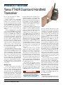
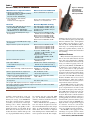
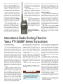
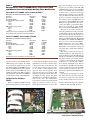
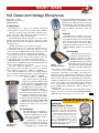
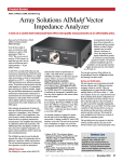
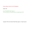
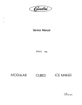
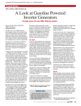
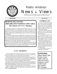
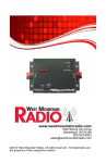
Product Review and Short Takes from QST Magazine
February, 2005
Product Reviews:
Yaesu FT-60R Dual-band Handheld Transceiver
International Radio Roofing Filters for Yaesu FT-1000MP Series Transceivers
West Mountain Radio PWRgate and Computerized Battery Analyzer
Short Takes:
Heil Classic and Heritage Microphones
Copyright © 2005 by the American Radio Relay League Inc. All rights reserved.
PRODUCT REVIEW
Yaesu FT-60R Dual-band Handheld
Transceiver
Reviewed by Dan Henderson, N1ND
Contest Branch Manager
Ready to replace the old handheld
transceiver with one of the dual-band
models? If so you’ll want to check out
the latest offering from Vertex Standard,
the Yaesu FT-60R. This lightweight (13
ounce) transceiver packs good “bang for
the buck” with many extra features that
will appeal to most Amateur Radio operators.
The Yaesu FT-60R claims a 5 W punch
on the 144 and 430 MHz amateur bands,
though the model tested at ARRL fell a
bit short on 430 MHz. (The ARRL Lab
measurement was 4.3 W on that band
measured both on batteries and with an
external dc supply. Yaesu indicates that
this just requires a simple dealer adjustment and is not typical.) With three nominal power levels (5, 2 and 0.5 W) the
amateur providing communications for a
public service event or emergency response should be able to use this radio
for a normal operating shift and be able
to get the message through.
I find the smaller readouts on some
radios a bit hard to read. I was pleasantly
surprised that the FT-60R provided a clear
and concise display on the radio, and an
easy to read and follow operating manual.
This made programming relatively
simple. As with so many of today’s products, the wide array of programmable
options included with the radio requires
you to refer to the manual for general setup. This manual was very user friendly,
with simple step-by-step instructions for
each process.
Making it Play
Since the whole purpose of a radio is
to use it, I am a firm believer in being
able to get on the air with the product as
easily as possible. The FT-60R did not
disappoint in this area. The ON/OFF/VOLUME knob is the smaller of the two knobs
on top of the radio. Once a charged battery back is attached to the rig and an
antenna is attached, you simply turn the
knob clockwise and you are set to receive.
The larger knob on the top allows you to
adjust the frequency up and down. The
squelch adjustment is a ring knob at the
bottom of the larger knob. I found this to
be preferable to several comparable radios that have the squelch adjustment as
a digital control, making it necessary to
program in the squelch level.
Now that the radio is on, there are several ways to select a frequency. For the
beginner, you may simply use the keypad on the front panel and punch in the
desired frequency. If your choice is a
common repeater output frequency, say
145.45 MHz simply key in 145450 and
the FT-60R will automatically select the
appropriate repeater offset for the frequency selected. The same is true for
standard repeater splits on the 430 MHz
band. Don’t fret—the FT-60R will also
automatically set itself to simplex when
a standard simplex frequency is selected.
Once the frequency is selected (and unless there is tone access required for your
selected repeater), you are ready to get
on the air.
After the initial set-up you will
quickly learn that the F/W key, which is
key D—the very last key on the keypad,
will allow access to the secondary functions for the rest of the keypad. Once the
secondary function is selected, the large
knob on the top (used to change the frequency in its primary mode) allows you
to select the desired variable for the selected secondary function. Remembering
this combination makes programming the
secondary functions easy.
For example, if you wish to operate
the radio on a 146.91 MHz repeater that
uses a 91.5 Hz CTCSS tone—first key in
the frequency. The radio will go to that
frequency and show the standard offset
(–600 kHz). Now, to set the access tone,
Joel R. Hallas, W1ZR
From February 2005 QST © ARRL
Bo
tt
om Line
Bott
ttom
This new dual-band handheld
transceiver offers a lot in a rugged,
compact, easy to use package.
Assistant Technical Editor
press the F/W key, then press the 1 button (indicating that you are selecting the
continuous tone-controlled squelch system (CTCSS) or digitally coded squelch
(DCS) function). The main display will
change to show which type is currently
in memory or OFF , as the case may be.
Simply turn the large knob on top until
the display shows TONE, the press the
F/W button again, and you will have
turned on the CTCSS function. Now to
choose the proper CTCSS tone, press the
F/W button again, then press the 2 button. You can then turn the selection knob
on top until you find the proper CTCSS
tone. A final push of the F/W button once
the display reads 91.5 and the FT-60R
will be ready transmit the CTCSS tone
of 91.5 when transmitting on the frequency selected. It sounds more complicated than it is, but with the well written
operating manual as your guide you will
quickly be able to use the wide variety of
features provided.
Once you begin using any handheld
transceiver the variety of extra features—
the bells and whistles—distinguish one
model from its competition. The FT-60R
offers an attractive package of extras that
will appeal to a wide range of interests.
I especially enjoyed the broad coverage
receiver capability of the radio. It is
capable of receiving the 108-137 MHz
aircraft band, both in AM and FM. It then
continues its coverage to 137 to 520 MHz,
and 700 to 999.990 MHz, FM only, less
the cellular frequencies.
Memories to Burn
Your desired receiving frequencies can
readily be programmed into the large
[email protected]
Table 1
Yaesu FT-60R, Serial Number 4K050350
Manufacturer’s Specifications
Measured in the ARRL Lab
Frequency coverage: Receive,
108-137 MHz (AM), 137-520 MHz (AM/FM),
700-999 MHz (cell blocked);
transmit, 144-148, 430-450 MHz.
Receive and transmit, as specified.
Power requirements: 6.0-16.0 V dc1;
receive, 0.13 A;
transmit, 1.6 A max, high power.
Receive, 0.17 A (max volume, no signal);
Transmit, 1.7 A. Tested at 7.2 V.
Receiver
Receiver Dynamic Testing
Sensitivity: AM, 10 dB S/N, 108-137; 0.8 µV;
FM, 12 dB SINAD, 140-150 MHz,
0.2 µV; 174-300 MHz, 400-470 MHz,
800-900 MHz, 0.5 µV; 900-999 MHz, 0.8 µV.
AM, 10 dB S+N/N, 120 MHz, 0.56 µV;
FM, 12 dB SINAD, 144 MHz, 0.13 µV;
222 MHz, 0.16 µV; 430 MHz, 0.16 µV;
902 MHz; 0.5 µV.
Two-tone, third-order IMD dynamic range:
Not specified.
20 kHz offset from 146 MHz, 67 dB;*
10 MHz offset from 146 MHz, 85 dB;
20 kHz offset from 222 MHz, 65 dB;*
20 kHz offset from 440 MHz, 58 dB;*
10 MHz offset from 440 MHz, 83 dB;
20 kHz offset from 902 MHz, 55 dB.*
Two-tone, second-order IMD dynamic range:
Not specified.
80 dB.
Adjacent-channel rejection: Not specified.
20 kHz offset from 146 MHz, 67 dB;
20 kHz offset from 222 MHz, 65 dB;
20 kHz offset from 440 MHz, 58 dB;
20 kHz offset from 902 MHz, 55 dB.
Spurious response: Not specified.
IF rejection, 146 MHz, 92 dB;
222 MHz, 115 dB; 440 MHz, 142 dB;
902 MHz, 128 dB.
Image rejection, 146 MHz, 79 dB;
222 MHz, 68 dB; 440 MHz, 68 dB;
902 MHz, 4 dB.
Squelch sensitivity: Not specified.
At threshold, 146 MHz, 0.06 µV;
440 MHz, 0.11 µV.
Audio output: 400 mW
at 10% THD into 8 Ω (7.2 V dc).
720 mW at 10% THD into 8 Ω (battery);
810 mW at 10% THD into 8 Ω (dc1).
Transmitter
Transmitter Dynamic Testing
Power output: 5.0 W high, 2.0 W mid, 0.5 W low. 146 MHz, 5.1 / 2.0 / 0.5 W;
440 MHz, 4.3 / 1.6 / 0.4 W.
Spurious signal and harmonic suppression:
60 dB for high and mid, 40 dB for low.
VHF, 62 dB; UHF, 72 dB.
Meets FCC requirements.
Transmit-receive turnaround time (PTT release
to 50% of full audio output): Not specified.
Squelch on, S9 signal, VHF, 180 ms;
UHF, 170 ms.
Receive-transmit turnaround time (“tx delay”):
Not specified.
VHF, 80 ms; UHF, 77 ms.
Size (height, width, depth): 4.3"×2.3"×1.2", weight: 13.1 ounces.
Note: Unless otherwise noted, all dynamic range measurements are taken at the ARRL
Lab standard spacing of 20 kHz.
*Measurement was noise limited at the value indicated.
1
External dc: battery is 7.2 V.
available channel memory. And you
won’t have to worry about available
memory for storage, as the FT-60R has
more than enough memory channels
to handle your selections. You begin
with up to five “home” channels that
allow you to store and quickly recall a
primary frequency on each band. In addition there are memory slots for the 10
weather broadcast channels and up to 50
sets of programmable memory channels
for scanning. Top the count with 1000
(yes, one thousand) standard memory
channels, and there should be more than
enough for any application.
These channels have the capability to
store not only the frequencies, but also
the various CTCSS or DCS codes, unique
offset, or other information desired to
utilize them. The inclusion of alphanumeric labeling for the channels makes for
easier operation and recall. For example,
Figure 1—Although
it is thicker than
some low-power
units, the FT-60R is
still easy to handle.
if during your travels you use two repeaters on the same frequency pair, but with
different CTCSS codes, with alphanumeric labels you don’t have to guess
which is which. The FT-60R includes a
wide range of scanning functions that
make this expanded memory useful, including priority channel alert and weather
alert scanning.
Additional Features
Many amateurs today want to be available on the radio when friends call, but
don’t wish to be disturbed by communications not intended for their station. By
using an enhanced paging and code
squelch system (EPCS), the FT-60R can
be utilized as a pager. Simply put, you
can set your receiver to only open when
a specific CTCSS tone is received on the
frequency being monitored. This allows
friends to “give you a call” by activating
your radio. The FT-60R automatically
disables the EPCS after it has received
the incoming page, which lets you know
someone tried to contact you if you were
away from the radio at the time.
The FT-60R includes two interesting
emergency features. One allows you to
press a single button for several seconds
to activate an emergency alert on the primary UHF channel. Someone needs to be
monitoring the channel at another
location. This feature could be useful for
families of licensed amateurs to know to
get help quickly. Second is an emergency
automatic ID system that allows you to
locate someone with an FT-60R who
might be down or incapacitated, trapped
in a disaster, or lost in a search-andrescue situation. Both have the potential
to be very useful in specific situations.
The FT-60R is also equipped to take
advantage of a repeater system or home
base that is tied into the Vertex Standard
From February 2005 QST © ARRL
Wide-Coverage Internet Repeater
Enhanced System (WIRES). Also
new to me with this radio was its automatic range transponder system
(ARTS), a system that allows you
and another ARTS-equipped station
to determine if you are within range
for radio communications. Again, I
could see this feature being useful
for groups on an outdoor outing and
the like, but it is one of the bells and
whistles that I would probably not
be inclined to utilize. The FT-60R
has all the required pieces to allow
repeater autopatch use, something
that we have come to expect.
One interesting feature that
some may be inclined to use is the
ability to use a password system to
secure your radio. You may set up
a four digit (numbers and letters are
available) password that would be
required to activate your radio. For
those with curious children around
the house who want to get on the radio
just like their parent, this would be a
good feature to stop unauthorized
transmissions.
The FT-60R offers two userdefinable keys on the front panel. By
following the detailed instructions
in the manual, a user is capable of
adding certain features (such as
specific memory recall) to the basic
operation of the radio simply at the
press of a button.
One last available feature,
which I did not have the
ability to test (optional software and a cable is required),
was programming software.
This option allows you to
use your PC to set up the
Figure 2—The supplied
antenna is much larger than
the radio.
memory channels then import the data
file to the radio, eliminating the need to
punch in the options manually for each
channel. This timesaver could be a real
plus considering the number of memory
locations provided.
And the Verdict Is…
Overall, I found the FT-60R durable
and straightforward to operate. It performed well in on-the-air testing. Comments from other operators praised its
transmit audio quality. I found that it
offered a wide range of features for a
moderately priced radio—this is one that
I would consider adding to my shack,
even though I might not need all the features it offers.
Manufacturer: Vertex Standard, 10900
Walker St, Cypress, CA 90630; tel 714827-7600; www.vxstdusa.com. Price:
FT-60R, $199.99; ADMS1J, programming software, $38.99; CT27, cloning
cable, $11.99.
International Radio Roofing Filters for
Yaesu FT-1000MP Series Transceivers
Joel R. Hallas, W1ZR
Assistant Technical Editor
It is not an exaggeration to say that
today’s top ranked Amateur Radio transceivers have receivers that are far better
in most respects than those of earlier generations. Fortunately for us (perhaps
unfortunately for manufacturers) every
advance in technology results in the raising of the bar for some parameter or other.
In the very early days, there was a quest
to be the most sensitive. The sensitivity
goal was followed by a desire for optimum selectivity. Then came image rejection, linear and consistent tuning rate,
reduction in front-end overload and on
and on it went. Each advance seemed to
highlight the next parameter that needed
attention.
Today a remaining Achilles’ heel of
our highly refined receivers seems to be
near-in third order intermodulation distortion (3OIMD). All mixers have products beyond the usual signal frequency ±
the local oscillator. Generally other products are reduced significantly, but if the
signals are very strong the undesired
products can be heard. A particularly
troublesome response is from the combination of signals at one frequency and
From February 2005 QST © ARRL
twice another frequency, referred to as the
third order (K×f 1×f 22) response. The
3OIMD response of your receiver can
generate an interfering signal(s) right on
top of the one you are listening to from
two (or more) signals outside your listening passband.
This parameter has been discussed a
number of times in the past in QST and
elsewhere.1 This phenomenon manifests
itself while you are trying to copy a weak
signal on frequency f 1, and there are
strong signals at f1 plus a small increment
and another at f1 plus twice the same increment.2
This effect can be verified by switch1 D.
Potter, W2GZD (now W4RPI), “Intermodulation Reviewed,” QST , May 1983,
pp 17-18.
Bo
tt
om Line
Bott
ttom
A transceiver popular with the
contest and DX communities can
be brought up to date at reasonable cost using InRad roofing
filters.
ing in your attenuator, or turning off your
receiver preamp. The 3OIMD response
will be reduced three times as fast as the
desired signal and often the 3OIMD
signal(s) will disappear. Unfortunately,
by reducing the receiver gain, you are also
reducing the desired weak signal. Even
though it is not reduced by as much as is
the 3OIMD response, it may become difficult copy.
Fortunately, many casual operators
don’t notice this effect since there usually aren’t as many really strong signals
all over the band much of the time. The
real problem shows up during contests
when signals may be every 0.5 kHz (for
CW) or every 2 kHz (for SSB contests)
over the whole band. During DX pile-ups,
the same situation may occur. The signals tend to be clustered more tightly, but
the often weak DX station will request
calls up 2 or 5 kHz, setting the stage for
3OIMD just when you’re trying to figure
out which station he’s calling.
It’s worth noting that while we test in
the Lab with two signals for each mea2For
example, if you are trying to listen at
14,020 kHz and there are strong signals at
14,023 and 14,026 kHz.
Table 2
Comparison of Two FT-1000MP Series Transceivers With
and Without International Radio Roofing Filter Modification
Yaesu Mark V FT-1000MP, serial number 0K120017
Data taken on 20 meters with pre-amp off
Parameter
Unmodified
Noise Floor
–123 dBm
Audio/IF Bandwidth
600 Hz
Blocking Dynamic Range, 20 kHz
130 dB
5 kHz
105 dB
2 kHz
102 dB
1 kHz
104 dB1
IMD Dynamic Range, 20 kHz
88 dB
5 kHz
76 dB
2 kHz
69 dB
1 kHz
68 dB
*Measurement was noise limited at the value indicated.
1
Some filter blow-by was noted on this measurement.
Modified
–130 dBm
470 Hz
146 dB*
130 dB*
105 dB
106 dB1
93 dB
89 dB*
79 dB*
69 dB*
Yaesu FT-1000MP, serial number 7J21036
Data taken on 20 meters with pre-amp off
Parameter
Unmodified
Noise Floor
–123 dBm
Audio/IF Bandwidth
600 Hz
Blocking Dynamic Range, 20 kHz
138 dB
5 kHz
111 dB
2 kHz
106 dB
1 kHz
102 dB*
IMD Dynamic Range, 20 kHz
94 dB
5 kHz
76 dB
2 kHz
69 dB
1 kHz
68 dB*
*Measurement was noise limited at the value indicated.
surement point (5 and 10 kHz, for the
5 kHz spacing, for example), in real life
we get a spurious signal from every such
pair. Thus we will get a 3OIMD response
from 5 and 10 kHz off frequency signals,
but also from 3.3 and 6.6 kHz and –4 and
–8 kHz and 2 and 4 and 8 kHz, etc. This is
why we usually don’t just hear 3OIMD as
a single signal—it just sounds like junk.
So What Can We Do About
3OIMD?
The key to fighting 3OIMD is to keep
the interfering signals out of the stage that
Modified
–126 dBm
470 Hz
141 dB
128 dB
108 dB
103 dB
100 dB
90 dB*
71 dB
68 dB*
is generating the problem response. The
optimum way to do this is to filter right
at the antenna. This can be effective, but
is really only feasible if you only operate on a single or small number of frequencies. The most frequently used
approach these days is to design an RF
stage (if needed at all) and first mixer that
can handle the large signals with minimum distortion, and follow immediately
with a roofing filter. The roofing filter
need only be as wide as the widest bandwidth of signals you wish to process
further downstream in the receiver—but
Figure 3—The International Radio roofing filter.
that’s the rub. Many receivers are designed to do everything—CW, SSB, AM
and FM and thus settle on a roofing filter
that is 15 to 20 kHz wide. The problem
is that if you’re a contester you end up
with all those signals ±7.5 to 10 kHz
away. In addition, the filter skirts may not
be steep, so you may get signals even further removed. Note that IMD from signals spaced at 20 and 40 kHz (the 20 kHz
IMD data in QST Product Reviews 3 )
comes out looking good with this filter,
but not so for signals at 5 and 10 kHz
(the recently added 5 kHz IMD reports).
The best of the newest transceivers
solve this problem by having selectable
roofing filters to allow an optimum choice
for each mode. The Ten-Tec Orion is notable in having optional roofing filters as
tight as 0.25 kHz bandwidth. The ICOM
IC-7800 has two (15 kHz and 6 kHz) and
the soon to be released Yaesu FTDX9000 promises three (15, 6 and 3 kHz).
Single conversion receivers, such as the
Elecraft K2, can set both the roofing and
selectivity with a single filter following
the mixer.
The Ten-Tec Orion (main receiver)
and Elecraft K2 are ham band only designs and thus have their first IF and roofing filters in the HF region. The ICOM
and Yaesu transceivers include general
coverage receivers with an upconverting
architecture to a first IF in the VHF region. Narrow bandwidth steep skirted
crystal filters in the HF region are much
easier to make than those for the VHF
region and only recently have filters as
tight as those by International Radio been
available.
Note that the roofing filters are generally wider than the selectivity setting filter (except for single conversion designs
such as the K2). Thus, neither of the in3 M.
Tracy, “ QST Product Reviews—In Depth,
In English,” QST , Aug 2004, pp 32-36.
Figure 4—The roofing filter installed in a Mark V FT-1000MP.
From February 2005 QST © ARRL
terfering signals may be audible at all,
until the second one shows up and the
3OIMD signal appears within the listening bandwidth.
Enter International Radio
International Radio (InRad) has been
providing high quality selectivity setting
filters for years, and has now responded
to the need for roofing filters as well. They
have designed a (almost) plug and play
roofing filter for the Yaesu FT-1000MP
series transceivers with a bandwidth of
4 kHz instead of the stock 12 kHz unit.
The InRad filter has steeper skirts as well.
Note that this bandwidth will start to improve intermod problems resulting from
signals farther apart than a 1 kHz spacing
(+2 in Table 2), and that is what we observed. Note that the downside is that this
receiver will be sharp (barely communications quality) for AM reception and useless for FM. Fortunately, the MP series
radios have a second receiver that can be
used for these modes. Most serious contesters and DXers will be happy to make
that trade.
How The Roofing Filter Sounds
(or Doesn’t Sound) on the Air
Tom Frenaye, K1KI
Director, ARRL New England Division
During the K1KI multioperator-single transmitter effort in the October
CQWW SSB Contest, we used one FT-1000MP without and one Mark V
FT-1000MP with the International Radio roofing filter. They were used on
several bands during the weekend. For the single operator November ARRL
Sweepstakes CW contest an FT-1000MP with the roofing filter was used as
the main radio, and one without the roofing filter was used as a second radio.
In trying to figure out what could be said about the radio’s performance
with the roofing filter, what stands out is what doesn’t happen. In the past
when there were very loud signals (S9+20 dB or so) on the band, we’d often
hear extra IMD products on our frequency, even if the loud signals were 10
to 20 kHz away. With the roofing filter installed, we just don’t hear them at
all, unless they are very close in frequency. Listening to other stations on
CW or SSB is less stressful without the extra noises!
When looking for a clear spot on 40 meter SSB, the radio with the roofing
filter is able to find more “holes” between the S9+40 dB international broadcast stations, and able to copy other stations that would not have been heard
in the past.
After the first Ten-Tec Orions hit the bands in late 2003, there were several times when good friends with new Orions seemed to start up too close
to our frequency. It turned out they couldn’t even hear us. It became clear
that the performance of that radio was superior to the FT-1000MPs used
here. With the International Radio roofing filter, the situation seems to be
back to even again in the never-ending goal to keep up with the competition!
Hooking it Up and Checking it Out
ARRL Lab Engineer Michael Tracy,
KC1SX, has installed and tested a roofing
filter in two versions of the FT-1000MP
series so far—a Mark V FT-1000MP and
an early FT-1000MP. The first of these
versions require that two small wires be
soldered to existing pads on a PC board to
provide pins for attachment. Other versions have the pins already in place and
the filter can drop in. The filter module
includes an amplifier to compensate for
the filter insertion loss. Figure 3 shows a
close-up of the filter board, while Figure
4 shows how it fits under the chassis (top,
center) of the Mark V.
Before and after lab testing for both
radios is shown in Table 2 and the improvement is notable. Note that the filter
also improves a related parameter—
blocking dynamic range. BDR is a measure of how much stronger than the noise
floor an off-frequency signal needs to
be to reduce the gain of the receiver by
1 dB. Generally, this is less of a problem
than 3OIMD, but can still be troublesome
since it only requires a single out of band
signal. A strong CW signal that you can’t
hear can result in the receiver gain going
up and down, for example. While this is
not great, it’s usually not as bad as having a 3OIMD signal right on top of the
one you’re trying to copy.
We have no clear answer for why the
results differ between the two radios
tested. It should be clear that the better
the original filter is, the less improvement
there will be. It is also possible that the
radio with the least improvement (an earlier version) was generating some level
of 3OIMD response in the mixer ahead
of the filter. In any case, the filters resulted in notable improvement in both
cases. The sidebar relates to the radio
with the least difference.
Manufacturer: International Radio,
13620 Tyee Rd, Umpqua, OR 97486;
tel 541-459-5623; fax 541-459-5632;
www.qth.com/inrad/. Price: $165.
West Mountain Radio PWRgate and
Computerized Battery Analyzer
Reviewed by Larry Wolfgang, WR1B
Senior Assistant Technical Editor
A friend recently gave me a 12 V, 100
ampere hour (Ah) gelled electrolyte battery that had been pulled from service in a
bank of emergency power backup batteries. The commercial communications service my friend works for replaces the
entire bank of batteries if one of the batteries drops below about 80% capacity. My
From February 2005 QST © ARRL
main reason for having the battery is to
have a power source to run some radio
equipment so I can demonstrate ham radio
when I go camping with Boy Scout groups.
I needed a convenient way to keep the
battery charged and ready to go for weekend campouts. I contemplated various
additional pieces of equipment that I
might need to safely keep the battery
charged and also be able to connect my
station equipment to exercise the battery
occasionally. I have used a small portable
solar panel and a Micro M + charge controller4 to recharge the battery after sum4
The ARRL Handbook for Radio Communication , 2005 edition, pp 17.41-17.44. Available from the ARRL Bookstore for $39.95
plus shipping. Order number 9280. Telephone toll-free in the US 888-277-5289, or
860-594-0355; www.arrl.org/shop/.
mertime Scout operations—not good for
winter months.
While looking through a recent issue
of QST, I noticed an ad for the West
Mountain Radio PWRgate PG40. The
PWRgate can handle up to 40 A continuously, either from a power supply or battery. That makes it a perfect match for
my 40 A switching supply, and will
handle the current requirements of my
Elecraft K2/100 HF rig, KAT100 antenna
tuner and a VHF FM transceiver and other
station accessories.
The PWRgate PG40 looks like a small
heat sink with three sets of Anderson
Powerpole connectors on top. The Powerpole connectors follow what has become
the common standard for ARES and
other emergency operators. The compact
PG40 package is about 4×5×15/8 inches
(H×W×D), and has mounting holes on
each end. Connect your 13.8 V dc supply
supply to the PS input and your 12 V battery to the BAT input. Then connect your
rig or dc distribution panel to the OUT connector and you are ready to operate.
When the ac supply is on, your station power supply powers your equipment. If the ac supply goes off for any
reason, the PWRgate instantly routes the
battery voltage to the output connector.
My radios didn’t even blink when I tested
the operation by pulling the PS connector out of the PG40. With my K2 display
set to read applied voltage and current I
could see the supply change instantly
from 13.8 to 12.0 and back again when I
unplugged and reconnected the ac supply to the PG40. With a PG40 connecting my ac supply and back-up battery, I
may not even know the commercial power
went off until it gets dark.
your dc wiring design. 5 The PWRgate
also uses a diode and resistor to provide
up to 1 A of charge current to the battery
when the ac supply is operating. When
the ac power comes back on, the PG40
will switch back to your power supply
and your battery will start to recharge at
up to a 1 A rate.
It will take a while to recharge my 100
Ah battery if it is completely discharged.
After a relatively brief operating period
on the battery, though, the PG40 will top
up the battery and keep it fully charged
and ready for the next emergency or
weekend campout.
a PC running Windows 98SE or higher
with a Pentium 233 or faster processor, at
least an 800×600 display and an available USB port.
The warnings about heat build-up
when charging and discharging the batteries point to the value of the optional
temperature probe. This optional device
plugs into the side of the CBA. When
connected, the software will display the
temperature. You can set an automatic test
cut-off temperature, so if your battery
becomes too hot the test will stop. The
default temperature is 140°F, but you can
change that in the software.
How Do You Know That Battery is
Taking a Full Charge?
Setting Up a Test
As any battery ages it will tend to lose
some of its ability to take a charge and
return the energy as useable current. This
is where the West Mountain Radio Computerized Battery Analyzer (CBA) becomes valuable. The CBA looks like a
large heat sink and top-mounted fan attached to a small plastic tray. It measures
about 23/4×3 1/2×3 inches (H×W×D). See
Figure 5.
An 8051 microcontroller measures
current, temperature and voltage, in three
automatically switched ranges to 10 bit
resolution. The microcontroller operates
a pulsewidth modulated power MOSFET
load for the battery under test. A plugand-play USB interface to your computer
allows software control of the load current, temperature sensed cut-off (with the
optional temperature probe) and also allows the computer to collect data about
the battery discharge characteristics.
The user interface to the CBA is via
Windows software that installs from a CD
included with the package. You will need
5
J. Hallas, “Emergency Power at W1ZR,” QST,
Dec 2003, pp 41-44.
Before you are ready to start a battery
test, take a few minutes to read the safety
information file on the CD, as well as the
CBA owner’s manual and the battery information and FAQ files. Then double
click on the software icon and a test window will open. Type a descriptive name
into the TEST NAME box. Next you will
have to select the battery type from a dropdown list that includes most battery types.
Enter the battery capacity for the battery
you are testing. When you connect the
battery to the CBA it will measure the battery voltage and take a guess at the nominal battery voltage and the number of cells
in the pack. The software usually defaults
to a test current equal to the capacity of
the battery. The software also sets a default test ending voltage; in the case of the
12 V gel cell, the default is 11.4 V.
If you want to use these software defaults, simply click the START button. If
you want to find out how long the battery will run your equipment, set the test
end voltage to the lowest battery voltage
at which your radio will still operate
(taking into account all voltage drops between the battery and radio) and the current to correspond to the drain of your
What’s Inside?
The PWRgate uses two 80 A Schottky
diodes wired to isolate the battery and
power supply from each other. The input
with the higher voltage automatically
connects to the output. The Schottky diodes have a forward voltage drop of about
0.4 V that should be considered during
Figure 5—The Computerized Battery Analyzer consists of a heat sink and small fan
sitting on top of a plastic tray.
From February 2005 QST © ARRL
Figure 6—The results of testing my pulled 100 Ah gel cell.
I set this test to draw 7 A from the battery. Notice that the test
stopped when the battery voltage dropped to 10.4 V. This
battery appears to have a capacity of about 88 Ah, rather
than the rated 100 Ah.
setup. The graph automatically adjusts
the vertical voltage scale and the horizontal capacity scale to suit your test. The
CBA continues to draw the specified current until the battery voltage drops to the
end voltage.
The CBA can dissipate at least 100 W,
higher for lower capacity battery packs.
If you try to set a test current that will
exceed the ratings, the software will
prompt you to reduce the test current to
a safe level.
I wanted to know how my 100 Ah gel
cell would compare to that rated capacity,
so I ran a test on the fully charged battery.
See Figure 6. With a 7 A load it has a capacity of about 88 Ah, down to 10.4 V.
I also tested a 17.2 Ah 12 V gel cell
that I have used to operate a 2 meter rig
for many of my Scout demonstrations
over the years. I recharged and tested this
battery several times, but it only seems
to have a capacity of about 1.2 Ah. I was
convinced this battery was better than
that, but after several tests I have concluded that it isn’t providing as much
operating time as it should. It may be
well past time to replace that battery. I
also tested another old gel cell that didn’t
seem to be holding a charge very well.
Sure enough, the CBA indicates that battery is beyond any useful life.
To test some known good batteries I
decided to set up test fixtures for a few
other battery types.
A quick trip to RadioShack produced
a single AA cell holder that I clipped to
the Powerpole adapter cable to test some
AA cells. I have been using some NiCd
and NiMH cells for a variety of applications recently, and was curious as to how
From February 2005 QST © ARRL
Figure 7—The results from three battery tests overlaid on top
of each other. The test compares a Sears DieHard alkaline AA
cell with two different NiMH AA cells.
they tested when compared to an alkaline cell [note that testing the capacity
of a non-rechargable battery is a destructive test, but useful on a sample of a battery type—Ed.]. Figure 7 shows a graph
comparing three different AA cells.
Other Software Features
The CBA software has a number of
other very useful features. Obviously,
you can save each test graph for later
review. You can also overlay one test on
top of another. Figure 7 shows three such
graphs overlaid on each other. When you
overlay a test graph, the software color
codes each new graph, and also places a
color-coded legend along the right side
of the graph. If you have a color printer,
you can print the image in color. If you
only have a black printer, then the software will add symbols to the lines and
legend to distinguish them from each
other.
The software also has a print labels
feature that helps you set up and print
labels to apply to your batteries. If you
have several similar packs, this is especially useful because it helps you keep
track of the individual packs. Rather
than always using the same one or two
packs, you can easily rotate the several
packs and use them uniformly. You can
also keep track of which packs are older,
so it is easier to decide when to test a
pack that may be getting past its useful
life. The label template is set up to use
Avery 05160 or equivalent label sheets.
How Often Should I Test My
Batteries?
That is an important question. If a re-
chargeable battery is good for a certain
number of charge/discharge cycles, then
every time you test the battery you can
subtract one from the remaining life of
your battery. Obviously, over testing is
not a good thing. West Mountain Radio
suggests that you run a test for a new
battery pack [especially good advice for
NiCd batteries—Ed.]. That will give you
a point of comparison as the pack ages.
They also recommend that you retest the
pack after it has been setting for some
time, or after it has been used a great
deal. I would probably err on the side of
not testing often enough rather than over
testing. West Mountain Radio says they
do not recommend testing or cycling batteries if they are used regularly and seem
to be working well. That makes sense to
me.
Testing Accuracy
I used my digital multimeter (DMM)
as an ammeter to verify that the actual
load current was close to the indicated
test current. Within the accuracy of my
meter, I measured the same current as
the CBA. I also used the DMM to monitor the battery voltage during a couple
of tests. Again, within the measurement
accuracy of my meter, the CBA software
was reporting the same terminal voltage.
The manufacturer reports that by our
publication date they will offer a CBA II
with higher resolution at low current.
Manufacturer: West Mountain Radio,
www.westmountainradio.com, 18
Sheehan Ave, Norwalk, CT 06854; tel 203853-8080. Price: PWRgate PG40, $69.95;
Computerized Battery Analyzer, $99.95;
Temperature Probe for CBA, $10.95.
SHORT TAKES
Heil Classic and Heritage Microphones
Mike Gruber, W1MG
ARRL Laboratory Engineer
[email protected]
The Heil Classic
The Heil Classic is a replica of a 1930 RCA 74B broadcast microphone. A few of its more notable features include:
• Two mic elements easily selected by a miniature backpanel toggle switch. The elements are partially selectable at
the time of purchase. More about this later.
• Switchable high and low im1pedance is set by a tiny
bottom-panel slide switch. The Classic is therefore compatible with both vintage tube transmitters and modern solidstate transceivers.
• A PTT “Soft Touch” switch on the back panel.
Perhaps the Classic’s most prominent visual feature is its
cast aluminum name flag. Complete the warranty card that
comes in each box and Heil sends you the call letters of your
choice. The letters are plastic with an adhesive backing.
Four possible elements come with Heil Classic microphones.
One is standard issue for all mics. The customer selects the
second element from one of the three remaining options:
PRO LINE: This is a broadcast element with a frequency
response of 50 to 18,000 Hz. It is the standard element in all
versions of the Heil Classic microphone.
HC-4: The “DX Dream Machine” is a dynamic element
engineered for contest and DX operators. It has a specified
500 to 3800 Hz response with a 10 dB rise at 2000 Hz.
HC-5: The “Key Element” is a dynamic cartridge designed
for general SSB communication. It has a specified frequency
response of 350 to 4000 Hz with a 6 dB rise at 2000 Hz.
Heil IC: This is a “high performance electret element” specifically
designed to provide the higher audio
levels required for older ICOM radios.
It’s specified at 35 to 10,000 Hz at –3 dB.
The Heil Classic microphone comes
in three different versions as follows:
Classic 5—Includes the PRO LINE
broadcast element and the HC-5. This is
the version we obtained for this review.
Classic 4—Includes the PRO LINE
broadcast element and the HC-4 element.
Classic IC—Includes the PRO LINE
broadcast element and IC element. As
mentioned previously, this is for older
ICOMs only.
The Heil Heritage
The Heil Classic
microphone.
The Heil Heritage microphone is
styled after the Shure 55. Right from
the box, its sparkling heavy chrome
finish was an attention grabber
here at Headquarters.
The Heritage is a single element
dynamic microphone. Its frequency
response is specified to be smooth 40
to 18,000 Hz with a standard bal-
anced output of 600 Ω. The Heritage has a mute
switch, but not a PTT switch. PTT is accomplished via an outboard switch connected to
the Heil interface cable. The Heritage also has
a 5/8-27 standard thread assembly that mates
with all of Heil’s microphone stands and
booms.
On the Air
Both the Classic and Heritage mics were
used on the air with a variety of operators,
rigs and modes. In all cases we tried, the Heil
mics received excellent audio reports. These
mics were also the clear favorite in blind
comparisons with the stock mic that came
with my ICOM IC-746 transceiver and other
radios.
Final Thoughts
Although the Classic does have
a PTT switch, I didn’t find it convenient for general use or longwinded transmissions. I’d suggest
an additional hand or foot operated
PTT switch, both of which are availThe Heil
able
from Heil. (Obviously, the HeriHeritage microphone.
tage requires an outboard PTT switch
since it only has a mute switch.)
There are a few caveats when selecting a mic or its associated hardware. The Classic, for example, comes with a base;
the Heritage does not. If planning on a Heritage, you’ll probably want to buy the CB-1 base stand, especially of you don’t
plan on a boom. (The base is surprisingly heavy and features
a rubber non-skid bottom.) It’s also particularly important to
get the correct cable for your radio and microphone. The Classic is a four-pin XLR connector while the Heritage is only a
three-pin XLR. Classic and Heritage cables are therefore not
interchangeable.
Manufacturer: Heil Sound Ltd, 5800 North Illinois, Fairview
Heights, IL 62208; tel 618-257-3000; www.heilsound.com.
MSRP: Heritage $130; Classic (all versions) $229.
New Products
OHM’S LAW
DESK AND WALL CLOCKS
TechNote Time Watch Company has
added Ohm’s Law desk and wall clocks
to their line of Ohm’s Law wristwatches.
TechNote Time Watch Company now
carries 12 different products for both ac
and dc applications. For more information, see www.technotetime or contact
TechNote Time Watch Co, 5330 SE 28th
Ln, Ocala, FL 34471; tel 352-694-2744
or [email protected].
From February 2005 QST © ARRL