1
Command
Console
SL
REGULATORY
FCC INFORMATION
WARNING
TO PREVENT FIRE OR SHOCK HAZARDS, DO NOT EXPOSE THIS UNIT TO RAIN OR
MOISTURE. ALSO, DO NOT USE THIS UNIT’S POLARIZED AS PLUG WITH AN EXTENSION
CORD RECEPTACLE OR OTHER OUTLETS UNLESS ALL THREE PRONGS CAN BE FULLY
INSERTED
2. Changes or
modifications not
expressly approved by
Z Microsystems could
void user’s warranty.
1. Use the power and
video cables supplied
with the product to
help prevent interference with radio and
television reception.
The use of cables
and adapters may
cause interference
with electronic equipment in the vicinity of
this unit.
Command
Console
SL
CAUTION
RISK OF ELECTRIC SHOCK - DO NOT OPEN
CAUTION: TO REDUCE THE RISK OF ELECTRIC SHOCK DO NOT REMOVE COVER (OR
BACK OF UNIT). NO USER SERVICEABLE PARTS INSIDE. REFER SERVICING TO QUALIFIED PERSONNEL.
This symbol warns the user that insulated voltage within the unit may have sufficient
magnitude to cause electric shock. Therefore, it is dangerous to make any kind of
contact with any part inside this unit.
This symbol alerts the user that important literature concerning the operation and
maintenance of this unit has been included. Therefore it should be read carefully in
order to avoid any problems.
2
Doc# 27-0032UM Rev A Issued 07/05
TABLE OF CONTENTS
SECTION
PAGE
Introduction ........................................................................................................................4
About This Manual ....................................................................................................4
Safety Precautions....................................................................................................4
Product Description ..................................................................................................5
Installation Instructions .......................................................................................................6
Shipment Contents ...................................................................................................6
Required Tool ............................................................................................................6
Preparations ..............................................................................................................6
Hardware Installation ................................................................................................7
Install Rails ................................................................................................................8
Install Console ........................................................................................................10
ZLocks Description .................................................................................................12
Setup Console ........................................................................................................13
Close Console.........................................................................................................15
Cable Connections .................................................................................................16
Operations.......................................................................................................................16
Power Up ................................................................................................................16
Display Panel Controls ........................................................................................... 17
Display Panel Setup ................................................................................................18
Onscreen Menus.....................................................................................................19
SoftMenus ...............................................................................................................23
Maintenance ...................................................................................................................28
Troubleshooting ..............................................................................................................29
No Main Display Image ...........................................................................................29
Display Image Has Vertical Bars ............................................................................30
Display Image Appears Fuzzy ................................................................................30
Power Light Does Not Illuminate ............................................................................30
Schematics .....................................................................................................................31
Replacements .................................................................................................................36
Appendix .........................................................................................................................37
Specifications for Command Console ...................................................................37
Warranties ..............................................................................................................39
Customer Support ...................................................................................................45
Customer Feedback................................................................................................46
Command Console Serial Control ICD ..................................................................47
3
Doc# 27-0032UM Rev A Issued 07/05
INTRODUCTION
ABOUT MANUAL
This Manual is also available on the Z Microsystems website (www.zmicro.com). We
recommend you read this manual carefully and follow the instructions in the Installation
chapter for verification of system functions and control settings.
Safety Precautions
DANGER:
To avoid shock hazard:
• Do not remove the covers around the
Command Console
• Do not connect or disconnect the
Command Console during an
electrical storm.
• The power cord plug must be connected
to a properly wired and grounded
power outlet.
• Any equipment to which the
Command Console will be attached
must also be connected to properly
wired and grounded power outlets.
4
Doc# 27-0032UM Rev A Issued 07/05
INTRODUCTION
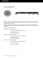
PRODUCT DESCRIPTION
The ultra-slim Command Console SL model is designed for rapid deployable applications
and fits any 19” RETMA rack or transit case. The Command Console SL model brings
together a 19” (1280 x 1024) flat panel display, a full size water tight keyboard and track
ball all in only 1.75” (1U) height.
The Command Console SL model also solved cable retracting problems. An integral
custom engineered articulating arm provides smooth cable management which eliminates
cables from getting tangled and caught on other equipment as the Console is pulled in
and out of the rack.
To further assure rapid deployment, dual quick-lock/release mechanisms hold the Command Console SL model firmly in the storage position and allow it to be quickly set up
and operational. A custom torque adjustable hinge can be adjusted to hold the display
securely at any viewing angle, in the most turbulent situations.
The Command Console SL model is manufactured entirely from lightweight, aircraft
grade, CNC machined aluminum and finished with a tough, baked powder coating to
provide the utmost strength, durability and light weight.
All configurations have the following “key features”:
• USB Connections or PS/2 Connections (connector clamp-down) for keyboard and TB.
• 88-key water tight keyboard.
• Three button sealed trackball
• 12-function keys and arrow keys.
• Fits 24in and 25in deep racks.
5
Doc# 27-0032UM Rev A Issued 07/05
INSTALLATION
SHIPMENT CONTENTS
Ensure all of the following parts are included in the package received from Z Microsystems. Verify all parts have not been
damaged during shipment. If any of the
parts are missing or damaged, immediately
contact Z Microsystems Customer Service
at 858-657-1000.
• Command Console unit
attached to the mounting
plate
• Power Cable
• User Manual
• Video Cable
• Serial Cable
Required Tools
• Rack-mounting hardware
• Phillips screwdriver, 2 pt.
• 5/16 wrench
Remember to save the unit’s original
shipping materials. It may be necessary to
move the unit at a later date.
Preparations
In preparation to install the Command
Console, take the following precautionary
steps:
Verify the Command Console power
switch is OFF.
Do not connect or disconnect the unit during an electrical storm.
The power cord plug must be connected to
a properly grounded power outlet.
NOTE: For the fastest and easiest
installation of the Command
Console, follow these steps
in the sequence they are
presented.
Any equipment to which the unit will be attached must also be connected to properly
wired and grounded power outlets.
6
Doc# 27-0032UM Rev A Issued 07/05
INSTALLATION
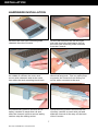
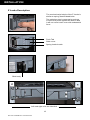
HARDWARE INSTALLATION
Remove the outer rack mounting slide
channels from the Console.
On the rear unscrew the left and right
rear rack mounting brackets to free up
the outer rack mounting slide channels
from the Console.
Press the spring loaded Z Locks towards
the middle to release the outer rack
mount slide channels and at the same
time slide the rack mounting block back.
Slide the channels back until they stop
about half way back. This is a safety stop
to prevent the Console from sliding out
too far while mounted to the rack.
Simultaneously press in the first set of
safety catches on each slide rail and
slide the channel until the second safety
catches stop the sliding action.
Simultaneously press in the second set
of safety catches on each slide rail and
slide the channel all the way off the back
of the Console.
7
Doc# 27-0032UM Rev A Issued 07/05
INSTALLATION
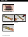
Install Rails
Both outer rack mount slide channels
should be separated at this time.
The slide channels come pre-assembled
to fit a 24” deep rack. To fit a 25” rack, the
rear mounting bracket can be repositioned
as shown here.
8
Doc# 27-0032UM Rev A Issued 07/05
INSTALLATION
To mount the channels on the front of the
RETMA rails (in most cases), use two 1032 Phillips screws...
on each side to secure the Z-Lock mounts.
Be sure to press the slide rail flat against
the RETMA rail as you tighten the screws.
On the rear of the cabinet frame, also use
two Phillips screws on each rail to secure.
On the slide rails, using a screwdriver and
wrench, tighten the slide extension rail
screw. Repeat on each side.
9
Doc# 27-0032UM Rev A Issued 07/05
INSTALLATION
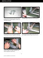
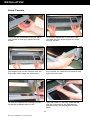
Install Console
Pull the two Console inner members of the
slides out until they lock in the second lock
position.
Hold the Console with the front toward you
and as horizontal as possible. NOTE: In
the next step, be sure to carefully support
and guide the power supply at the rear of
the Console.
Guide the Console’s inner slide member
into the middle slide member, and gently
slide the Console into the slide assembly
until it stops. This may require a second
person to support the power supply.
Press in the first set of catches on each
slide and slide the channel until the second
safety catches stop the sliding action.
Simultaneously press in the second set of
safety catches on each slide rail and slide
the channel all the way off the back of the
Console.
From the back of the rack, gently guide the
power supply toward you.
10
Doc# 27-0032UM Rev A Issued 07/05
INSTALLATION
Secure the power supply to the right rear of
the Console, using #8-32 x .75”L screws.
Secure the left side also, as shown above.
11
Doc# 27-0032UM Rev A Issued 07/05
INSTALLATION
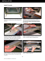
Z Locks Description
The mechanical principle of the Z Locks is
similar to spring-loaded dead bolts.
Two stainless steel compression springs
in each lock press against the bolt so that
it will not come loose even with substantial
force.
Push Tab
Slide cover
Spring loaded catch
Slide body
Left and right units are identical
12
Doc# 27-0032UM Rev A Issued 07/05
INSTALLATION
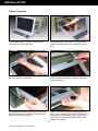
Setup Console
To pull out the Command Console, place
your hands so that your palms face upwards.
Your thumb should be on the tab of the
lock and the first three fingers are under
the pull-out bar.
Push the tabs towards each other and with
your fingers pull out the Console until the
first safety catch stops the slide action.
Press both slide catches inward and pull
the Console out. Allow the Console to stop
at the second catch.
To raise the display into viewing position,
locate the lockdown latch on the...
right top corner of the tray. Slide the tab
with the right hand to the right and lift
simultaneously the display with the left
hand...
13
Doc# 27-0032UM Rev A Issued 07/05
INSTALLATION
...into viewing position.
Push unit into the first locking position of
the slides.
14
Doc# 27-0032UM Rev A Issued 07/05
INSTALLATION
Close Console
To fold down the Console, pull out the
Console fully from the rack
Stand slightly to the right of the unit and
lower the panel down on its back into the
tray.
With the right hand pull back on the tab of
the lock down mechanism.
Lay the panel fully down and release so
that the panel becomes locked in the horizontal position.
Disengage the slide lock from the second
slide lock position. Push the Console into
the first slide lock position.
With a Thumb on the left and right tab of
the Z Lock, slide the Console into the rack
and press on the tabs to open the locks.
Push into maximum seated position and
release the locks.
15
Doc# 27-0032UM Rev A Issued 07/05
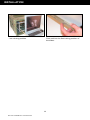
OPERATIONS
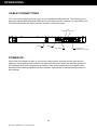
CABLE CONNECTIONS
The connections panel may vary due to non-standard configurations. The following configuration shows both PS2 and USB cable connections on one sample. In most cases, the
Command Console will utilize just one of these connector types.
PS2
KEYBOARD TRACKBALL
POWER
VIDEO
HOST SERIAL
USB (TYPE B)
KEYBOARD , TRACKBALL
POWER UP
When the Command Console is connected, apply power and ensure the main screen
appears. If the display does not turn on within ten seconds, press the Standby button on
the display panel upon completion of cabling. If the main screen does not appear after
hardware and cabling installations are complete, consult the Troubleshooting section of
this manual.
16
Doc# 27-0032UM Rev A Issued 07/05
OPERATIONS
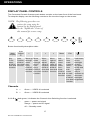
DISPLAY PANEL CONTROLS
The Command Console features push-button controls on the lower front of the front bezel.
To setup the display, use the following controls to fine tune the image on the screen:
NOTE: The following procedures are
written for setup using the
buttons on the display panel.
See the “SoftMenus” section of
this manual for remote setup.
Button functionality description table:
Auto
Position;
KVM offers dual
function
>
Key
Functions;
KVM offers dual
function
<
Auto
Adjust
“Z”
Main
Display
<
Move up
through
menu
functions;
KVM offers dual
function
Move
down
through
menu
functions;
KVM offers dual
function
Move
left to
adjust
value of
function;
KVM offers dual
function
>
Menu
Exit
Move
right to
adjust
value of
function;
KVM offers dual
function
Activates
menu
and
menu
functions;
KVM offers dual
function
Exit
from
main
menu or
return
from
submenu
to main
menu;
KVM offers dual
function
Hold down
to turn
backlight
on and
off; press
briefly and
repeatedly to
increase or
decrease
backlight
brightness
Channels
A —
Green — VIDEO A is selected
B —
Green — VIDEO B is selected
If A & B are both green, it indicates the Channel Auto Switching function is selected.
—
green — power and signal
orange — power and no signal
off — Standby mode
17
Doc# 27-0032UM Rev A Issued 07/05
OPERATIONS
DISPLAY PANEL SETUP
This following section explains how to use the control buttons to adjust image clarity and
image position on the screen. In particular it discusses:
• The function of each of the push-button controls
• How to reset previously saved settings or return to factory settings
• Tips and techniques
NOTE: The control buttons allow
the user to control backlight
operations; to store settings,
and to revert to factory-saved
settings.
18
Doc# 27-0032UM Rev A Issued 07/05
OPERATIONS
ONSCREEN MENUS
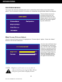
To access the onscreen display main menu, press the menu button on the front of the
panel. The Command Console’s functions are controlled using the Main Menu’s subtopics.
These submenus can be
accessed using the Up
and Down buttons on the
display panel. See sections
below for specifics regarding the submenus.
Main Screen Picture Adjust
Use the Up and Down buttons to highlight the “Picture Adjust” option. Press the “Menu”
button to access the submenu.
��
��
NOTE: Brightness of the main screen can also be
adjusted without entering the Main Menu
using the up and down display buttons.
19
Doc# 27-0032UM Rev A Issued 07/05
Use the Up and Down Keys
to highlight the desired option. Use the Left and Right
buttons to increase and decrease the Brightness and
Contrast characteristics of
the screen. Press “Exit” to
return to the Main Menu.
The new adjustments will
be applied automatically.
OPERATIONS
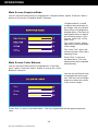
Main Screen Graphics Mode
Use the Up and Down buttons to highlight the “Graphics Mode” option. Press the “Menu”
button to access the “Graphics Mode” submenu.
“Graphics Mode” is used
to adjust the positioning of
the image. Use the Up and
Down Keys to highlight the
desired option. Use the Left
and Right buttons to adjust
the following modes: Horz
Coarse, Horz Fine, H Pos,
and V Pos.
The “Horz Coarse” option
adjusts the horizontal width
of the image.
The “Horz Fine” option adjusts the phase of the video
sampling clock.
Press “Exit” to return to
the Main Menu. The new
adjustments will be applied
automatically.
Main Screen Color Balance
Use the Up and Down buttons to highlight the “Color Balance” option. Press the “Menu” button to access the “Color
Balance” submenu.
Use the Up and Down Keys
to highlight the desired option. Use the Left and Right
buttons to adjust the colors
of the screen image.
Red
Green
Blue
Press “Exit” to return to the Main Menu. The new adjustments will be applied automatically.
20
Doc# 27-0032UM Rev A Issued 07/05
OPERATIONS
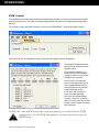
Main Screen Information
Use the Up and Down buttons to highlight the “Information” option. Press the “Menu” button to access the “Information” submenu.
Within this submenu, view
the video mode resolution,
the refresh rate, and the
sync mode. Press “Exit” to
return to the Main Menu.
The Firmware Version and
Build Date are also available on this screen.
�
Menu Timeout:
Main Screen Configuration
�������������
������������
��
����������������������
The menu timeout is the
amount of time the menu
will appear while not in use
before it times out. When
the menu times out, it
disappears from the main
screen. Select with Up and
Down keys and adjust with
the Left and Right keys.
Reset Default Settings:
���������������������
Resets all Main Menu settings to the factory default
settings. Select and press
the Menu button.
���������������
Channel Select Auto:
The Command Console has two channel options. Highlight
“Channel Select” and use the Left and Right keys to
change channels. If both channels have been configured
for use, the following options are relevant:
AUTO: Automatically selects the available channel.
CHANNEL A: Allows the operator to choose Channel A as
active.
CHANNEL B: Allows the operator to choose Channel B as
active (channel B is optional--not standard).
21
Doc# 27-0032UM Rev A Issued 07/05
The Channel LEDs on the
front panel display buttons
reveal the active channels,
as well. See the section
regarding “Controls” for
more details on the channel
LEDs.
OPERATIONS
KVM Control (see KVM on screen on previous page):
Toggles ON/OFF to apply or remove preset KVM command features. The preset commands are programmed
as alternate functions of the firmware buttons on the front
of the panel. For predefining the KVM character strains,
please refer to SoftMenu instructions regarding KVM
Control.
22
Doc# 27-0032UM Rev A Issued 07/05
NOTE: When the KVM
Control is
turned ON,
the Main
Menu requires
the button be
held down for
extended length
of time to be
made active.
OPERATIONS
SOFTMENUS™
SoftMenus™ are control panel dialog screens accessed from the host computer, allowing
flexibility where positioning and environmental demands are a concern.
In order to access the SoftMenu™ features, the host serial port must be accessed at the
rear of the Command Console. The Command Console must be connected to the computer and software must be installed.
The following initializing screen will appear as the SoftMenu™ software is launched:
Clicking on the “Exit” button will cancel the SoftMenu™ program from opening.
23
Doc# 27-0032UM Rev A Issued 07/05
OPERATIONS
Monitor SoftMenus™
The Monitor SoftMenu™ dialog screen allows the operator to adjust Channel Configuration activity, Default settings, Auto Adjust, Brightness and Contrast characteristics,
Coarse and Positioning range, and Color Balancing of the main screen image in one
easy-to-use menu.
Monitor Screen “Factory Default” and “Auto Adjust” Buttons
To adjust the monitor screen settings, the “Monitor” tab must be active.
By clicking on the “Factory Default” button, all settings will automatically reset to the
prescribed factory default values. The “Auto Adjust” feature automatically adjusts the RGB
image to fit the screen.
24
Doc# 27-0032UM Rev A Issued 07/05
OPERATIONS
MENU BAR
The SoftMenus’ menu bar also includes the “Edit” and “Tools” drop-down menus. Left
click on any of the following drop-down menus:
File
Load previously saved display settings and save settings in the “File” drop-down menu.
Multiple users may wish to alter the settings individually with this feature.
Edit
Manage, add, and remove the ports used by SoftMenus for communication with the “Edit”
drop-down menu.
25
Doc# 27-0032UM Rev A Issued 07/05
OPERATIONS
Tools
Tools are available to further enhance the SoftMenus. KVM Setup can be controlled from
this location. See the next page for details on the KVM Control option.
Help
Utilize the software “Help” settings to read about the version of the unit, as well as information about Z Microsystems.
HOT KEYS
Hot Keys are only available on the Linux and Windows versions of Z Microsystems’ software. The following combinations of “hot” keys have been customized for ease of use of
the Command Console.
Ctrl + B
Press the “Control” and the “B” keys simultaneously to turn up the main image’s brightness in small increments.
Ctrl + I
Press the “Control” and “I” keys simultaneously to toggle between all available channels.
NOTE: The panel will only allow a
channel with active input to be
selected.
26
Doc# 27-0032UM Rev A Issued 07/05
OPERATIONS
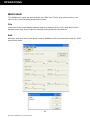
KVM Control
The SoftMenus KVM Control feature enables the display to communicate with the KVM
over the serial port. The ASCII string assignments can only be configured through SoftMenus.
To assign or alter the ASCII strings, click on the SoftMenus’ Tools drop-down menu.
Left click on the “KVM Setup” option and the following screen will appear:
The button images map to
the physical buttons on the
display panel.
Click on the buttons corresponding to the desired
string to gain access to the
assignment screens.
Click on the “Properties”
button to specify the serial
port configuration the display should use to communicate with the KVM.
Click the “OK” button to
save the settings and
exit from the KVM Setup
screen. Click the “Cancel”
button to exit from the KVM
Setup screen without saving
the changes.
NOTE: The exact ASCII strings and serial port properties are defined by the KVM
manufacturer. See the KVM manufacturer’s documentation to assign the
ASCII string.
27
Doc# 27-0032UM Rev A Issued 07/05
MAINTENANCE
MAINTAINING THE COMMAND CONSOLE
WARNING: Be sure to turn off the
power before you perform any
maintenance on the monitor.
WARNING: To avoid risk of electric
shock, do not disassemble the
monitor cabinet. Users cannot
service the monitor. User
maintenance is restricted to
cleaning as explained below.
CLEANING THE COMMAND
CONSOLE
Unplug the Command Console from the
power outlet before cleaning.
• To clean, lightly dampen a soft, clean
cloth with water or mild detergent. If
possible, use a special screen cleaning
tissue or solution suitable for the Command Console.
• Isopropyl alcohol may also be used to
clean fingerprints or smudges on the
face of the monitor. First apply the alcohol to the soft lint-free cloth before wiping the monitor. Do not apply the alcohol
directly on the monitor.
28
Doc# 27-0032UM Rev A Issued 07/05
TROUBLESHOOTING
TROUBLESHOOTING THE COMMAND CONSOLE
No Main Display Image
If there is no image on the main screen, a signal will appear on the screen that states, “No
Input, Check Cable”. If the cable from the computer to the display is secure, determine the
color of the standby LED and follow the appropriate procedure below.
Black
Problem:
If the standby LED is black, there is no
power to the unit.
Recovery:
• Ensure the power cable is plugged
into the source.
• Connect the power cable to a
AC outlet. Ensure the AC outlet is
active.
• Wake up the display by pressing
the standby button.
Orange
Problem:
If the standby LED is orange, there is no
video signal.
Recovery:
• If Video A or Video B is selected,
ensure there is a video signal coming into the selected channel.
• Ensure there is a video signal
coming from the computer.
Green
Problem:
When the standby LED is green, there is
both power and a video signal. If there is
no image on the main display, there is a
possible hardware failure.
Recovery:
• Ensure the video signal coming
from the computer is not a black
screen.
• Contact Z Microsystems’ Customer Support Department.
29
Doc# 27-0032UM Rev A Issued 07/05
TROUBLESHOOTING
Display Image Has Vertical Bars
If the main image begins to display vertical bars, adjust the “Horz Coarse”. From the Main
Menu, use the Up and Down buttons to highlight the “Graphics Mode” option. Press the
“Menu” button to access the “Graphics Mode” submenu. Use the Left and Right buttons
to adjust the screen until the number of bars is reduced. Continue adjusting one step at a
time until the bars are no longer visible.
Display Image Appears Fuzzy
If the main image begins to appear fuzzy or “noisy”, adjust the “Horz Fine” until it is
reduced. The “Horz Fine” option adjusts the phase of the video sampling clock. To access
the “Horz Fine” submenu from the Main Menu, use the Up and Down buttons to highlight
the “Graphics Mode” option. Press the “Menu” button to access the “Graphics Mode”
submenu.
Power Light Does Not Illuminate
1. Check that power cable is properly connected to 110 VAC power supply.
2. Check that front panel power switch is on.
3. Check that power switch on back of Command Console display is on.
30
Doc# 27-0032UM Rev A Issued 07/05
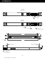
SCHEMATICS
MECHANICAL OUTLINE FOR COMMAND CONSOLE
31
Doc# 27-0032UM Rev A Issued 07/05
32
Doc# 27-0032UM Rev A Issued 07/05
2.561
17.853
5.908
24.000
TO 25.00
14.192
29.317
9.155
17.046
18.806
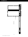
SCHEMATICS
SCHEMATICS
REAR VIEW
PS/2 VERSION
PS/2 TRACKBALL
PS/2 KEYBOARD
REAR VIEW
USB Version
VIDEO
USB (TYPE B)
HOST SERIAL
KEYBOARD , TRACKBALL
.100
.100
18.102
1.250
1.740
.245
18.806
R.100
BACK OF RACK
FRONT OF RACK
3.059
2.258
IEC POWER INPUT
OR
5015 POWER INPUT
33
Doc# 27-0032UM Rev A Issued 07/05
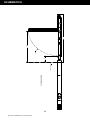
1st Locking Position
FRONT OF RACK
8.09
17.88
14.39
SCHEMATICS
34
Doc# 27-0032UM Rev A Issued 07/05
2nd Locking Position
FRONT OF RACK
3.57
R15.0
17.59
27.38
SCHEMATICS
35
Doc# 27-0032UM Rev A Issued 07/05
REPLACEMENTS
REPLACING PARTS
If the Z Microsystems Technical Support Engineer determines that the product needs to
be replaced, a Customer Service Representative will issue a Return Material Authorization (RMA) number.
An RMA number is required to return a product to Z Microsystems, regardless of the
reason for the return.
The Z Microsystems Customer Service Department/RMA Request Form will ask the customer to provide the following information:
• model number
• serial number
• problem
• return “ship to” address
• the name and address of the company department to which we will send
the invoice (if product is out of warranty or is different from the “ship to”
address.
• phone number and e-mail address of contact
• purchase order number
You will be given an RMA number and will be asked to send the product to:
Z Microsystems
ATTN.: (RMA#) It is very important to reference the RMA#
5945 Pacific Center Dr., Suite 505
San Diego, CA 92121
36
Doc# 27-0032UM Rev A Issued 07/05
APPENDIX
SPECIFICATIONS FOR COMMAND CONSOLE
The Command Console is designed to host a choice of LCD’s from several manufacturers based upon customer requirements. The specifications unique to each particular LCD
vary from manufacturer to manufacturer. These particular specifications are available
through our sales department.
General Display Specifications
Display size
19 Inch
Resolution
Up to 1280 x 1024
Color Palette
16.7 Million
Contrast Ratio
700:1 (typ)
Pixel Pitch
.294 mm x .294 mm
Luminance
300 cd/m2 (typ)
Viewing Angle
80°/80°
Control
Control Panel or SoftMenu
Optical Response Time
15 ms (typ)
Power Consumption
60 W
AC Power Supply
100-240 VAC input@50/60 Hz
Display Cable
6’ cable, HD15
Power Cable
6’ cable, IEC or 6’ cable, 5015
Serial Cable
6’ cable, DB9
Total Package Size
1.74” H x 18.81” W x 29.32” D
Total Weight
26 lbs
Power
Cables
Physical
Environmental*
Operating Temp
0° to 50° C
Extended Operating Temp** -20° to 50° C
37
Doc# 27-0032UM Rev A Issued 07/05
APPENDIX
Non-Op Temp
-40° to 70° C
Humidity
5%-95% Non-Condensing
Operating Altitude
Up to 10,000 ft
Non-Op Altitude
Up to 40,000 ft
Vibration
MIL-STD-167
Shock
MIL-STD 810E (Method 516) 30 g’s
MIL-S-901D (in isolated rack)
Sand and Dust
5.5 MPH for 25 mins (display bezel, keyboard and
trackball only)
Drip
MIL-STD-810E (display bezel, keyboard and
trackball only)
Fungus
Non-Nutrients/Contaminants
Reliability
MTBF
Display: 20,000 hrs w/ backlight change at 10,000
hrs.
MRRT
<30 minutes
Safety
UL 1950 (used as a design guideline)
EMI
MIL-STD-461E, RE101 (Army Limits), RE102
(Navy Fixed Limits), RS101, RS103, (20v/m 2MHz
and 60v/m 1GHz-18GHz, CE101, CS114, CS115,
CS116
Quality/Workmanship
IPC/ISO 9001:2000 and applicable section of
MIL-HDBK-454
* Results of Environmental Tests pending
** Unit will power up and is legible at -20°C; backlight life is reduced
38
Doc# 27-0032UM Rev A Issued 07/05
APPENDIX
WARRANTIES
Standard Warranty
-no charge-
Z Microsystems’ one-year Standard Warranty includes a 90-day AirSpare Service Plan.
This means that if any standard Z Microsystems’ product fails within the first 90 days after
shipping, the customer will receive a new replacement.
All non-standard* products are covered for one year under Z Microsystems’ Standard
Warranty that includes free parts and labor. However, the 90-day AirSpare Plan can be
purchased as an additional option for non-standard products.
1-90 days - Z AirSpare Service
• 91-365 days - Free Parts and Labor
• 9-5 EST telephone technical assistance
• Online technical help
• Email product updates
*a non-standard product is a prototype or a product specifically designed or engineered
per a customer’s specification
To return a defective product a customer can call the Z Microsystems Customer Service Department at 1-858-657-1000, ext. 232, or fill out the RMA Request Form on our
website. Please see the section in this manual titled, “Replacements” for details on how to
replace a part.
39
Doc# 27-0032UM Rev A Issued 07/05
APPENDIX
Z Extended Warranty
Z Microsystems’ Extended Warranty Plan provides one and two year extended warranty
options under which a Standard Warranty is extended from the end of the first year of the
Standard Warranty period.
The One-Year Extended Warranty period will begin on the day the Standard Warranty
expires and the Two-Year Extended Warranty begins when the One-Year Extended Warranty expires.
1-90 days - Z AirSpare Service
91-365 days - Free Parts and Labor
• 9-5 EST telephone technical assistance
• Online technical help
• Email product updates
2nd year - Free Parts and Labor
• 9-5 EST telephone technical assistance
• Online technical help
• Email product updates
3rd year - Free Parts and Labor
• 9-5 EST telephone technical assistance
• Online technical help
• Email product updates
40
Doc# 27-0032UM Rev A Issued 07/05
APPENDIX
Z Preferred Warranty
Z Microsystems provides a Preferred Service Plan under which Z Microsystems will repair
or replace and return a defective product to the customer within one week of Z Microsystems’ receipt of the defective product.
1-90 days - Z AirSpare Service
91-365 days - Free Parts and Labor
• 9-5 EST telephone technical assistance
• Online technical help
• Email product updates
• Guaranteed One Week Turnaround
2nd year - Free Parts and Labor
• 9-5 EST telephone technical assistance
• Online technical help
• Email product updates
• Guaranteed One Week Turnaround
3rd year - Free Parts and Labor
• 9-5 EST telephone technical assistance
• Online technical help
• Email product updates
• Guaranteed One Week Turnaround
41
Doc# 27-0032UM Rev A Issued 07/05
APPENDIX
Z Airspare Warranty
365 DAYS
Z Microsystems provides an AirSpare Service Plan that will replace a defective product,
within the first year of the warranty period, with a new product the following business day.*
The AirSpare Service Plan does not cover special order items. A product may be deemed
a special order item at the discretion of the Customer Service Department. Z Microsystems, at its discretion, may offer the AirSpare Service Plan to a customer who purchases
a special order item at the one-year rate.
*Z Microsystems cannot guarantee next day delivery if contacted after 2:00 PM Pacific
Time. Calls on Fridays or before holidays will receive a new product the following business day.
1st Year - 24 hour replacement
• 9-5 EST telephone technical assistance
• Online technical help
• Email product updates
2nd Year - 24 hour replacement
• 9-5 EST telephone technical assistance
• Online technical help
• email product updates
42
Doc# 27-0032UM Rev A Issued 07/05
APPENDIX
Z On-Site Service
Z Microsystems also provides on site service and consultation to customers who require Z
Microsystems’ technical expertise.
43
Doc# 27-0032UM Rev A Issued 07/05
APPENDIX
Disclaimer
Z Microsystems warrants that every product is free from defects in materials, workmanship and conforms to Z Microsystems’ stringent specifications.
Z Microsystems calculates the expiration of the warranty period from the date the product
is shipped. This means that the ship date on your invoice is your product ship date unless
Z Microsystems informs you otherwise. During the warranty period, Z Microsystems will
provide warranty service under the type of warranty purchased for the product.
Replacement parts will assume the remaining warranty of the parts they replace. If a
product does not function as warranted during the warranty period, Z Microsystems will
repair or replace the part (with a product that is as a minimum functionally equivalent)
without charge.
If the product is transferred to another user, the warranty service is available to that user
for the remainder of the warranty period.
Z Microsystems’ warranties are voided if the covered product is damaged due to an accident or abuse. The warranty is voided if the product is shipped in sufficient packaging.
Under no circumstances is Z Microsystems liable for any of the following:
1. Third-party claims against you for losses or damages,
2. Loss of, or damage to, your records or data, or
3. Economic consequential damages (including lost profits or savings) or
incidental damages, even if Z Microsystems is informed of their possibility.
Some jurisdictions do not allow the exclusion or limitation of incidental or consequential
damages, so the above limitation or exclusion may not apply to you. This warranty gives
you specific legal rights and you may also have other rights that vary from jurisdiction to
jurisdiction.
Warranty does not take effect until full payment is received by Z Microsystems.
44
Doc# 27-0032UM Rev A Issued 07/05
APPENDIX
CUSTOMER SUPPORT
NOTE: For image problems, run
AUTO SETUP again before
consulting this section. In most
cases, AUTO SETUP can fix
the problems. See the Auto
Setup section for details.
NOTE: If possible, stay by the computer.
The Z Microsystems Technical
Support Representative may
wish to go through the problem
over the telephone.
If you are unable to correct the problem
yourself, contact:
Z Microsystems at:
(858) 657-1000
Fax: (858) 657-1001
Website: www.zmicro.com
Before calling, please have available as
much of the following information as possible:
1. Model and serial number from the
label on the monitor.
NOTE: More help, late-breaking
news and details of the
latest accessories for these
products may be found on the
worldwide web at: http://
www.zmicro.com
2. Purchase P.O.
3. Description of problem
4. Computer type and model
5. System configuration (hardware fitted, etc.)
6. System BIOS version number
7. Operating System and version
number
8. Display driver version number
9. Video Adapter Type
45
Doc# 27-0032UM Rev A Issued 07/05
APPENDIX
CUSTOMER FEEDBACK
We value feedback on our products, their performance, problems found, and welcome all
constructive suggestions. Please send such productive information in writing to:
Customer Service
Z Microsystems
5945 Pacific Center Blvd., Suite 505
San Diego, CA 92121
or www.zmicro.com
46
Doc# 27-0032UM Rev A Issued 07/05
APPENDIX
COMMAND CONSOLE SERIAL CONTROL ICD
The following serial port property settings must be in place in order for the host to have
communication with the display.
SPEED
19,200 BPS
DATA BITS
8
PARITY
None
STOP BITS
1
FLOW CONTROL None
The serial control ICD commands are presented here for the user’s knowledge. The
commands are written and controlled by Z Microsystems and are not intended for the
customer to use. Any improper use of the commands may place the panel in an unstable
state and may degrade the image quality, thereby voiding the warranty by the user.
Command Structure
The command structure for the majority of the commands for the display follow the following structure:
Z<space>U<space><command><space><argument>
where...
“command” = the ascii string that represents the command
“argument” = the optional argument to the command
“space” = ascii character 0x20
The command structure must be succeeded by a carriage return (0x0D).
The controller returns a string of tildes (‘~’) indicating that the command has been accepted and processed. Some of the commands return other information which will be
specified on a per command basis.
Unless otherwise specified the command strings examined in this document must be
placed in the above structure when being sent to the controller.
The commands will be broken down by the image on which it operates (i.e. the main image). There may be overlap between the different images and the commands that work on
them.
Main Image—Standard Command Structure
The following commands operate on the main image.
PAA
Description
PAA has the controller perform its auto adjust algorithm. This often helps the main image
properly position itself if an uncommon image stream is provided to the display.
47
Doc# 27-0032UM Rev A Issued 07/05
APPENDIX
Argument
No arguments.
PBB
Description
PBB adjusts the blue balance of the main images RGB setting.
Argument
The allowable range is 0-255 base10. The factory default is 128.
PBG
Description
PBG adjusts the green balance of the main images RGB setting.
Argument
The allowable range is 0-255 base10. The factory default is 128.
PBR
Description
PBR adjusts the red balance of the main images RGB setting. On certain displays, a low
brightness setting can cause the backlight to fade to black before reaching “0”.
Argument
The allowable range is 0-255 base10. The factory default is 128.
PCH
Description
PCH selects the channel that the controller should check for input. There are two channels through which that input can be provided—channels A and B. The unit can also be
placed in auto detect mode. The unit does not allow itself to be placed on a dead channel
after it has acquired a signal. If the controller has a good signal coming in on channel A
and the controller is told to listen to channel B and channel B has no signal the controller
will switch back to channel A.
Argument
For Auto mode 66, channel A 88, channel B 99 all base10. Default is Auto mode.
Return
The channel being listened to is returned in the following syntax:
=<mode>~~~
where “mode” = {66,88,99}
48
Doc# 27-0032UM Rev A Issued 07/05
APPENDIX
PDS
Description
PDS has the display place all of the settings back to the factory defaults.
Argument
No arguments.
PHC
Description
PHC adjusts the horizontal coarse setting.
Argument
The allowable range is 0-255 base10. The factory default is 128.
PHF
Description
PHF adjusts the horizontal fine setting.
Argument
The allowable range is 0-248 base10. The factory default is 119.
PHP
Description
PHP adjusts the horizontal position of the image.
Argument
The allowable range is 76-180 base10. The factory default is 128.
PIC
Description
PIC adjusts the images constrast.
Argument
The allowable range is 0-255 base10. The factory default is 128.
PUA
Description
If the display has been asked to auto adjust with the PAA command the PUA restores the
display’s image prior to the auto adjustment.
Argument
No arguments.
49
Doc# 27-0032UM Rev A Issued 07/05
APPENDIX
PVP
Description
PVP adjusts the vertical position of the image.
Argument
The allowable range is 106-150 base10. The factory default is 128.
Non-Standard Command Structure
The following commands do NOT use the standard command structure. They are sent “as
is” to the controller, succeeded by a carriage return (CR).
EPROM SAVE
Description
EPROM SAVE instructs the controller to store the display settings. The stored settings will
be used by the display when power is cycled until new settings are stored. This command
must be issued if any changes to the settings are made and the changes need to be maintained between power cycles.
Argument
No arguments.
50
Doc# 27-0032UM Rev A Issued 07/05
Z Microsystems, Inc.
5945 Pacific Center Blvd., Suite 505
San Diego, CA 92121
Phone: (858) 657-1000
Fax: (858) 657-1001
Website: www.zmicro.com
Copyright 2005 Z Microsystems, Inc. All Rights Reserved