1
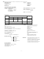
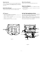
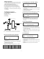
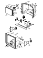
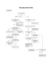
website:http://biz.LGservice.com
e-mail:http://www.LGEservice.com/techsup.html
COLOR TV
SERVICE MANUAL
CHASSIS : MC-007A
MODEL:CT-25/29Q47E/P/EN/EX
MODEL:CT-25/29Q46EN CF-29F84
CAUTION
BEFORE SERVICING THE CHASSIS,
READ THE SAFETY PRECAUTIONS IN THIS MANUAL.
CONTENTS
Contents ................................................................................................................. 2
Safety Precautions ............................................................................................3
Specifications ..................................................................................................... 4
Control Descriptions ........................................................................................ 5
Disassembly Instructions ............................................................................. 8
Adjustment Instructions ............................................................................... 9
Exploded View .................................................................................................. 14
Exploded View Parts List ..............................................................................15
Replacement Parts List ................................................................................ 16
SVC. Sheet ................................................................................................................
- 2 -
SAFETY PRECAUTIONS
IMPORTANT SAFETY NOTICE
Many electrical and mechanical parts in this chassis have special safety-related characteristics. These parts are identified by
in
the Schematic Diagram and Replacement Parts List.
It is essential that these special safety parts should be replaced with the same components as recommended in this manual to
prevent X-RADIATION, Shock, Fire, or other Hazards.
Do not modify the original design without permission of manufacturer.
General Guidance
Before returning the receiver to the customer,
An lsolation Transformer should always be used during
the servicing of a receiver whose chassis is not isolated from
the AC power line. Use a transformer of adequate power rating
as this protects the technician from accidents resulting in
personal injury from electrical shocks.
always perform an AC leakage current check on the exposed
metallic parts of the cabinet, such as antennas, terminals, etc.,
to be sure the set is safe to operate without damage of
electrical shock.
Leakage Current Cold Check(Antenna Cold Check)
It will also protect the receiver and it's components from being
damaged by accidental shorts of the circuitary that may be
inadvertently introduced during the service operation.
If any fuse (or Fusible Resistor) in this TV receiver is blown,
replace it with the specified.
When replacing a high wattage resistor (Oxide Metal Film
Resistor, over 1W), keep the resistor 10mm away from PCB.
Keep wires away from high voltage or high temperature parts.
Due to high vacuum and large surface area of picture tube,
extreme care should be used in handling the Picture Tube.
Do not lift the Picture tube by it's Neck.
X-RAY Radiation
Warning:
The source of X-RAY RADIATION in this TV receiver is the
High Voltage Section and the Picture Tube.
For continued X-RAY RADIATION protection, the
replacement tube must be the same type tube as specified in
the Replacement Parts List.
To determine the presence of high voltage, use an accurate
high impedance HV meter.
With the instrument AC plug removed from AC source,
connect an electrical jumper across the two AC plug prongs.
Place the AC switch in the on positioin, connect one lead of
ohm-meter to the AC plug prongs tied together and touch other
ohm-meter lead in turn to each exposed metallic parts such as
antenna terminals, phone jacks, etc.
If the exposed metallic part has a return path to the chassis, the
measured resistance should be between 1MΩ and 5.2MΩ.
When the exposed metal has no return path to the chassis the
reading must be infinite.
An other abnormality exists that must be corrected before the
receiver is returned to the customer.
Leakage Current Hot Check (See below Figure)
Plug the AC cord directly into the AC outlet.
Do not use a line Isolation Transformer during this check.
Connect 1.5K/10watt resistor in parallel with a 0.15uF capacitor
between a known good earth ground (Water Pipe, Conduit, etc.)
and the exposed metallic parts.
Measure the AC voltage across the resistor using AC
voltmeter with 1000 ohms/volt or more sensitivity.
Reverse plug the AC cord into the AC outlet and repeat AC
voltage measurements for each esposed metallic part. Any
voltage measured must not exceed 0.75 volt RMS which is
corresponds to 0.5mA.
In case any measurement is out of the limits sepcified, there is
possibility of shock hazard and the set must be checked and
repaired before it is returned to the customer.
Leakage Current Hot Check circuit
Adjust brightness, color, contrast controls to minimum.
Measure the high voltage.
The meter reading should indicate
23.5 ¡ 1.5KV: 14-19 inch, 26 ¡ 1.5KV: 19-21 inch,
29.0 ¡ 1.5KV: 25-29 inch, 30.0 ¡ 1.5KV: 32 inch
If the meter indication is out of tolerance, immediate service
and correction is required to prevent the possibility of
premature component failure.
AC Volt-meter
To Instrument's
exposed
METALLIC PARTS
Good Earth Ground
such as WATER PIPE,
CONDUIT etc.
0.15uF
1.5 Kohm/10W
- 3 -
SPECIFICATIONS
Note : Specification and others are subject to change without notice for improvement.
SOUND IF :
¡ Video input system:
PAL-B/G, D/K, I/I
SECAM-B/G, D/K/L/L’
NTSC M
NTSC 4.43(AV)
¡ Intermediate Frequency (Unit : MHz)
VISION IF : 38.9MHz,33.9MHz(SECAM-L’)
COLOR IF : 34.47MHz(4.43)
35.32MHz(3.58)
: NTSC-M
VIF-4.25000MHz
(
): SECAM
VIF-4.40625MHz
33.4MHz (B/G)
32.9MHz (I/I)
32.4MHz (D/K,L)
34.4MHz (M)
40.4MHz (L’)
¡ Power requirement : 110~240V, 50/60Hz
¡ Power consumption : 25”:125W
29”:135W
¡ CPT : True Flat CPT(Flatron)
¡ Tuning range
Band
For TV
B/G
D/K
VHF-Low
Ch2-4
Ch1-5
VHF-High
Ch5-12
Ch6-12
For CATV
I/I
NTSC
S1'-S3', S1
Ch4-13
Ch2-13
S2-S10,
S11-S20
Hyper
S21-S41
UHF
Ch21-69
Ch14-69
¡ Tuning system :
FVS
100 Programme memory
200 Programme memory(For CHINA)
¡ Antenna input impedance : VHF/UHF 75 ohm, unbalanced
¡ OSD (On Screen Display) : MENU Type
¡ Voice coil impedance : 8 ohm
¡ Sound output : 12W+12W
Dual/Stereo : A2/NICAM(Option)
¡ Feature : Auto programme/Manual programme
SVM (Scanning Velocity Modulation)
Digital Eye
Digital Comb Filter
Auto Sleep
Dynamic Focus
Programme Editing
PSM (Picture Status Memory)
CTI
Double Window Teletext (TOP/FLOF)
Turbo Search, Picture & Sound
ACMS
ARC (Zoom 1/ZOOM 2, 16:9¡Œ4:3)
1 TUNER PIP(Double Window PIP)
¡ External connection :
Front or
Side
Back
Head Phone Jack
S-VIDEO in
A/V in :1 pair
Scart 1(Full)
A/V in/out
Scart 2(Half)+Audio out
A/V in/out
Child Lock :
¡ External In/Output
Audio-In:0.5Vrms¡ 3db,over 10Kohm
Audio-Out:0.5Vrms¡ 3db,below 1Kohm
Video-In/Out:1Vp-p¡ 3db,75ohm
R,G,B In:0.7Vp-p¡ 3db
- 4 -
In the Lock On state the TV can only be
operated by the Remote Controller.
If any button on the front panel is pressed,
"Child Lock" is displayed on the screen but
the button's function is not performed.
To cancel of this mode, select lock off with
menu button on remote controller only.
DESCRIPTION OF CONTROLS
All the functions can be controlled with the remote control handset.
Some functions can also be adjusted with the buttons on the front
panel of the set.
POWER
10
ARC
2
Remote control handset
MUTE
1
1
2
3
4
5
6
TV/AV
Before you use the remote control handset, please install the bat11 teries. See the next page.
12
SOUND
7
8
9
MENU PICTURE
13
2. NUMBER BUTTONS
switches the set on from standby or directly select a number.
0
3
TURBO
PR
VOL
4
OK
1. POWER
switches the set on from standby or off to standby.
3. MENU
selects a menu.
VOL
PR
5
REW
PLAY
FF
P/STILL
STOP
REC
LIST
6
7
PSM
SSM
EYE/
8
TEXT/
I/II
PIP
MIX
TIME
REVEAL ? SLEEP M
SIZE
STILL
POSITION
9
PR-
PR+
SWAP
9/4PIP i
4.
14
15
16
/ E (Programme Up/Down)
selects a programme or a menu item.
switches the set on from standby.
F / G (Volume Up/Down)
adjusts the volume.
adjusts menu settings.
OK
accepts your selection or displays the current mode.
D
17 5. VCR BUTTONS (option)
control a LG video cassette recorder.
INPUT
18
6. SSM (Sound Status Memory)
recalls your preferred sound setting.
7. PSM (Picture Status Memory)
recalls your preferred picture setting.
8. EYE/ (option)
switches the eye function on or off.
*
(With teletext / PIP)
9. TELETEXT BUTTONS (option)
These buttons are used for teletext.
For further details, see the ÔTeletextÕ section.
EYE/
MIX
TEXT/
TIME
10. MUTE
switches the sound on or off.
REVEAL ? SLEEP M
9
i
11. ARC (Aspect Ratio Control)
changes the picture format.
Q.VIEW
18
(With teletext / Without PIP)
12. TV/AV
selects TV or AV mode.
clears the menu / text from the screen.
switches the set on from standby.
13. TURBO PICTURE / SOUND BUTTON
selects Turbo picture / sound.
- 5 -
14. LIST
displays the programme table.
15. I/II
selects the language during dual language broadcast (option).
selects the sound output.
16. PIP BUTTONS (option)
PIP
switches the sub picture on or off.
PR +/selects a programme for the sub picture.
SWAP
alternates between main and sub picture.
INPUT
selects the input mode for the sub picture.
SIZE
adjusts the sub picture size.
STILL
freezes motion of the sub picture.
POSITION
relocates the sub picture in clockwise direction.
9/4 PIP
switches on or off the 9 or 4 sub pictures.
POWER
MUTE
10
1
2
1
2
3
4
5
6
7
8
9
TV/AV
MENU
12
0
3
PR
4
17. SLEEP
sets the sleep timer.
VOL
Q.VIEW
OK
VOL
LIST
PR
14
18
18. SWAP or Q.VIEW
returns to the previously viewed programme.
11
COLOURED BUTTONS
These buttons are used for teletext (only TELETEXT models) or 8
programme edit.
7
Battery installation
EYE/
ARC
I/II
PSM
SSM
SLEEP
PICTURE SOUND
TURBO
The remote control handset is powered by two AAA or AA type bat- 13
teries. To load the batteries, turn the remote control handset over
and open the battery compartment. Install two batteries as indicated by the polarity symbols ( + and - ) marked inside the compartment.
(Without teletext / PIP)
AAA
AA
Note : To avoid damage from possible battery leakage, remove the
batteries if you do not plan to use the remote control handset for an
extended period of time.
- 6 -
3
15
6
1
3
4
2 6
5
1. MAIN POWER
switches the set on or off.
2. POWER/STANDBY INDICATOR
illuminates brightly when the set is in standby mode.
dims when the set is switched on.
8
3. MENU
selects a menu.
4. OK
accepts your selection or displays the current mode.
AV2
VIDEO
F
/ G (Volume Up/Down)
adjusts the volume.
adjusts menu settings.
7
/ E (Programme Up/Down)
selects a programme or a menu item.
switches the set on from standby.
L
MONO
AUDIO
D
R
5. EYE
adjusts picture according to the surrounding conditions.
6. REMOTE CONTROL SENSOR
7. AUDIO/VIDEO IN SOCKETS (AV2)
Connect the audio/video out sockets of external equipment to
these sockets.
8. HEADPHONE SOCKET
Connect the headphone plug to this socket.
- 7 -
DISASSEMBLY INSTRUCTIONS
Important note
Chassis Assy Removal
This set is disconnected from the power supply through the
converter transformer. An isolating transformer is necessary
for service operations on the primary side of the converter
transformer.
Grasp both side of Frame and pull it backward smoothly.
Back Cabinet Removal
Remove the screws residing on the back cabinet and carefully
separate the back cabinet from the front cabinet. (Fig. 2-1).
Speaker Assy Removal
1. Remove P1651 and P1652 connector from Main2 (Power/Def./
Sound-Amp) Board.
2. Remove respective 6 screws for speaker on the front
cabinet. (Fig. 2-2).
CPT Removal
PICTURE TUBE HANDLING CAUTION
1. Pull out the CPT board from the CPT neck.
2. Place the front cabinet on soft material not to mar the front
surface or damage control knobs.
3. Remove 4 screws securing the picture tube mounting
brackets to the front cabinet.
4. Carefully separate CPT from the front cabinet.
Due to high vacuum and large surface area of picture tube, great
care must be exercised when handling picture tube. Always lift
picture tube by grasping it firmly around faceplate.
NEVER LIFT TUBE BY ITS NECK! The picture tube must not be
scratched or subjected to excessive pressure as fracture of
glass may result in an implosion of considerable violence which
can cause personal injury or property damage.
CPT
board
Remove
Screws
POWER
PCB
A/V PCB
VCD PCB
STEREO
PCB
Fig. 2-1
Main PCB
Fig. 2-2
- 8 -
ADJUSTMENT INSTRUCTIONS
¡ Safety Precautions
1. It is safe to adjust after using insulating transformer between
the power supply line and chassis input to prevent the risk of
electric shock and protect the instrument.
2. Never disconnect leads while the TV receiver is on.
3. Don't short any portion of circuits while power is on.
4. The adjustment must be done by the correct appliances.
5. Unless otherwise noted, set the line voltage to 230Vac¡
10%, 50Hz.
5. The adjustment of TVshould be performed after warming up
for 15 minutes.
¡ LÕ VCO Adjustment (For SECAM-LÕ MODEL)
RF signal generator (with pattern generator)
DC Power Supply
Multimeter (volt meter)
Oscilloscope
Color analyzer
V
IC101
TDA4470
Adjust
: VR122
¡ RF AGC (Automatic Gain Control) Adjustment
Test Point
: TP 2(J15)
Adjust
: VR121
1) Input PAL-B/G 05 CH.
2) Connect Multimeter to TP2(J15),AGC adjustment point.
3) Adjust VR121 until the voltage of Multimeter becomes
2.5¡ 0.1V.
Multimeter or Oscilloscope
IC102(KI7805)
: TP1
1) Connect the measuring equipment to the Main Board as
shown in Fig.1.
2) Set RF frequency and output level of RF SIGNAL
GENERATOR as shown Table 1.
3) Turn on S1,S3 and off S2.
2) Adjust VR122 so that the DC Voltage may be 2.4¡ 0.05Vdc.
¡ Test Equipment required
1.
2.
3.
4.
5.
Test Point
1
¡ Screen Voltage Adjustment
R108
9V
R144
0.01uF
22
TP1(VCO)
7 JP1
38.9MHz (B/G,D/K,I,L)
34.25MHz (SECAM-L')
PowerSupply
5V
L104
14
S3
JP2
100 ohm
S2
Adjust
: Screen Control of FBT
1) Tune the RF Modulator to receive a PAL or SECAM signal.
2) Press MIX button on remote controller for Service to get into
the Screen Adjust Mode.
3) Adhere the Color Analyzer on the White window of CPT
face.
4) Adjust Screen Volume of FBT so that the luminance of White
window is 12¡ 1 FL.
S1
Q122
: CPT Face
13
4.7 Kohm
100 ohm
Test Point
VR122
JP3
Fig. 1 : Connection Diagram of Equipment for PIF Adjustment
¡ Focus Adjustment
¡ PIF (Picture Intermediate Frequency) Adjustment
Test Point
: TP1
Adjust
: L104
1) Connect the measuring equipment to the Main Board as
shown in Fig.1.
2) Set RF frequency and output level of RF SIGNAL
GENERATOR as shown Table 1.
3) Turn off S1 and S3 and on S2.
4) Adjust L104 so that the DC voltage may be 2.4¡ 0.05Vdc.
System
Frequency
Modulation
Output level
Adjust
B/G,D/K/I,SECAM-L
38.9MHz
OFF
10mVp-p
L104
SECAM-LÕ
34.25MHz
OFF
10mVp-p
VR122
(Table 1)
- 9 -
Test Point
: Observing Display
Adjust
: Focus control of FBT
1) Tune the TV set to receive a digital pattern.
2) Adjust the upper Focus volume of FBT for the best focus of
vertical line B.
3) Adjust the lower Focus volume of FBT for the best focus of
area A.
4) Repeat above step 2) and 3) for the best overall focus.
EP (East west Parabolar)
Adjust so that middle portion of the outermost left and right
vertical line looks like parallel with vertical lines of the CPT.
A
B
EC (East-west Coner)
Adjust so that the vertical line at every 4 corners of the
screen looks like parallel with the vertical lines of the CPT.
ET (East-west Trapezium)
Adjust to make the length of top horizontal line same with
it of the bottom horizontal line.
Fig. 2
POP (POP Position)
Adjust until the distance between POP and main picture
becomes about 1mm.
b
¡ Deflection Data Adjustment (Line SVC-2)
NOTE : How to enter into the Line Service Mode with a remocon.
1.Power off.
2.Press the Red button.
3.Press the Green button.
4.Press the Yellow button.
5.Press the Cyan button.
6.Press the OK button.
7.Power On.
1. Preparation for Deflection Adjustment
1) At SVC mode, press the Yellow colored button the SVC
remocon.
And then,deflection data adjustment OSD(SVC2 mode) will
be displayed.
2) Press Channel UP/DOWN button for desirous function
Adjustment.
3) Press Volume UP/DOWN button to adjust the data.
4) Tune the TV set to receive a PAL B/G Digital pattern.
VL (Vertical Linearity)
Adjust so that the boundary line between upper and lower
half is in accord with geometric horizontal center of the CPT.
VA (Vertical Amplitude)
Adjust so that the circle of a digital circle pattern may be
located within the effective screen of the CPT.
SC (Vertical “S” Correction)
Adjust so that all distance between each horizontal lines
are to be the same.
VS (Vertical Shift)
Adjust so that the horizontal center line of a digital circle
pattern is in accord with geometric horizontal center of
the CPT.
HS (Horizontal Shift)
Adjust so that the vertical center line of a digital circle pattern
is in accord with geometric vertical center of the CPT.
Menu
Range
29Ó Flat
VS
0600H~0900H
07D2
VA
0050H~00CFH
0095
VL
0025H~00BFH
0001
SC
0000H~009FH
00D9
HS
0000H~003FH
001E
EW
0400H~0EFFH
0A9D
ET
0700H~08FFH
07FF
EP
06E0H~0840H
0787
ES
06A0H~0AFFH
0815
EC
0790H~08E0H
0850
POP P
0790H~08E0H
000B
29Ó S-Flat
(Table 2)
¡ White Balance Adjustment.(LINE SVC 1)
NOTE : This adjustment should be performed after screen
voltage adjustment.
1) Tune the TV set to receive an 100% white pattern.
2) Press the Yellow button on remote controller in the SVC
Mode.
3) Press PSM (RED) button on remote controller. (Standard
picture)
4) Press PR+ or PR- button for desirous function adjustment.
5) Adjust Low Light status of CR and CB with VOL+ or VOLat CG:50 until X=268¡ 8,Y=273¡ 8.
6) Adjust High Light status of RG and BGB with VOL+ or
VOL- at CG:370 until X=268¡ 8,Y=273¡ 8.
7) Repeat above step 5) and 6) until each status of High Light
and Low Light for X=288¡ 8,Y=295¡ 8 with color
analyzer(color temperature 9000oK).
EW (Horizontal Width)
Adjust to that a digital circle pattern looks like exact circle.
- 10 -
Menu
Range
DATA
CR
0 ~ 511
50
CG
0 ~ 511
50
CB
0 ~ 511
50
RG
0 ~ 511
370
GG
0 ~ 511
370
BG
0 ~ 511
370
(Table 3)
¡ SVC Data & PSM,SSM Data.
Table 1. ABL Data (LINE SVC-3)
Menu
Range
29Ó Flat
IBRM
0~1FFH
00C8
WDRM
0~3FFH
0190
BCLTH
0~7FFH
0065
BCLTM
0~1FFH
000B
BCLGA
0~1FFH
0007
29Ó S-Flat
DVCO
SVGA
0008
SVDEL
0005
SVD1
0003
LDLY
0001
HBST
0~01FF
00F0
HBSO
0~01FF
0158
Table 2. SOUND PRE-SCALER (LINE SVC-4)
Menu
Range
DATA
FP
0~127
0011
NP
0~127
0045
SP
0~127
001E
S1 VOL
0~127
0042
S2 VOL
0~127
0042
Table 3. PSM Data
Mode
STANDARD DYNAMIC
MILD
GAME
CONTRAST
90
100
60
50
BRIGHT
50
55
60
60
COLOR
50
60
40
40
SHARPNESS
50
60
40
30
- 11 -
¡ OPTION Adjustment (LINE-SERVICE OPTION)
Table 4. OPTION Function
Menu
Option 1
OPTION
1
0
GAME
GAME
X
TEXT
TEXT
X
TOP
TOP
X
Australia Only
ACMS
CH+AU
China,Australia
EYE
EYE
X
TURBO
Turbo Search
X
SCART
SCART
X
A2 ST
STEREO
X
I II SV
I/II
X
MONO
MONO
X
VOL
Middle East Africa,India VOL.
Normal VOL.
H-PH
H/Phone
DGS
Degaussing
TILT
TILT
200PRO
China Only
X
AV2
Back:JACK(2EA)
Back:JACK(1EA)
HOTEL
HOTEL
X
Option 2
Option 3
KEY
SYS
M-VOL
Option 4
OSD
T-LAN
- 12 -
X
MEMO
- 13 -
EXPLODED VIEW
943
400
913
150
153
510
170
112
P801
540
550
530
520
501
300
560
120
570
310
600
121
330
320
700
- 14 -
EXPLODED VIEW PARTS LIST
Replace only with part number specified.
Part No.
No.
Description
25"
29"
112
2426GE259AJ
2426GF239AR
CPT SET
120
6400VA0027A
6400VA0027A
SPEAKER,GENERAL H165/051800A 8 OHM 10/1
121
3110V00073A
3110V00073A
CASE,SPEAKER
150
150-D05Z
6140VC2005F
COIL,DEGAUSSING
153
6150Z-1230F
6150Z-1240A
DY
170
170-844G
170-844K
300
3091V00278F
3091V00255P
CABINET ASSY
CPT EARTH
3091V00278G
3091V00255W
CABINET ASSY *SY-BROTHERS
310
5020V00459A
5020V00459C
BUTTON,CONTROL 6KEY
320
320-062E
320-062E
330
5020V00391A
5020V00391A
BUTTON,POWER 1KEY
400
3809V00203A
3809V00188A
BACK COVER ASSY
-
3809V00188E
BACK COVER ASSY
3809V00203G
3809V00188M
BACK COVER ASSY (1SCART-1 PHONE)
501
3210V00043D
3210V00043D
FRAME 29Q47EX MAIN
3210V00043A
3210V00043A
FRAME 29Q47E MAIN
510
6871VSMB41A
6871VSMB41B
PWB ASSY,CPT 007A W/SVM,LGESY8
520
-
6871VMMA98C
PWB ASSY,MAIN 29Q47EX
-
6871VMMA98E
PWB ASSY,MAIN 29Q47E LGEGF
-
6871VMMA98F
PWB ASSY,MAIN 29Q47E LGEIN
-
6871VMMA98U
PWB ASSY,MAIN 29Q47P BUTTERFLY
6871VMMA98P
6871VMMA98K
PWB ASSY,MAIN 29Q47E BROTHERS
6871VMMA98M
6871VMMA98L
PWB ASSY,MAIN Q46EN JEB
530
540
SPRING,KNOB
6871VSMB39E
6871VSMB39D
PWB ASSY,VCD 007A W/O(SVHS,PIP)
6871VSMB39B
6871VSMB39B
PWB ASSY,VCD 007A W/O(SVHS,PIP)
-
6871VSM625G
PWB ASSY,W/PIP,SY
-
6871VSMB40B
PWB ASSY,AUDIO 007A A/V STEREO
-
6871VSMB40C
PWB ASSY,AUDIO 007A A/V STEREO
6871VSMD20A
6871VSMD20A
PWB ASSY,AUDIO 007A RF STEREO,
550
-
6871VSMB47A
PWB ASSY,HV 007A Q46 D_FOCUS,LGESY8
560
-
6871VSMB43A
PWB ASSY,CONT 007A M66 CONTROL,LGESY8
6871VSMB43D
6871VSMB43B
PWB ASSY,CONT Q46
-
6871VSMB44B
PWB ASSY,POWER 007A Q46 S_POWER,LGESY8
6871VSMB44E
6871VSMB44E
PWB ASSY,POWER 007A Q46 S_POWER JEB
-
6871VSMB42B
PWB ASSY,A/V 007A Q46 SIDE A/V,LGESY8
PWB ASSY,A/V 007A Q46 SIDE A/V
570
600
6871VSMB42C
6871VSMB42E
700
0IGL120104A
0IGL120104A
913
332-229H
332-229H
943
1PTF0403116
1PTF0403116
SCREW,TAP TITE(P) D4.0 L16.0 MSWR3/FZB
174-009V
174-009V
POWER CORD(W/HOLD,HOUSING)L=400,4.0
P801
IC,CDS SENSOR MODULE(P1201-04)
SCREW ASSY HEXAGON HEAD (L:40,D:18)
- 15 -
The components identified by mark
are
critical for safety.
Replace only with part number specified.
LOCA. NO
PART NO
REPLACEMENT PARTS LIST
DESCRIPTION
IC
D850
0ISK100300A
IC,SLA1003 SIP12 BK DIODE MODULE(
HIC181
0IZZVF0016A
IC TILT 7P,SIP BK .
IC01
0ICTMIH001B
IC,SDA5555-A030 INFINEON 52SDIP S
ICV01
0IIT312000A
IC,VDP3120B 64P SDIP BK VCD IC (5
ICN01
0IIT341000J
IC,MSP3410D-C5 52P SDIP BK MULTI
ICP01
0IIT312000A
IC,VDP3120B 64P SDIP BK
IC02
0IAL241610B
IC,AT24C16-10PC-2.7 8PIN DIP ST E
ICV02
0IFA754207A
IC,KA75420ZTA(KA7542ZTA) 3P,TO-92
ICN02
0ISG282200A
IC,TDA2822M 8D DUAL AUDIO AMP(1W)
ICP02
0IFA754207A
IC,KA75420ZTA(KA7542ZTA) 3P,TO-92
IC03
0IFA752700A
IC,KA75270Z 3 TP RE-SET IC MC-007
ICN03
0IKE780500Q
IC,KIA7805API 3P TO-220 ST REGULA
IC04
0ISG111733B
IC,LD1117V33C 3SIP ST REGULATOR
ICN05
0IFA753307A
IC,KA75330ZTA(KA7533ZTA) 3P,TO-92
IC101
0ITF447000A
IC,TDA4470M 28P,SDIP BK VIF+SIF
ICP101
0ISO204000A
IC,CXA2040AQ 32P QFP BK
IC102
0IKE780500Q
IC,KIA7805API 3P TO-220 ST REGULA
ICP102
0ISM948900A
IC,SDA9489 28 PIN SOP
ICP103
0ISG111733B
LD1117V33C 3SIP ST
IC301
0ISA784500A
IC,LA7845 7SIP V/OUT(1.5A)
IC302
0IKE455800E
IC,KIA4558 8DIP DUAL OP AMP
IC601
0ISA428200A
IC,LA4282 12S 2CHX10W AUDIO AMP
IC801
0ISK665613B
IC,STR-F6656(LF1352) 5P,SIP BK ST
IC802
0ILI817000G
IC,LTV817M-VB 4P,DIP BK PHOTO COU
IC803
0ILI817000G
IC,LTV817M-VB 4P,DIP BK PHOTO COU
IC851
0IKE780500Q
IC,KIA7805API 3P TO-220 ST REGULA
IC853
0ISH092100B
IC,PQ09RD21 4SIP ST REGULATOR
IC855
0ISS278050A
IC,KA278R05 4P,TO-220F BK LOW DRO
IC856
0ISK115000A
IC,SE115N(LF12) 3P 115V ERROR AMP
IC901
0ISG510900A
IC,STV5109 15SIP ST RGB DRIVE
Q07
0IFA270000A
IC,2N7000TA TO-92, 3P TP LEVEL SH
Q08
0IFA270000A
IC,2N7000TA TO-92, 3P TP LEVEL SH
DIODE
D01
0DD414809ED
DIODE,1N4148 TA
D02
0DD414809ED
DIODE,1N4148 TA
D03
0DD414809ED
DIODE,1N4148 TA
D04
0DD414809ED
DIODE,1N4148 TA
D101
0DD414809ED
DIODE,1N4148 TA
D121
0DSVH00019A
DIODE,SWITCHING BA282
D122
0DSVH00019A
DIODE,SWITCHING BA282
D301
0DD150009CE
DIODE,RECTIFIER GP15J TP GULF
D302
0DS113379BA
DIODE,SWITCHING 1SS133 T-72 TP ROHM
D401
0DD410000AC
DIODE,RECTIFIER RU4DS,LF-L1
D402
0DD410000AD
DIODE,RECTIFIER RU4AM,LF-L1
D403
0DD150009CA
DIODE,RECTIFIER RGP15J
D404
0DR150009AB
DIODE,RECTIFIER RGP15G
D405
0DR150009AB
DIODE,RECTIFIER RGP15G
D406
0DR150009AB
DIODE,RECTIFIER RGP15G
D407
0DD414809ED
DIODE,1N4148 TA
D408
0DD100009AE
DIODE,RECTIFIER RU1A V(1)
LOCA. NO
PART NO
DESCRIPTION
D412
0DD414809ED
DIODE,1N4148 TA
D601
0DD414809ED
DIODE,1N4148 TA
D602
0DD414809ED
DIODE,1N4148 TA
D802
0DR060009AA
DIODE,RECTIFIER TVR06J TP
D803
0DD100009AM
DIODE,RECTIFIER EU1ZV(1) TP
D804
0DD414809ED
DIODE,1N4148 TA
D857
0DD414809ED
DIODE,1N4148 TA
D859
0DD420000BB
DIODE,D4L20U SHINDENGEN
D861
0DR060009AA
DIODE,RECTIFIERS TVR06J TP
D863
0DD414809ED
DIODE,1N4148 TA
D864
0DD414809ED
DIODE,1N4148 TA
D865
0DD414809ED
DIODE,1N4148 TA
D901
0DD414809ED
DIODE,1N4148 TA
D902
0DD414809ED
DIODE,1N4148 TA
D903
0DD414809ED
DIODE,1N4148 TA
D904
0DR140049AC
DIODE,RECTIFIER 1N4004A T-81
D905
0DD414809ED
DIODE,1N4148 TA
D906
0DD414809ED
DIODE,1N4148 TA
D907
0DD414809ED
DIODE,1N4148 TA
D908
0DD060009AC
DIODE,RECTIFIERS TVR06J TP
D909
0DD060009AC
DIODE,RECTIFIERS TVR06J TP
D910
0DD060009AC
DIODE,RECTIFIERS TVR06J TP
D951
0DD414809ED
DIODE,1N4148 TA
D952
0DD414809ED
DIODE,1N4148 TA
D953
0DD414809ED
DIODE,1N4148 TA
D954
0DD414809ED
DIODE,1N4148 TA
D955
0DD414809ED
DIODE,1N4148 TA
D956
0DD414809ED
DIODE,1N4148 TA
D957
0DD414809ED
DIODE,1N4148 TA
D958
0DD414809ED
DIODE,1N4148 TA
D960
0DD414809ED
DIODE,1N4148 TA
D961
0DD150009CA
DIODE,RECTIFIERS RGP15J TP
D962
0DD150009CA
DIODE,RECTIFIERS RGP15J TP
D963
0DD414809ED
DIODE,1N4148 TA
DB801
0DD560000AA
DIODE,RECTIFIER D5SB60 BRIDGE(5A/600V)
LD1101
0DL100000AE
LED,SA5711(DL-1LO)
Ò(25Ó)
0DL310800AA
LED,HTR3108BDA
DP01
0DD414809ED
DIODE,1N4148 TA
DP02
0DD414809ED
DIODE,1N4148 TA
DP03
0DD414809ED
DIODE,1N4148 TA
DV01
0DD414809ED
DIODE,1N4148 TA
DV02
0DD414809ED
DIODE,1N4148 TA
DV03
0DD414809ED
DIODE,1N4148 TA
ZD01
0DZ360009BC
DIODE,ZENERS MTZJ3.6B TP ROHM-K DO34 0.5W
ZDN01
0DZ820009AH
DIODE,ZENERS MTZJ8.2B TP ROHM-K DO34 8.2V
ZD101
0DZ330009BA
DIODE,ZENER HZT33(TP) HITACHI
ZD202
0DZ680009BB
DIODE,ZENERS MTZJ6.8B TP ROHM-K DO34 0.5W
ZD203
0DZ680009BB
DIODE,ZENERS MTZJ6.8B TP ROHM-K DO34 0.5W
ZD301
0DZ180009BE
DIODE,ZENERS GDZJ18B TP GRANDE DO34 0.5W
ZD302
0DZ560009AH
DIODE,ZENERS GDZJ5.6B TP GRANDE DO34 0.5W
ZD303
0DZ180009BE
DIODE,ZENERS GDZJ18B TP GRANDE DO34 0.5W
ZD401
0DZ510009BF
DIODE,ZENERS GDZ5.1B TP GRANDE DO34 0.5W
ZD402
0DZ510009BF
DIODE,ZENERS GDZ5.1B TP GRANDE DO34 0.5W
- 16 -
For Capacitor & Resistors,
the charactors at 2nd and 3rd
digit in the P/No. means as
follows;
LOCA. NO
ZD901
CC, CX, CK, CN : Ceramic
CQ : Polyestor
CE : Electrolytic
PART NO
0DZ180009BE
RD : Carbon Film
RS : Metal Oxide Film
RN : Metal Film
RF : Fusible
DESCRIPTION
DIODE,ZENER GDZJ18B
TRANSISTOR
The components identified by mark
are
critical for safety.
Replace only with part number specified.
LOCA. NO
PART NO
DESCRIPTION
QP14
0TR387500AA
TR,CHIP 2SC3875S(ALY) KEC
QP15
0TR150400BA
TR,CHIP 2SA1504S(ASY) KEC
QV01
0TR387500AA
TR,CHIP 2SC3875S(ALY) KEC
Q02
0TR945009AA
TR,KSC945C-Y TP SAMSUNG
QV02
0TR387500AA
TR,CHIP 2SC3875S(ALY) KEC
Q03
0TR102009AB
TR,KRC102M,TP(KRC1202),KEC
QV03
0TR387500AA
TR,CHIP 2SC3875S(ALY) KEC
Q04
0TR945009AA
TR,KSC945C-Y TP SAMSUNG
QV04
0TR387500AA
TR,CHIP 2SC3875S(ALY) KEC
Q05
0TR102009AB
TR,KRC102M,TP(KRC1202),KEC
QV05
0TR387500AA
TR,CHIP 2SC3875S(ALY) KEC
Q121
0TR945009AA
TR,KSC945C-Y TP SAMSUNG
QV06
0TR387500AA
TR,CHIP 2SC3875S(ALY) KEC
Q122
0TR945009AA
TR,KSC945C-Y TP SAMSUNG
QV07
0TR387500AA
TR,CHIP 2SC3875S(ALY) KEC
Q123
0TR733009AA
TR,KSA733C-Y TP SAMSUNG TO-92
QV08
0TR387500AA
TR,CHIP 2SC3875S(ALY) KEC
Q124
0TR945009AA
TR,KSC945C-Y TP SAMSUNG
QV09
0TR150400BA
TR,CHIP 2SA1504S(ASY) KEC
Q125
0TR319709AB
TR,KTC3197,TP(KTC388A),KEC
QV10
0TR387500AA
TR,CHIP 2SC3875S(ALY) KEC
Q126
0TR945009AA
TR,KSC945C-Y TP SAMSUNG
QV11
0TR387500AA
TR,CHIP 2SC3875S(ALY) KEC
Q201
0TR733009AA
TR,KSA733C-Y TP SAMSUNG TO-92
QV12
0TR150400BA
TR,CHIP 2SA1504S(ASY) KEC
Q221
0TR733009AA
TR,KSA733C-Y TP SAMSUNG TO-92
QV13
0TR387500AA
TR,CHIP 2SC3875S(ALY) KEC
Q301
0TR945009AA
TR,KSC945C-Y TP SAMSUNG
QV14
0TR387500AA
TR,CHIP 2SC3875S(ALY) KEC
Q303
0TR127409AB
TR,KTA1274-Y TO-92L TP KEC
QV15
0TR150400BA
TR,CHIP 2SA1504S(ASY) KEC
Q402
0TR223800AA
TR,KTC2238A-Y
Q405
0TR205900AB
TR,KTD2059-Y TO-220IS KEC
Q401
0TR258100AA
TR,2SD2581 BK SANYO TO3P -
C01
0CE476DD618
47UF STD 10V 20% FL TP 5
Q601
0TR733009AA
TR,KSA733C-Y TP SAMSUNG TO-92
C02
0CN1030F679
10000P 16V M Y TA52
Q853
0TR945009AA
TR,KSC945C-Y TP SAMSUNG
C03
0CX6200K409
62P 50V J SL TA52
Q854
0TR102009AB
TR,KRC102M,TP(KRC1202),KEC
C04
0CX6200K409
62P 50V J SL TA52
Q857
0TR320209AA
TR,KTC3202-TP-Y (KTC1959)KEC
C05
0CN1030F679
10000P 16V M Y TA52
Q901
0TR126609AA
TR,KTA1266-TP-Y (KTA1015) KEC
C08
0CN1030F679
10000P 16V M Y TA52
Q910
0TR437000BA
TR,KTC4370A-Y TO-220IS KEC
C09
0CN1030F679
10000P 16V M Y TA52
Q951
0TR320209AA
TR,KTC3202-TP-Y (KTC1959)KEC
C10
0CE106DK618
10UF STD 50V M FL TP5
Q952
0TR320209AA
TR,KTC3202-TP-Y (KTC1959)KEC
C11
0CE106DK618
10UF STD 50V M FL TP5
Q953
0TR320209AA
TR,KTC3202-TP-Y (KTC1959)KEC
C12
181-007D
MPE ECQ-V1H154JL3(TR), 50V 0.1
Q954
0TR127009AA
TR,KTA1270-TP-Y (KTA562TM)KEC
C14
0CN1040K949
0.1M 50V Z F TA52
Q955
0TR320209AA
TR,KTC3202-TP-Y (KTC1959)KEC
C17
0CN1010K519
100P 50V K B TA52
Q956
0TR320209AA
TR,KTC3202-TP-Y (KTC1959)KEC
C18
0CE476DF618
47UF STD 16V M
Q957
0TR127009AA
TR,KTA1270-TP-Y (KTA562TM)KEC
C19
0CE475DK618
4.7UF STD 50V 20% FL TP 5
Q958
0TR165900AC
TR,KTA1659A-Y TO-220IS BK KEC - -
C20
0CE476DD618
47UF STD 10V 20% FL TP 5
QN01
0TR150400BA
TR,CHIP 2SA1504S(ASY) KEC
C21
0CE107DD618
100UF STD 10V M FL TP5
QN02
0TR150400BA
TR,CHIP 2SA1504S(ASY) KEC
C22
0CN1030F679
10000P 16V M Y TA52
QP01
0TR387500AA
TR,CHIP 2SC3875S(ALY) KEC
C24
0CE225DK618
2.2UF STD 50V 20% FL TP 5
QP02
0TR387500AA
TR,CHIP 2SC3875S(ALY) KEC
C25
0CN1020K519
1000P 50V K B TA52
QP03
0TR387500AA
TR,CHIP 2SC3875S(ALY) KEC
C26
0CC3300K415
33P
50V
J NP0 TP
QP04
0TR387500AA
TR,CHIP 2SC3875S(ALY) KEC
C27
0CC3300K415
33P
50V
J NP0 TP
QP05
0TR387500AA
TR,CHIP 2SC3875S(ALY) KEC
C29
0CN1030F679
10000P 16V M Y TA52
QP06
0TR150400BA
TR,CHIP 2SA1504S(ASY) KEC
C30
0CE106DK618
10UF STD 50V M FL TP5
QP07
0TR387500AA
TR,CHIP 2SC3875S(ALY) KEC
C31
0CE106DK618
10UF STD 50V M FL TP5
QP08
0TR387500AA
TR,CHIP 2SC3875S(ALY) KEC
C32
0CN1030F679
10000P 16V M Y TA52
QP09
0TR150400BA
TR,CHIP 2SA1504S(ASY) KEC
C33
0CN1030F679
10000P 16V M Y TA52
QP10
0TR387500AA
TR,CHIP 2SC3875S(ALY) KEC
C34
0CN1030F679
10000P 16V M Y TA52
QP104
0TR387500AA
TR,CHIP 2SC3875S(ALY) KEC
C101
0CE476DK618
47UF STD 50V M FL TP5
QP105
0TR387500AA
TR,CHIP 2SC3875S(ALY) KEC
C103
0CN1030F679
10000P 16V M Y TA52
QP106
0TR387500AA
TR,CHIP 2SC3875S(ALY) KEC
C104
0CE227DD618
220UF STD 10V M FL TP5
QP11
0TR387500AA
TR,CHIP 2SC3875S(ALY) KEC
C105
0CX3300K409
33P 50V J SL TA52
QP12
0TR150400BA
TR,CHIP 2SA1504S(ASY) KEC
C106
0CX3300K409
33P 50V J SL TA52
QP13
0TR387500AA
TR,CHIP 2SC3875S(ALY) KEC
C108
0CE106DF618
10UF STD 16V M FL TP5
CAPACITOR
- 17 -
For Capacitor & Resistors,
the charactors at 2nd and 3rd
digit in the P/No. means as
follows;
The components identified by mark
are
critical for safety.
Replace only with part number specified.
LOCA. NO
PART NO
DESCRIPTION
LOCA. NO
CC, CX, CK, CN : Ceramic
CQ : Polyestor
CE : Electrolytic
PART NO
RD : Carbon Film
RS : Metal Oxide Film
RN : Metal Film
RF : Fusible
DESCRIPTION
C109
0CE335DK618
3.3UF STD 50V 20% FL TP 5
C311
0CQ1031N509
0.01U 100V K POLY
C110
0CN1040K949
0.1M 50V Z F TA52
C401
0CE474DK618
0.4700UF STD 50V M FL TP5
C112
0CN1020K519
1000P 50V K B TA52
C402
0CE475DK618
4.7UF STD 50V 20% FL TP 5
C113
0CE476DD618
47UF STD 10V 20% FL TP 5
C403
0CK2220W515
2200P 500V K B
C115
0CN1030F679
10000P 16V M Y TA52
C405
181-015R
0.022UF 1.6KV H M/PP NI FM20
C121
0CN1030F679
10000P 16V M Y TA52
Ò(25Ó)
181-015Q
0.02UF 1.6KV H
C122
0CN1030F679
10000P 16V M Y TA52
C406
181-091G
DEHR33D471KN3A 470PF 2KV 10%,-
C123
0CN1030F679
10000P 16V M Y TA52
C407
0CQZVBK004B
0.027UF D 630V J PP NI FM7.5
C124
0CN1030F679
10000P 16V M Y TA52
C408
0CE685BK652
6.8UF KME TYPE 50V 20% FM7.5 B
C125
0CN1040K949
0.1M 50V Z F TA52
C409
0CK2220W515
2200P 500V K B
C126
0CN1030F679
10000P 16V M Y TA52
C410
0CE106BR618
10UF KME 250V M FL TP5
C127
181-007H
MPE ECQ-V1H474JL3(TR), 50V 0.4
C411
181-013S
MPP 400V 0.62UF J
C128
0CE106DF618
10UF STD 16V M FL TP5
C412
0CK6810W515
680P
C129
0CN1030F679
10000P 16V M Y TA52
C413
0CE107DJ618
100UF STD 35V M FL TP5
C130
0CSZVTA001F
TAP684K035BRS(AMMO)35V 0.68UFK
C414
181-091P
SL 270PF 1KV 10%,-10% R/TP TP5
C131
0CN1030F679
10000P 16V M Y TA52
C415
0CE108BH618
1000UF KME 25V M FL TP5
C132
0CN1030F679
10000P 16V M Y TA52
C416
181-009R
PP 200V 0.022UF K
C134
0CE476DD618
47UF STD 10V 20% FL TP 5
C417
0CK2710W515
270P
C135
0CN1040K949
0.1M 50V Z F TA52
C419
0CE108DH618
1000UF STD 25V M FL TP5
C136
0CE226DF618
22UF STD 16V M FL TP5
C420
181-010B
PP 400V 0.056UF J
C137
181-007H
MPE ECQ-V1H474JL3(TR), 50V 0.4
C421
0CK2710W515
270P
C138
0CN1040K949
0.1M 50V Z F TA52
C422
0CE106DR618
10UF STD 250V M FL TP5
C139
0CE104DK618
0.1000UF STD 50V M FL TP5
C517
0CQ1531N509
0.015U 100V K POLY
TP
C140
0CN1030F679
10000P 16V M Y TA52
C518
0CQ1531N509
0.015U 100V K POLY
TP
C141
0CE107DD618
100UF STD 10V M FL TP5
C519
0CQ1531N509
0.015U 100V K POLY
TP
C147
0CX4700K409
47P 50V J SL TA52
C601
0CE107DH618
100UF STD 25V M FL TP5
C148
0CX4700K409
47P 50V J SL TA52
C602
0CE684DK618
0.68UF STD 50V 20% FL TP 5
C149
0CE106DF618
10UF STD 16V M FL TP5
C603
0CQ5621N509
0.0056U 100V K POLY
C181
0CN1030F679
10000P 16V M Y TA52
C604
0CE107DH618
100UF STD 25V M FL TP5
C182
0CE476DF618
47UF STD 16V M FL TP5
C605
0CE684DK618
0.68UF STD 50V 20% FL TP 5
C183
0CE227DF618
220UF STD 16V M FL TP5
C606
0CQ5621N509
0.0056U 100V K POLY
C184
0CQ1041N509
0.1U 100V
C607
0CE107DH618
100UF STD 25V M FL TP5
C185
0CC3900K415
39P
50V
J NPO TP
C608
0CQ1041N509
0.1U 100V
C186
0CC3900K415
39P
50V
J NPO TP
C609
0CE477DJ618
470UF STD 35V 20% FL TP 5
C201
0CE227DF618
220UF STD 16V M FL TP5
C610
0CQ1041N509
0.1U 100V
C208
0CE226DF618
22UF STD 16V M FL TP5
C611
0CE477DJ618
470UF STD 35V 20% FL TP 5
C209
0CE226DF618
22UF STD 16V M FL TP5
C612
0CN1040K949
0.1M 50V Z F TA52
C221
0CE476DF618
47UF STD 16V M FL TP5
C613
0CE477DK618
470UF STD 50V 20% FL TP 5
C222
0CE227DF618
220UF STD 16V M FL TP5
C614
0CE477DH618
470UF STD 25V M FL TP5
C229
0CE226DF618
22UF STD 16V M FL TP5
C802
0CQZVBK002C
A.C 275V 0.22UF K (S=22.5)
C230
0CE226DF618
22UF STD 16V M FL TP5
C803
181-091G
DEHR33D471KN3A 470PF 2KV 10%,-
C244
0CN1010K519
100P 50V K B TA52
C804
0CE337KV6A0
330UF SLT 450V M VNSN BULK
C245
0CN1010K519
100P 50V K B TA52
C806
181-011C
PP 1600V 0.0015UF J
C302
0CQ3341N401
0.33U 100V J POLY
F5
C807
181-091G
DEHR33D471KN3A 470PF 2KV 10%,-
C303
0CE107BK618
100UF KME 50V M FL TP5
C808
0CE107BJ618
100UF KME 35V M FL TP5
C304
0CQ6821N509
0.0068U 100V K POLY
C809
0CK1020K515
1000P 50V
C305
0CQ1021N509
0.001U 100V K POLY
C811
181-120K
2200PF 4KV M E FMTW LEAD 4.5
C306
0CQ3931N509
0.0390UF 100V K PE TP
C813
0CK10201515
1000P 1KV K B TS
C307
0CQ1031N509
0.01U 100V K POLY
C814
0CQZVBK002A
A.C 275V 0.1UF M (S=15)
C308
0CE476DJ618
47UF STD 35V M FL TP5
C815
181-091Q
R 470PF 1KV 10%,-10% R/TP TP5
C309
0CN4710K519
470P 50V K B TA52
C817
0CK22201510
2200P 1KV K B S
C310
0CQ1031N509
0.01U 100V K POLY
C854
0CE107DF618
100UF STD 16V M FL TP5
K POLY
TP
TP
TP
TP
TP
- 18 -
500V K B
500V K B
500V K B
TS
TS
TS
TS
TS
K POLY
K POLY
KB
TP
TP
TP
TP
TP
TS
For Capacitor & Resistors,
the charactors at 2nd and 3rd
digit in the P/No. means as
follows;
LOCA. NO
CC, CX, CK, CN : Ceramic
CQ : Polyestor
CE : Electrolytic
PART NO
RD : Carbon Film
RS : Metal Oxide Film
RN : Metal Film
RF : Fusible
DESCRIPTION
C855
0CE107DD618
100UF STD 10V M FL TP5
C856
0CK47101515
470P 1KV K B TS
C857
0CE228DF618
2200UF STD 16V M FL TP5
C858
0CE477DF618
470UF STD 16V 20% FL TP 5
C859
0CK47101515
470P 1KV K B TS
C860
0CE108BF618
C861
The components identified by mark
are
critical for safety.
Replace only with part number specified.
LOCA. NO
PART NO
DESCRIPTION
C1204
0CN2210K519
220P 50V K B TA52
Ò
0CN4710K519
470P 50V K B TA52
C1205
0CN2210K519
220P 50V K B TA52
Ò
0CE475DK618
4.7UF STD 50V 20%
C1206
0CN4710K519
470P 50V K
1000UF KME 16V M FL TP5
Ò
0CN1040K949
0.1M 50V Z
0CE108BF618
1000UF KME 16V M FL TP5
C1207
0CN4710K519
470P 50V K
C862
0CE475CK636
4.7UF SHL,SD 50V 20% FM5 BP(D)
C1210
0CN2210K519
220P 50V K B TA52
C863
181-091Q
R 470PF 1KV 10%,-10% R/TP TP5
C1211
0CN2210K519
220P 50V K B TA52
C864
0CE108DK61A
1000UF STD 50V M FL TP7.5
C1212
0CN1030F679
10000P 16V M
C866
0CK4710W515
470PF 500V K B TR
C1213
0CE476DD618
47UF STD 10V 20%
C867
0CE227DK618
220UF STD 50V M FL TP5
C1401
0CQ5631N409
0.0560UF 100V J PE TP
C870
181-091D
DEHR33A102KN2A 1000PF 1KV 10%,
C1403
0CQ1531N509
0.015U 100V K POLY
C871
0CE227DP650
220UF STD 160V M FM7.5 BULK
CH19
0CE107DF618
100UF STD 16V M FL TP5
C872
0CE107CP618
100U SHL 160V M FL TP5
CN05
0CE107DF618
100UF STD 16V M FL TP5
C873
0CQ1041N509
0.1U 100V
CN07
0CE335DK618
3.3UF STD 50V 20% FL TP 5
C901
0CX1500K409
15P 50V J SL TA52
CN10
0CK224DF56A
220000PF 2012 16V 10% R/TP X7R
C902
0CX5R60K509
5.6P 50V K SL TA52
CN11
0CK224DF56A
220000PF 2012 16V 10% R/TP X7R
C903
0CX2200K409
22P 50V J SL TA52
CN12
0CK224DF56A
220000PF 2012 16V 10% R/TP X7R
C904
0CE107DF618
100UF STD 16V M FL TP5
CN13
0CK224DF56A
220000PF 2012 16V 10% R/TP X7R
C905
0CN2230H949
22000P 25V Z FTA52
CN16
0CE106DF618
10UF STD 16V M FL TP5
C906
0CE106DR618
10UF STD 250V M FL TP5
CN20
0CE107DF618
100UF STD 16V M FL TP5
C907
0CQZVBK002A
A.C 275V 0.1UF M (S=15)
CN21
0CE107DF618
100UF STD 16V M FL TP5
C908
0CE475DR618
4.7UF STD 250V 20% FL TP 5
CN23
0CE107DF618
100UF STD 16V M FL TP5
C909
0CK1020W515
1000P 500V K B
TS
CN24
0CE476DF618
47UF STD 16V M FL TP5
C910
0CK1020W515
1000P 500V K B
TS
CN29
0CE106DF618
10UF STD 16V M FL TP5
C911
0CK1020W515
1000P 500V K B
TS
CN30
0CE106DF618
10UF STD 16V M FL TP5
C912
0CE476DF618
47UF STD 16V M FL TP5
CN32
0CE107DF618
100UF STD 16V M FL TP5
C913
0CK22202515
2200PF 2KV K B TR
CN34
0CE106DF618
10UF STD 16V M FL TP5
C951
0CK1040K945
0.1UF 50V Z F TR
CN35
0CK224DF56A
220000PF 2012 16V 10% R/TP X7R
C952
0CE107DK618
100UF STD 50V M
CN36
0CK224DF56A
220000PF 2012 16V 10% R/TP X7R
C953
0CE106DF618
10UF STD 16V M FL TP5
CN37
0CK224DF56A
220000PF 2012 16V 10% R/TP X7R
C954
0CE106DF618
10UF STD 16V M FL TP5
CN38
0CK224DF56A
220000PF 2012 16V 10% R/TP X7R
C955
0CE106DF618
10UF STD 16V M FL TP5
CN39
0CK224DF56A
220000PF 2012 16V 10% R/TP X7R
C956
0CSZVTA001F
TAP684K035BRS(AMMO)35V 0.68UFK
CN40
0CK224DF56A
220000PF 2012 16V 10% R/TP X7R
C957
0CSZVTA001F
TAP684K035BRS(AMMO)35V 0.68UFK
CN41
0CK224DF56A
220000PF 2012 16V 10% R/TP X7R
C958
0CE106DP618
10UF STD 160V M FL TP5
CN42
0CK224DF56A
220000PF 2012 16V 10% R/TP X7R
C959
0CN1010K519
100P 50V K B TA52
CN43
0CK224DF56A
220000PF 2012 16V 10% R/TP X7R
C960
0CK4720W510
4700P 500V K B S
CN44
0CK224DF56A
220000PF 2012 16V 10% R/TP X7R
C961
0CN1010K519
100P 50V K B TA52
CN45
0CK224DF56A
220000PF 2012 16V 10% R/TP X7R
C962
0CK4720W510
4700P 500V K B S
CN46
0CK224DF56A
220000PF 2012 16V 10% R/TP X7R
C963
0CE107DF618
100UF STD 16V M FL TP5
CN47
0CE106DF618
10UF STD 16V M FL TP5
C964
0CE107DF618
100UF STD 16V M FL TP5
CN49
0CK224DF56A
220000PF 2012 16V 10% R/TP X7R
C965
0CE106DP618
10UF STD 160V M FL TP5
CN50
0CK224DF56A
220000PF 2012 16V 10% R/TP X7R
C966
0CK1010W515
100P
CN53
0CE106DF618
10UF STD 16V M FL TP5
C967
0CN2210K519
220P 50V K B TA52
CN54
0CX5600K409
56P 50V J SL TA52
C1101
0CE107DD618
100UF STD 10V M
CN59
0CE107DF618
100UF STD 16V M FL TP5
Ò(25Ó)
0CE475DK618
4.7UF STD 50V 20
CP06
0CE106DF618
10UF STD 16V M FL TP5
C1201
0CN2710K519
270P 50V K B TA52
CP10
0CE335DK618
3.3UF STD 50V 20% FL TP 5
Ò
0CN4710K519
470P 50V K B TA52
CP108
0CE476DF618
47UF STD 16V M FL
C1202
0CN2210K519
220P 50V K B TA52
CP109
0CE477DD618
470UF STD 10V M FL
C1203
0CN2210K519
220P 50V K B TA52
CP11
0CQ3331N509
0.0033U 100V K POLY
K POLY
500V K B
TP
TS
- 19 -
TP
TP
For Capacitor & Resistors,
the charactors at 2nd and 3rd
digit in the P/No. means as
follows;
The components identified by mark
are
critical for safety.
Replace only with part number specified.
LOCA. NO
PART NO
DESCRIPTION
LOCA. NO
CC, CX, CK, CN : Ceramic
CQ : Polyestor
CE : Electrolytic
PART NO
RD : Carbon Film
RS : Metal Oxide Film
RN : Metal Film
RF : Fusible
DESCRIPTION
CP110
181-442Z
PE,ECQ -B1H104KF3
CV47
0CK224DF56A
220000PF 2012 16V 10% R/TP X7R
CP111
181-442Z
PE,ECQ -B1H104KF3
CV63
0CE226DF618
22UF STD 16V M FL TP5
CP112
181-442Z
PE,ECQ -B1H104KF3
CP12
0CQ3331N509
0.033U 100V K POLY
CP121
0CE476DF618
47UF STD 16V M FL TP5
HJ1001
380-068B
JACK,PHONE 3.5
CP123
0CE476DF618
47UF STD 16V M FL TP5
JK201
6612VJH011C
JACK,RCA PPJ109C A/V IN/OUT 6
CP125
0CE476DF618
47UF STD 16V M FL TP5
Ò
6612VMH001A
JACK,SCART UPJ-R1 018
CP128
0CE105DK618
1UF STD 50V M
JK202
6612VJH011C
JACK,RCA PPJ109C A/V IN/OUT 6
CP130
0CE105DK618
1UF STD 50V M
JK1201
6613V00004B
JACK ASSY,+3P
CP131
181-442Z
PE,ECQ -B1H104KF3
PJ1001
6613V00004B
JACK ASSY,+3P
CP139
0CE476DF618
47UF STD 16V M FL TP5
CP14
0CE106DF618
10UF STD 16V M FL TP5
CP140
0CE106DF618
10UF STD 16V M FL TP5
J29
0LA0102K119
INDUCTOR,10UH K 2.3*3.4 TP
CP142
0CE106DF618
10UF STD 16V M FL TP5
J51
0LA0182K119
INDUCTOR,18UH K 2.3*3.4 TP
CP143
0CE107DF618
100UF STD 16V M FL TP5
JV26
0LA0391K119
INDUCTOR,3.9UH K 2.3*3.4 TP
CP145
0CE106DF618
10UF STD 16V M FL TP5
JV27
0LA0391K119
INDUCTOR,3.9UH K 2.3*3.4 TP
CP146
0CE106DF618
10UF STD 16V M FL TP5
J1202
0LA0681K119
INDUCTOR,6.8UH K 2.3*3.4 T
CP148
0CE106DF618
10UF STD 16V M FL TP5
L01
0LA1000K119
INDUCTOR,100UH K 2.3*3.4 TP
CP151
0CE225DK618
2.2UF STD 50V 20%
L02
0LA0102K119
INDUCTOR,10UH K 2.3*3.4 TP
CP16
0CE335DK618
3.3UF STD 50V 20% FL TP 5
L101
150-C01G
COIL,CHOKE 1.0UH PHY TURN
CP17
0CN2230H949
22000P 25V Z
L102
0LA1000K139
INDUCTOR,100UH K 4*10.5 TP
CP18
0CN2230H949
22000P 25V Z
L103
0LA0102K119
INDUCTOR,10UH K 2.3*3.4 TP
CP19
0CN2230H949
22000P 25V Z
L104
150-E11G
COIL,IFT 38.9MHZ 1PF PHY
CP20
0CE106DF618
10UF STD 16V M FL TP5
L121
0LA0102K119
INDUCTOR,10UH K 2.3*3.4 TP
CP22
0CE226DD618
22UF STD 10V 20%
L122
0LA0681K119
INDUCTOR,6.8UH K 2.3*3.4 TP
CP29
0CE476DF618
47UF STD 16V M FL TP5
L123
150-C01C
COIL,CHOKE 0.48UH
CP31
0CE106DF618
0CE106DF618
L126
0LA0102K119
INDUCTOR,10UH K 2.3*3.4 TP
CP32
0CE106DF618
0CE106DF618
L202
0LA0102K119
INDUCTOR,10UH K 2.3*3.4 TP
CP36
0CE476DF618
47UF STD 16V M FL TP5
L204
0LA0102K119
INDUCTOR,10UH K 2.3*3.4 TP
CP38
0CE226DF618
22UF STD 16V M FL TP5
L222
0LA0102K119
INDUCTOR,10UH K 2.3*3.4 TP
CP40
0CK224DF56A
220000PF 2012 16V 10
L224
0LA0102K119
INDUCTOR,10UH K 2.3*3.4 TP
CP41
0CK224DF56A
220000PF 2012 16V 10
L245
0LA0102K119
INDUCTOR,10UH K 2.3*3.4 TP
CP44
0CK224DF56A
220000PF 2012 16V 10
L246
0LA0102K119
INDUCTOR,10UH K 2.3*3.4 TP
CP45
0CK224DF56A
220000PF 2012 16V 10
L401
150-717K
COIL,CHOKE 1.1UH
CV06
0CE106DF618
10UF STD 16V M FL TP5
L402
150-L01F
COIL,LINEARITY 22.8UH
CV10
0CE335DK618
3.3UF STD 50V 20% FL TP 5
Ò(25Ó)
150-L01D
COIL,LINEARITY 20UH
CV11
0CQ3321N509
0.0033U 100V K POLY
TP
L853
150-C02F
COIL,CHOKE 82UH PHY TURN
CV12
0CQ3331N509
0.033U 100V K POLY
TP
L901
0LA0102K139
INDUCTOR,10UH K 4*10.5 TP
CV14
0CE106DF618
10UF STD 16V M FL TP5
L1201
0LA0472K119
INDUCTOR,47UH K 2.3*3.4 TP
CV16
0CE335DK618
3.3UF STD 50V 20% FL TP 5
L1202
0LA0472K119
INDUCTOR,47UH K 2.3*3.4 TP
CV20
0CE106DF618
10UF STD 16V M FL TP5
L1203
0LA0472K119
INDUCTOR,47UH K 2.3*3.4 TP
CV29
0CE476DF618
47UF STD 16V M FL TP5
L1204
0LA0472K119
INDUCTOR,47UH K 2.3*3.4 TP
CV31
0CE106DF618
10UF STD 16V M FL TP5
L1401
150-W01D
COIL,CHOKE 3600UH PHY TURN
CV36
0CE106DF618
10UF STD 16V M FL TP5
LN01
0LA0102K119
INDUCTOR,10UH K 2.3*3.4 TP
CV38
0CE106DF618
10UF STD 16V M FL TP5
LN03
0LA1000K119
INDUCTOR,100UH K 2.3*3.4 TP
CV40
181-007H
MPE ECQ-V1H474JL3(TR), 50V 0.4
LN05
0LA1000K119
INDUCTOR,100UH K 2.3*3.4 TP
CV41
0CK224DF56A
220000PF 2012 16V 10% R/TP X7R
LN06
0LA0102K119
INDUCTOR,10UH K 2.3*3.4 TP
CV42
0CK224DF56A
220000PF 2012 16V 10% R/TP X7R
LN07
0LA0102K119
INDUCTOR,10UH K 2.3*3.4 TP
CV43
0CK224DF56A
220000PF 2012 16V 10% R/TP X7R
LN08
0LA0102K119
INDUCTOR,10UH K 2.3*3.4 TP
CV44
0CK224DF56A
220000PF 2012 16V 10% R/TP X7R
LP01
0LA0102K119
INDUCTOR,10UH K 2.3*3.4 TP
CV45
0CK224DF56A
220000PF 2012 16V 10% R/TP X7R
LP02
0LA0102K119
INDUCTOR,10UH K 2.3*3.4 TP
CV46
0CK224DF56A
220000PF 2012 16V 10% R/TP X7R
LP03
0LA0471K119
INDUCTOR,4.7UH K 2.3*3.4 TP
JACK
TP
COIL & TRANSFORMER
- 20 -
For Capacitor & Resistors,
the charactors at 2nd and 3rd
digit in the P/No. means as
follows;
LOCA. NO
CC, CX, CK, CN : Ceramic
CQ : Polyestor
CE : Electrolytic
PART NO
RD : Carbon Film
RS : Metal Oxide Film
RN : Metal Film
RF : Fusible
The components identified by mark
are
critical for safety.
Replace only with part number specified.
DESCRIPTION
LOCA. NO
PART NO
DESCRIPTION
LP04
0LA0102K119
INDUCTOR,10UH K 2.3*3.4 TP
R01
0RD3301F609
3.3K OHM 1/6 W 5.00% TA52
LP05
0LA0471K119
INDUCTOR,4.7UH K 2.3*3.4 TP
R02
0RD1000F609
100 OHM 1/6 W 5.00% TA52
LP102
0LA0471K119
INDUCTOR,4.7UH K 2.3*3.4 TP
R03
0RD3301F609
3.3K OHM 1/6 W 5.00% TA52
LP104
0LA0102K119
INDUCTOR,10UH K 2.3*3.4 TP
R04
0RD1000F609
100 OHM 1/6 W 5.00% TA52
LP105
0LA0102K119
INDUCTOR,10UH K 2.3*3.4 TP
R05
0RD4701F609
4.7K OHM 1/6 W 5.00% TA52
LP106
0LA0102K119
INDUCTOR,10UH K 2.3*3.4 TP
R06
0RD1000F609
100 OHM 1/6 W 5.00% TA52
LP107
0LA0102K119
INDUCTOR,10UH K 2.3*3.4 TP
R07
0RD4701F609
4.7K OHM 1/6 W 5.00% TA52
LV01
0LA0102K119
INDUCTOR,10UH K 2.3*3.4 TP
R08
0RD1000F609
100 OHM 1/6 W 5.00% TA52
LV02
0LA0102K119
INDUCTOR,10UH K 2.3*3.4 TP
R09
0RD4701F609
4.7K OHM 1/6 W 5.00% TA52
LV03
0LA0471K119
INDUCTOR,4.7UH K 2.3*3.4 TP
R10
0RD1000F609
100 OHM 1/6 W 5.00% TA52
LV05
0LA0471K119
INDUCTOR,4.7UH K 2.3*3.4 TP
R11
0RD4701F609
4.7K OHM 1/6 W 5.00% TA52
T401
151-C02F
TRANSFORMER,H-DRIVE,EI-19,BULK
R12
0RD1000F609
100 OHM 1/6 W 5.00% TA52
T402
6174Z-5004A
FBT FTMTC41-5004A
R17
0RD0752F609
75 OHM 1/6 W 5.00% TA52
Ò(25Ó)
6174Z-6012R
FBT FTMPN51-6012R
R18
0RD1000F609
100 OHM 1/6 W 5.00% TA52
T802
6170VMCB01D
TRANSFORMER,SMPS EER5345 295UH
R19
0RD2001F609
2K OHM 1/6 W 5.00% TA52
T1401
151-E06A
TRANSFORMER,POWER EER2834 0UH
R20
0RD1000F609
100 OHM 1/6 W 5.00% TA52
R22
0RD3902F609
39K OHM 1/6 W 5.00% TA52
R23
0RD1603F609
160K OHM 1/6 W 5.00% TA52
CONNECTOR
P03B
387-A09G
CONNECTOR ASSY,9P (L=400)
R25
0RD1001F609
1K OHM 1/6 W 5.00% TA52
P101
366-932E
CONNECTOR,2.5MM 6P
R26
0RD4702F609
47K OHM 1/6 W 5.00% TA52
P401
366-043K
CONNECTOR,PLUG(4P)
R27
0RD1002F609
10K OHM 1/6 W 5.00% TA52
P603B
366-173G
CONNECTOR,2.5MM 8*2P AEPH-254 A/K R/A
R28
0RD4701F609
4.7K OHM 1/6 W 5.00% TA52
P604B
366-173L
CONNECTOR,2.5MM 12*2P AEPH-254 A/K R/N
R29
0RD0101F609
1 OHM 1/6 W 5.00% TA52
P605B
387-B08E
CONNECTOR ASSY,8P SHIELD(300)
R30
0RD4701F609
4.7K OHM 1/6 W 5.00% TA52
P901
387-B10J
CONNECTOR ASSY,10P(L=500)
R31
0RD4701F609
4.7K OHM 1/6 W 5.00% TA52
P902
387-A10H
CONNECTOR ASSY,10P(L=450)
R32
0RD1000F609
100 OHM 1/6 W 5.00% TA52
P905
366-009D
CONNECTOR,2.36PAI 1P
R33
0RD1002F609
10K OHM 1/6 W 5.00% TA52
P906
366-009D
CONNECTOR,2.36PAI 1P
R34
0RD1000F609
100 OHM 1/6 W 5.00% TA52
P1111
366-009D
CONNECTOR,2.36PAI 1P
R35
0RD1001F609
1K OHM 1/6 W 5.00% TA52
P1111
387-916K
CONNECTOR ASSY,1P(L=600) HSG TO HSG
R37
0RD1001F609
1K OHM 1/6 W 5.00% TA52
P1401
366-009D
CONNECTOR,2.36PAI 1P . K/M AUTO
R38
0RD4302F609
43K OHM 1/6 W 5.00% TA52
PP802
6631V23001L
CONNECTOR ASSEMBLY,2P 300MM NYLON 10 UL 1617 AWG
R39
0RD5101F609
5.1K OHM 1/6 W 5.00% TA52
PV01
366-921J
CONNECTOR,2.5MM 10P
R40
0RD1000F609
100 OHM 1/6 W 5.00% TA52
PV02
366-921C
CONNECTOR,2.5MM 4P GIL-G
R41
0RD2701F609
2.7K OHM 1/6 W 5.00% TA52
PV502B
366-173N
CONNECTOR,AEPH254-D28R(14*2)
R46
0RD8201F609
8.2K OHM 1/6 W 5.00% TA52
PV503B
366-173L
CONNECTOR,2.5MM 12*2P AEPH-254 A/K R/N
R48
0RD1000F609
100 OHM 1/6 W 5.00% TA52
PV504B
366-173G
CONNECTOR,2.5MM 8*2P AEPH-254 A/K R/A
R49
0RD5601F609
5.6K OHM 1/6 W 5.00% TA52
R50
0RD1000F609
100 OHM 1/6 W 5.00% TA52
R51
0RD1000F609
100 OHM 1/6 W 5.00% TA52
RESISTOR
J70
0RS0681H609
6.8 OHM 1/2 W 5.00% TA52
R52
0RD1000F609
100 OHM 1/6 W 5.00% TA52
L181
0RS0682H609
68 OHM 1/2 W 5.00% TA52
R53
0RD1000F609
100 OHM 1/6 W 5.00% TA52
F851
180-D02Y
0.045 OHM 1/2 W 10% TA52 (MFR)
R55
0RD5600F609
560 OHM 1/6 W 5.00% TA52
F854
180-D02Y
0.045 OHM 1/2 W 10% TA52 (MFR)
R56
0RD1001F609
1K OHM 1/6 W 5.00% TA52
F855
180-D02Y
0.045 OHM 1/2 W 10% TA52 (MFR)
R57
0RD0332F609
33 OHM 1/6 W 5.00% TA52
FR401
0RF0101K607
1 OHM 2 W 5.00% TA62
R58
0RD0332F609
33 OHM 1/6 W 5.00% TA52
Ò(25Ó)
0RF0470K607
0.47OHM 2W 5
R59
0RD5601F609
5.6K OHM 1/6 W 5.00% TA52
FR402
0RF0101K607
1 OHM 2 W 5.00% TA62
R60
0RD5601F609
5.6K OHM 1/6 W 5.00% TA52
FR403
0RF0101K607
1 OHM 2 W 5.00% TA62
R61
0RD1000F609
100 OHM 1/6 W 5.00% TA52
FR406
0RF0101K607
1 OHM 2 W 5.00% TA62
R62
0RD1000F609
100 OHM 1/6 W 5.00% TA52
FR413
0RF0141K607
1.4 OHM 2 W 5.00% TA62
R63
0RD1000F609
100 OHM 1/6 W 5.00% TA52
FR952
0RF1000H609
100 OHM 1/2 W 5.00% TA52
R64
0RD1000F609
100 OHM 1/6 W 5.00% TA52
FR953
0RF0102J607
10 OHM 1 W 5.00% TA62
R65
0RD1000F609
100 OHM 1/6 W 5.00% TA52
- 21 -
For Capacitor & Resistors,
the charactors at 2nd and 3rd
digit in the P/No. means as
follows;
The components identified by mark
are
critical for safety.
Replace only with part number specified.
LOCA. NO
PART NO
DESCRIPTION
LOCA. NO
PART NO
CC, CX, CK, CN : Ceramic
CQ : Polyestor
CE : Electrolytic
RD : Carbon Film
RS : Metal Oxide Film
RN : Metal Film
RF : Fusible
DESCRIPTION
R66
0RD1000F609
100 OHM 1/6 W 5.00% TA52
R224
0RD0682F609
68 OHM 1/6 W 5.00% TA52
R67
0RD4701F609
4.7K OHM 1/6 W 5.00% TA52
R226
0RD5101F609
5.1K OHM 1/6 W 5.00% TA52
R69
0RD4701F609
4.7K OHM 1/6 W 5.00% TA52
R227
0RD5101F609
5.1K OHM 1/6 W 5.00% TA52
R70
0RD1000F609
100 OHM 1/6 W 5.00% TA52
R301
0RD1000F609
100 OHM 1/6 W 5.00% TA52
R71
0RD1000F609
100 OHM 1/6 W 5.00% TA52
R302
0RD0101H609
1 OHM 1/2 W 5.00% TA52
R101
0RD0332F609
33 OHM 1/6 W 5.00% TA52
R303
0RD4700F609
470 OHM 1/6 W 5.00% TA52
R102
0RD0512F609
51 OHM 1/6 W 5.00% TA52
R304
0RN2701F409
2.7K OHM 1/6 W 1.00% TA52
R103
0RD0512F609
51 OHM 1/6 W 5.00% TA52
R305
0RD2401F609
2.4K OHM 1/6 W 5.00% TA52
R104
0RS5600H609
560 OHM 1/2 W 5.00% TA52
R306
0RD1002F609
10K OHM 1/6 W 5.00% TA52
R105
0RD2202F609
22K OHM 1/6 W 5.00% TA52
R307
0RD2202F609
22K OHM 1/6 W 5.00% TA52
R106
0RD1002F609
10K OHM 1/6 W 5.00% TA52
R308
0RD2000F609
200 OHM 1/6 W 5.00% TA52
R108
0RS0102J607
10 OHM 1 W 5.00% TA62
R309
0RD4701F609
4.7K OHM 1/6 W 5.00% TA52
R121
0RD2201F609
2.2K OHM 1/6 W 5.00% TA52
R310
0RN8201F409
8.2K OHM 1/6 W 1.00% TA52
R122
0RD4702F609
47K OHM 1/6 W 5.00% TA52
R311
0RN0221H609
2.2 OHM 1/2 W 5.00% TA52
R123
0RD5601F609
5.6K OHM 1/6 W 5.00% TA52
R312
0RN0221H609
2.2 OHM 1/2 W 5.00% TA52
R124
0RD5601F609
5.6K OHM 1/6 W 5.00% TA52
R313
0RS6800H609
680 OHM 1/2 W 5.00% TA52
R125
0RD1001F609
1K OHM 1/6 W 5.00% TA52
R314
0RS6800H609
680 OHM 1/2 W 5.00% TA52
R126
0RD5601F609
5.6K OHM 1/6 W 5.00% TA52
R315
0RD1000F609
100 OHM 1/6 W 5.00% TA52
R127
0RD5601F609
5.6K OHM 1/6 W 5.00% TA52
R316
0RD2702F609
27K OHM 1/6 W 5.00% TA52
R128
0RD4702F609
47K OHM 1/6 W 5.00% TA52
R317
0RD2001F609
2K OHM 1/6 W 5.00% TA52
R129
0RD3302F609
33K OHM 1/6 W 5.00% TA52
R319
0RN6202F409
62K OHM 1/6 W 1.00% TA52
R130
0RD1502F609
15K OHM 1/6 W 5.00% TA52
R320
0RN1001F409
1K OHM 1/6 W 1.00% TA52
R131
0RD1802F609
18K OHM 1/6 W 5.00% TA52
R321
0RS0561J607
5.6 OHM 1 W 5.00% TA62
R132
0RD2001F609
2K OHM 1/6 W 5.00% TA52
R322
0RD1501F609
1.5K OHM 1/6 W 5.00% TA52
R133
0RD1500F609
150 OHM 1/6 W 5.00% TA52
R323
0RD3301F609
3.3K OHM 1/6 W 5.00% TA52
R135
0RD1001F609
1K OHM 1/6 W 5.00% TA52
R324
0RD4700F609
470 OHM 1/6 W 5.00% TA52
R136
0RD2000F609
200 OHM 1/6 W 5.00% TA52
R325
0RS2701H609
2.7K OHM 1/2 W 5.00% TA52
R137
0RD0102F609
10 OHM 1/6 W 5.00% TA52
R326
0RS1501H609
1.5K OHM 1/2 W 5.00% TA52
R138
0RD3601F609
3.6K OHM 1/6 W 5.00% TA52
R327
0RS1501H609
1.5K OHM 1/2 W 5.00% TA52
R139
0RD6800F609
680 OHM 1/6 W 5.00% TA52
R328
0RD0392F609
39 OHM 1/6 W 5.00% TA52
R140
0RD0102F609
10 OHM 1/6 W 5.00% TA52
R401
0RD1000F609
100 OHM 1/6 W 5.00% TA52
R141
0RD4700F609
470 OHM 1/6 W 5.00% TA52
R402
0RD1001F609
1K OHM 1/6 W 5.00% TA52
R142
0RD1500F609
150 OHM 1/6 W 5.00% TA52
R403
0RD1801H609
1.8K OHM 1/2 W 5.00% TA52
R143
0RD1802F609
18K OHM 1/6 W 5.00% TA52
R404
0RD0332H609
33 OHM 1/2 W 5.00% TA52
R144
0RD1001F609
1K OHM 1/6 W 5.00% TA52
R405
0RS2700K607
270 OHM 2 W 5.00% TA62
R145
0RD1802F609
18K OHM 1/6 W 5.00% TA52
Ò(25Ó)
0RS3300K607
330 OHM 2 W 5.00% TA62
R146
0RD1001F609
1K OHM 1/6 W 5.00% TA52
R408
0RS0221K607
2.2 OHM 2 W 5.00% TA62
R148
0RD3901F609
3.9K OHM 1/6 W 5.00% TA52
R409
0RS1801H609
1.8K OHM 1/2 W 5.00% TA52
R153
0RD0511F609
5.1 OHM 1/6 W 5.00% TA52
R410
0RMZVBK002C
6.8K OHM 5W +/-5% RSR V-TYPE
R156
0RD1201F609
1.2K OHM 1/6 W 5.00% TA52
R411
0RS4702H609
47K OHM 1/2 W 5.00% TA52
R157
0RD0222F609
22 OHM 1/6 W 5.00% TA52
R413
0RS2002H609
20K OHM 1/2 W 5.00% TA52
R181
0RD1000F609
100 OHM 1/6 W 5.00% TA52
R414
0RS1001H609
1K OHM 1/2 W 5.00% TA52
R201
0RD0622F609
62 OHM 1/6 W 5.00% TA52
R415
0RD1002F609
10K OHM 1/6 W 5.00% TA52
R202
0RD4700F609
470 OHM 1/6 W 5.00% TA52
R416
0RD1001F609
1K OHM 1/6 W 5.00% TA52
R203
0RD1800F609
180 OHM 1/6 W 5.00% TA52
R417
0RD6203F609
620K OHM 1/6 W 5.00% TA52
R204
0RD0752F609
75 OHM 1/6 W 5.00% TA52
Ò(25Ó)
0RD7503F609
750K OHM 1/6W 5
R205
0RD0822F609
82 OHM 1/6 W 5.00% TA52
R419
0RD7501H609
7.5K OHM 1/2 W 5.00% TA52
R207
0RD0822F609
82 OHM 1/6 W 5.00% TA52
R421
0RS1803J607
180K 1W 5% TA62
R209
0RD0822F609
82 OHM 1/6 W 5.00% TA52
R422
0RD3601F609
3.6K OHM 1/6 W 5.00% TA52
R210
0RD5101F609
5.1K OHM 1/6 W 5.00% TA52
R539
0RD5100F609
510 OHM 1/6 W 5.00% TA52
R211
0RD5101F609
5.1K OHM 1/6 W 5.00% TA52
R540
0RD5100F609
510 OHM 1/6 W 5.00% TA52
R223
0RD4700F609
470 OHM 1/6 W 5.00% TA52
R541
0RD5100F609
510 OHM 1/6 W 5.00% TA52
- 22 -
For Capacitor & Resistors,
the charactors at 2nd and 3rd
digit in the P/No. means as
follows;
LOCA. NO
PART NO
CC, CX, CK, CN : Ceramic
CQ : Polyestor
CE : Electrolytic
RD : Carbon Film
RS : Metal Oxide Film
RN : Metal Film
RF : Fusible
DESCRIPTION
The components identified by mark
are
critical for safety.
Replace only with part number specified.
LOCA. NO
PART NO
DESCRIPTION
R601
0RD0472F609
47 OHM 1/6 W 5.00% TA52
R923
0RD1001F609
1K OHM 1/6 W 5.00% TA52
R602
0RD2701F609
2.7K OHM 1/6 W 5.00% TA52
R924
0RD8200F609
820 OHM 1/6 W 5.00% TA52
R603
0RD6201F609
6.2K OHM 1/6 W 5.00% TA52
R925
0RD5100F609
510 OHM 1/6 W 5.00% TA52
R604
0RD2701F609
2.7K OHM 1/6 W 5.00% TA52
R926
0RD0562F609
56 OHM 1/6 W 5.00% TA52
R605
0RD6201F609
6.2K OHM 1/6 W 5.00% TA52
R930
0RS6802K607
68K OHM 2 W 5.00% TA62
R606
0RD0472F609
47 OHM 1/6 W 5.00% TA52
R931
0RS6802K607
68K OHM 2 W 5.00% TA62
R607
0RF0331H609
3.3 OHM 1/2 W 5.00% TA52
R932
0RS6802K607
68K OHM 2 W 5.00% TA62
R608
0RD1001F609
1K OHM 1/6 W 5.00% TA52
R952
0RD1001F609
1K OHM 1/6 W 5.00% TA52
R609
0RF0331H609
3.3 OHM 1/2 W 5.00% TA52
R953
0RD1801F609
1.8K OHM 1/6 W 5.00% TA52
R610
0RD6802F609
68K OHM 1/6 W 5.00% TA52
R954
0RD1801F609
1.8K OHM 1/6 W 5.00% TA52
R611
0RD1500F609
150 OHM 1/6 W 5.00% TA52
R955
0RD6800F609
680 OHM 1/6 W 5.00% TA52
R612
0RD1001F609
1K OHM 1/6 W 5.00% TA52
R956
0RD1000F609
100 OHM 1/6 W 5.00% TA52
R801
0RKZVTA001K
0.47M OHM 1/2 W 5% TA52 PILKOR
R957
0RD4700F609
470 OHM 1/6 W 5.00% TA52
R802
180-822M
RWR 15W 1.0 OHM J PD
R958
0RD3600F609
360 OHM 1/6 W 5.00% TA52
R803
0RD0561H609
5.6 OHM 1/2 W 5.00% TA52
R959
0RD3300F609
330 OHM 1/6 W 5.00% TA52
R804
0RD4701F609
4.7K OHM 1/6 W 5.00% TA52
R960
0RD1000F609
100 OHM 1/6 W 5.00% TA52
R805
0RD1001F609
1K OHM 1/6 W 5.00% TA52
R961
0RD0471F609
4.7 OHM 1/6 W 5.00% TA52
R806
180-A01B
RW ROUND G 2W 0.11 K TA31(63)
R962
0RD0471F609
4.7 OHM 1/6 W 5.00% TA52
R807
0RK8204H609
8.2M OHM 1/2 W 5.00% TA52
R963
0RD1000F609
100 OHM 1/6 W 5.00% TA52
R808
0RD3001F609
3K OHM 1/6 W 5.00% TA52
R964
0RD3002F609
30K OHM 1/6 W 5.00% TA52
R809
0RS4702K607
47K OHM 2 W 5.00% TA62
R965
0RD4701F609
4.7K OHM 1/6 W 5.00% TA52
R821
0RD3601F609
3.6K OHM 1/6 W 5.00% TA52
R967
0RD1600F609
160 OHM 1/6 W 5.00% TA52
R822
0RD3301F609
3.3K OHM 1/6 W 5.00% TA52
R968
0RD1000F609
100 OHM 1/6 W 5.00% TA52
R852
0RS0472J607
47 OHM 1 W 5.00% TA62
R969
0RD3600F609
360 OHM 1/6 W 5.00% TA52
R858
0RD4701F609
4.7K OHM 1/6 W 5.00% TA52
R970
0RD3300F609
330 OHM 1/6 W 5.00% TA52
R860
0RD4701F609
4.7K OHM 1/6 W 5.00% TA52
R971
0RD6201F609
6.2K OHM 1/6 W 5.00% TA52
R862
0RD5601F609
5.6K OHM 1/6 W 5.00% TA52
R972
0RD3001F609
3K OHM 1/6 W 5.00% TA52
R863
0RD2001F609
2K OHM 1/6 W 5.00% TA52
R973
0RD3001F609
3K OHM 1/6 W 5.00% TA52
R869
0RD4701F609
4.7K OHM 1/6 W 5.00% TA52
R974
0RD1500F609
150 OHM 1/6 W 5.00% TA52
R870
0RD4702F609
47K OHM 1/6 W 5.00% TA52
R975
0RD1500F609
150 OHM 1/6 W 5.00% TA52
R901
0RD9100F609
910 OHM 1/6 W 5.00% TA52
R976
0RD5601F609
5.6K OHM 1/6 W 5.00% TA52
R902
0RD2401F609
2.4K OHM 1/6 W 5.00% TA52
R977
0RD0102F609
10 OHM 1/6 W 5.00% TA52
R903
0RD9100F609
910 OHM 1/6 W 5.00% TA52
R978
0RD0822F609
82 OHM 1/6 W 5.00% TA52
R904
0RD2401F609
2.4K OHM 1/6 W 5.00% TA52
R979
0RD0822F609
82 OHM 1/6 W 5.00% TA52
R905
0RD9100F609
910 OHM 1/6 W 5.00% TA52
R980
0RD1000F609
100 OHM 1/6 W 5.00% TA52
R906
0RD2401F609
2.4K OHM 1/6 W 5.00% TA52
R981
0RD2001H609
2K OHM 1/2 W 5.00% TA52
R907
0RD1803H609
180K OHM 1/2 W 5.00% TA52
R982
0RD1501H609
1.5K OHM 1/2 W 5.00% TA52
R908
0RKZVTA001A
2.2M OHM 1/2 W 5% TA52 UL PILK
R983
0RD5602F609
56K OHM 1/6 W 5.00% TA52
R909
0RS6802K607
68K OHM 2 W 5.00% TA62
R984
0RD1202F609
12K OHM 1/6 W 5.00% TA52
R910
0RS6802K607
68K OHM 2 W 5.00% TA62
R985
0RD5602F609
56K OHM 1/6 W 5.00% TA52
R911
0RS6802K607
68K OHM 2 W 5.00% TA62
R986
0RD1201H609
1.2K OHM 1/2 W 5.00% TA52
R912
0RD0562F609
56 OHM 1/6 W 5.00% TA52
R987
0RD1501H609
1.5K OHM 1/2 W 5.00% TA52
R913
0RD0562F609
56 OHM 1/6 W 5.00% TA52
R988
0RD1500H609
150 OHM 1/2 W 5.00% TA52
R914
0RD0562F609
56 OHM 1/6 W 5.00% TA52
R989
0RD0391H609
3.9 OHM 1/2 W 5.00% TA52
R915
0RD4701F609
4.7K OHM 1/6 W 5.00% TA52
R990
0RD1500H609
150 OHM 1/2 W 5.00% TA52
R916
0RD4701F609
4.7K OHM 1/6 W 5.00% TA52
R991
0RD0391H609
3.9 OHM 1/2 W 5.00% TA52
R917
0RD4701F609
4.7K OHM 1/6 W 5.00% TA52
R992
0RD8200H609
820 OHM 1/2 W 5.00% TA52
R918
0RCZVTA002B
1.0K OHM 1/2W 10% TA52 PILKOR(
R993
0RD8200H609
820 OHM 1/2 W 5.00% TA52
R919
0RCZVTA002B
1.0K OHM 1/2W 10% TA52 PILKOR(
R1201
0RD8200F609
82 OHM 1/6 W 5.00% TA52
R920
0RCZVTA002B
1.0K OHM 1/2W 10% TA52 PILKOR(
R1202
0RD2403F609
240K OHM 1/6 W 5.00% TA52
R921
0RD3001F609
3K OHM 1/6 W 5.00% TA52
Ò
0RD0752F609
75 OHM 1/6 W 5.00% TA52
R922
0RD3301F609
3.3K OHM 1/6 W 5.00% TA52
R1203
0RD2403F609
240K OHM 1/6 W 5.00% TA52
- 23 -
For Capacitor & Resistors,
the charactors at 2nd and 3rd
digit in the P/No. means as
follows;
The components identified by mark
are
critical for safety.
Replace only with part number specified.
LOCA. NO
PART NO
DESCRIPTION
LOCA. NO
PART NO
CC, CX, CK, CN : Ceramic
CQ : Polyestor
CE : Electrolytic
RD : Carbon Film
RS : Metal Oxide Film
RN : Metal Film
RF : Fusible
DESCRIPTION
R1204
0RD2403F609
240K OHM 1/6 W 5.00% TA52
R1205
0RD2403F609
240K OHM 1/6 W 5.00% TA52
R1401
0RS0221H609
2.2 OHM 1/2 W 5.00% TA52
FB01
125-022K
FILTER,EMC FERRITE 1UH TAPING
R1402
180-C02M
5.6K OHM 1/2 W 10% TA52 ERC12G
FB201
125-022K
FILTER,EMC FERRITE 1UH TAPING
RN01
0RD1000F609
100 OHM 1/6 W 5.00% TA52
FB202
125-123A
FILTER,EMC FERRITE BFD3565R2F
RN02
0RD1000F609
100 OHM 1/6 W 5.00% TA52
FB221
125-123A
FILTER,EMC FERRITE BFD3565R2F
RN03
0RD1002F609
10K OHM 1/6 W 5.00% TA52
FB222
125-123A
FILTER,EMC FERRITE BFD3565R2F
RN11
0RD0271H609
2.7 OHM 1/2 W 5.00% TA52
FB401
125-022K
FILTER,EMC FERRITE 1UH TAPING
RN14
0RD0271H609
2.7 OHM 1/2 W 5.00% TA52
FB402
125-022K
FILTER,EMC FERRITE 1UH TAPING
RN17
0RD0912F609
91 OHM 1/6 W 5.00% TA52
FB801
125-022K
FILTER,EMC FERRITE 1UH TAPING
RN18
0RD1001F609
1K OHM 1/6 W 5.00% TA52
FB802
125-022K
FILTER,EMC FERRITE 1UH TAPING
RN19
0RD1001F609
1K OHM 1/6 W 5.00% TA52
FB803
125-022K
FILTER,EMC FERRITE 1UH TAPING
RN20
0RD1001F609
1K OHM 1/6 W 5.00% TA52
FB852
125-022K
FILTER,EMC FERRITE 1UH TAPING
RN21
0RD1001F609
1K OHM 1/6 W 5.00% TA52
FB853
125-022K
FILTER,EMC FERRITE 1UH TAPING
RN22
0RD1001F609
1K OHM 1/6 W 5.00% TA52
FB901
125-022K
FILTER,EMC FERRITE 1UH TAPING
RN23
0RD1001F609
1K OHM 1/6 W 5.00% TA52
FB902
125-022K
FILTER,EMC FERRITE 1UH TAPING
RP101
0RD2200F609
220 OHM 1/6 W 5.00% TA52
FB903
125-022K
FILTER,EMC FERRITE 1UH TAPING
RP102
0RD2200F609
220 OHM 1/6 W 5.00% TA52
FB951
125-022K
FILTER,EMC FERRITE 1UH TAPING
RP103
0RD1000F609
100 OHM 1/6 W 5.00% TA52
FB1201
125-022K
FILTER,EMC FERRITE 1UH TAPING
RP104
0RD1000F609
100 OHM 1/6 W 5.00% TA52
LP802
150-F06H
FILTER,EMC LINE FILTER SQE2930 30MH
RP108
0RD3900F609
390 OHM 1/6W 5
T104
6200VST001H
FILTER,XT565MB
RP129
0RD2200F609
220 OHM 1/6 W 5.00% TA52
T801
150-F06T
FILTER,SQE3535 30MH
RP151
0RD2200F609
220 OHM 1/6 W 5.00% TA52
X01
156-A01L
RESONATOR,CRYSTAL SUNNY RADIAL 6.000MHZ
RV02
0RD1000F609
100 OHM 1/6 W 5.00% TA52
XN01
156-A02R
RESONATOR,CRYSTAL KJE RADIAL 18.432MHZ
RV03
0RD1000F609
100 OHM 1/6 W 5.00% TA52
XP01
6202VDB007B
RESONATOR,CRYSTAL SUNNY RADIAL 20.250MHZ
RV06
0RD1002F609
10K OHM 1/6 W 5.00% TA52
XP101
6202VDB007B
RESONATOR,CRYSTAL SUNNY RADIAL 20.250MHZ
RV07
0RD9101F609
9.1K OHM 1/6 W 5.00% TA52
XV01
6202VDB007B
RESONATOR,CRYSTAL SUNNY RADIAL 20.250MHZ
RV15
0RD2201F609
2.2K OHM 1/6 W 5.00% TA52
Z101
6200VQS003A
FILTER,SAW OFWK6263K 38.9MHZ MC-0
RV16
0RD1001F609
1K OHM 1/6 W 5.00% TA52
Z102
6200VQS001P
FILTER,SAW OFWK9253M 38.9MHZ SIP
RV34
0RD3300F609
330 OHM 1/6 W 5.00% TA52
VR121
180-F03H
EVN-DJAA03 B103 SEMI-FIX(H) TA
SPARK GAP
FILTER & CRYSTAL
ACCESSORIES
A1
3828VA0316C
MANUAL,OWNERS MC007A SY-AP LG EN 083A/D TX 3
A1
3828VA0316D
MANUAL,OWNERS MC007A SY- LG AR/EN
SG901
165-004A
SPARK GAP,AG20PT 152F-L3N/S-23
A1
3828VA0316J
MANUAL,OWNERS MC007A IN LG EN
SG902
165-004A
SPARK GAP,AG20PT 152F-L3N/S-23
A1
3828VA0316L
MANUAL,OWNERS MC007A LG CH/EN
SG903
165-004A
SPARK GAP,AG20PT 152F-L3N/S-23
A2
6710V00083A
REMOTE CONTROLLER MC007A/B W/PIP W/TXT LG
SG904
165-004A
SPARK GAP,AG20PT 152F-L3N/S-23
A2
6710V00083D
REMOTE CONTROLLER MC007A/B W/O PIP W/TXT LG
SWITCH
A2
6710V00061Z
REMOTE CONTROLLER MC007A/B W/O PIP/TXT LG
A2
6710V00042E
REMOTE CONTROLLER MC007A/B W/O PIP/TXT
A4
450-018C
ADAPTER,RF UGCOM 1.5KV 5mA .
SWP801
6600VM2002A
SWITCH,SDKEA3 ALPS IEC 250V 8A HORIZO
SW1101
140-313B
SWITCH,TACT 2LEAD 160G
Ò(25Ó)
140-313A
SWITCH,TACT 2LEAD 100G
SW1102
140-313B
SWITCH,TACT 2LEAD 160G
F853
131-096D
FUSE,FAST BLOE 3000MA 125 V 2.5X7.6
Ò(25Ó)
140-313A
SWITCH,TACT 2LEAD 100G
FP801
0FT4001B53C
FUSE,TIME LAG 4000MA 250 V 5.2X20
SW1103
140-313B
SWITCH,TACT 2LEAD 160G
RL801
6920VB1001E
RELAY,SDT-S-105LMR OEG 5V 0.05A 250V
Ò(25Ó)
140-313A
SWITCH,TACT 2LEAD 100G
SK901
6620VBD002A
SOCKET(CIRC),CPT PCS029A 9PIN 14/360
SW1104
140-313B
SWITCH,TACT 2LEAD 160G
Ò(25Ó)
6620VBC001A
SOCKET,CPT 29.1 PHI
Ò(25Ó)
140-313A
SWITCH,TACT 2LEAD 100G
TH801
163-058D
THERMISTOR,PTC 03-07MX 7 OHM 20%
SW1105
140-313B
SWITCH,TACT 2LEAD 160G
TU101
6700VPF005D
TUNER,TAEC-G023D
Ò(25Ó)
140-313A
SWITCH,TACT 2LEAD 100G
VDP801
164-003K
VARISTOR,SVC621D-14A 620V 0% UL/C
SW1106
140-313B
SWITCH,TACT 2LEAD 160G
Ò(25Ó)
140-313A
SWITCH,TACT 2LEAD 100G
MISCELLANEOUS
- 24 -
Video
Audio
C
P/No : 3854VA0071A-S1
2000.06.15
WIRING DIAGRAM
BLOCK DIAGRAM
CABINET
H/P
SPEAKER CONNECTOR
R
D-COIL
PREAMP.
S-Video
IN
AV3-IN
TILT
HIC181
L
EYE
SENSOR
LOCAL KEY
3.3 V REG
IC04
IR
V3
28 S-VIDEO SEL.
Y/V3 C
SDA
SCL
9V
P502A.
41/42/43/44
TXT RGB
3 SCL
PP803
P05B
PIP IC
SDA9489
SDA0
SCL0
P602
P03A
P05A
ICP(V)01.
PIP or VCD
BOARD
A/V S/W
CXA2040Q
V_DY
P801
EXT.
RGB
P01
V2(MNT) OUT
ICP(V)01.
P901.
SOUND BOARD
ICN02
TDA2822M
P181
14V
KIA4558
HP Amp.
PV01
K3958M / K6263K(w/M)
RF OUT
IF1
5V
33V
P401
SAW I
IF2
V1(TV) OUT
L9654M
P402A
TUNER
MAIN PWB ASSY
L/L S/W
SDA
SCL
SAW≤
27 7
2
SiF1
S_SW V_SW
23
3 13
5V
AM
ICP(V)01, QP(V)04~06.
GAME
SOUND
FM
1 3 2 6
R(0) L(0) R(I) L(I)
1 3 2 6
R(0) L(0) R(I) L(I)
FBT
T402
H-OUT
R408.
FR402, D404, IC302.
SCREEN
DYNAMIC
FOCUS
210V
D-FOCUS
BOARD
H/T
LA7016
Q2902~2910, VM COIL.
FOCUS
V/M
HDT
A2_OUT A2_IN
27 28 40 39
A1_OUT A1_IN
30 31 42 41
44
24
FM
25
VIF/SIF
IC101 TDA4470 AM
1
SAW±
14
V_SW
28
SiF2
K9350M / K9253M(w/M)
AGC
6
ViF
IC302.
ICP(V)01.
HV
Sound Processor
MSP3410D/3460G ICN01
OTHER L (M)
-14V
21/22
24/25
38 37
A3_IN
47
JW1A
'
VERTICAL AMP
LA7845/40 IC301
VA
RF/V1/V2/V3
13V
P802
at pin 41~43 of ICP(V)01.
IC301, D301.
B+
RGB
PP802
P601
31
EW 32
Y/C IN & V1/2/3/4
60/61/62/63/64
EXT.RGB_IN
45/46/47/48
PP801
ICP(V)01.
TUNER 33V
Va
VCD PROCESSOR
VDP3120
4 SDA
QP(QV)02, ICP(V)01.
SOUND Vcc
H-out 50
at pin 12 of IC01.
ICP(V)01.
FR403, FR413, D405, D406.
POWER CTL.
STR-F6656
IC801
5V REG
IC854/5
5V
59
34/37/38/39
VM & RGB
3V
9V REG
IC852/3
CVBS
12
SDA0
SCL0
RGB
OUT
CPT PWB
TXT RGB
38/39/40/41
at pin 44 of ICP(V)01.
13V
TVTXT(MICOM + TEXT)
SDA5555/5521 IC01
EEPROM
24C16
IC02
CPT DRIVE AMP.
TDA6101Q * 3
IC901/2/3
P03B
ST_BY(2W)
POWER
5V REG
IC851
(OPTION)
A3
(R,L)
AUDIO AMP
LA4282
IC601
AC_IN
110~240V
ST-BY 5V
Q302, Q303.
D401, D402, C405.
AV1_SCART/PHONE AV2_SCART/PHONE
TROUBLESHOOTING GUIDE
pin 10 of IC601(SOUND AMP).
C804
ICN01.
3V
F851, FB853, D850.
pin4
F(P)801, SW(P)801, T1111,
T801, R802, DB801.
ICN01.
* AM Sound(for FRENCH)
pin 32 of IC01.
Q05, IC851, IC802(3), IC856.
3.3V
18V
8
ICP(V)01.
IC01, FR403, FR413,
D405, D406, IC301,
ICP(V)01.
T802, R809, D802.
1, 3
ICN01.
0V
IC852(3), IC854(5), FR406,
D408, D858, Q856.
IC601.
ICN02.
ICN01.
0V
5V
P605(6)A,
ICN02.
Check the Waveform
at pin 44 of ICN01.
Q601, IC01.
IC601, QN01~02, P605(6)A.
ICP(V)01.
NORMAL
33V
Check/Replace
XN01, ICN01.
NO
Check the voltage
at pin 3 of IC101.
F854, D861, R405.
XN01, ICN01.
(OPTION)
Z102, Z103, IC101.
D850, L853, T402.
Q401, Q402, T401.
Z102, IC101.
'
NO PIP
9
No
F854, D861, R104, ZD101.
Is there video signal at
pin 13 of ICP101?
Check/Replace ICP101.
Check I2C Bus.
7
No
L102
12
Yes
Is there video signal at
pin 28 of ICP102?
Abnormal
ICP(V)01
Normal
Abnormal
15
IC01
ICP(V)01.
12
Check/Replace IC01, IC02.
Check I2C BUS.
ICP(V)01.
CPT PCB ASSY.
ICP(V)01, Q124
Check pins15~18
of ICP102.
Check/Replace ICP102.
Check I2C BUS.
ICP(V)01.
37~39
Yes
Check CP131.
ICP(V)01, Q124.
Check RP108, 109, 110, 112, 114,
CP17~19.
Check pins45~48
of ICP01.
Normal
Check/Replace
ICP01.
Service Sheet of MC-007A
P/N: 3854VA0071A-S2
2000.06.15
SVC. SHEET:3854VA0071A-S1
SVC. SHEET:3854VA0071A-S2
P/NO : 3828VD0077Z
Apr.,2002
Printed in Korea