1
Valve Amplifiers
JCM 2000
TSL100 & TSL122
T RIPLE S UPER L EAD
ENGLISH
From Jim Marshall
I would like to personally thank you for selecting
one of our JCM 2000 Triple Super Lead valve
amplifiers.
Since I started Marshall Amplification in 1962
I have witnessed some incredible breakthroughs
and advances in amplifier design technology, such
as master volume amps, switchable channels,
reverb, MIDI technology, speaker emulation and
digital effects processing, to name just a few.
These may seem like every day features nowadays
but this certainly wasn’t always the case. However,
the same values that were present in the first
Marshalls are still here today. That is, solid
workmanship, reliability, stylish looks and above all
great Marshall tone.
The TSL100 and TSL122 are our latest all valve
amplifiers and as such are really direct descendants
of our classic all valve amps. Combining all of the
aforementioned values plus a few extra attributes
such as versatility, switchable channels, reverb, a
big sound and of course, I am proud to say, all of
the magical Marshall tone that you could want. The
JCM 2000 range is truly a testament to the Marshall
legacy of great guitar products.
I would like to wish you every success with all of
your musical endeavours and also your new
Marshall JCM 2000 Triple Super Lead valve
amplifier, which I am sure you will find a pleasure
to play for many years to come.
Yours Sincerely,
1
ENGLISH
!
WARNING! - Important safety instructions
WARNING: This apparatus must be earthed!
A PLEASE read this instruction manual carefully before switching on.
B
ALWAYS use the supplied mains lead, if a replacement is required please contact your authorised Marshall Dealer.
C
NEVER attempt to by-pass the fuses or fit ones of the incorrect value.
D DO NOT attempt to remove the amplifier chassis, there are no user serviceable parts.
E
Refer all servicing to qualified service personnel including replacement of fuses and valves. Servicing is required when the apparatus
has been damaged in any way, such as when the power supply cord or plug is damaged, liquid has been spilled or objects have fallen into the
apparatus, the apparatus has been exposed to rain or moisture, does not operate normally or has been dropped.
F
NEVER use an amplifier in damp or wet conditions.
G ALWAYS unplug this apparatus during lightning storms or when unused for long periods of time.
H Protect the power cord from being walked on or pinched particularly at plugs, convenience receptacles and at the point where they exit from
the apparatus.
I
DO NOT switch the amplifier on without the loudspeaker connected.
J
ENSURE that any extension cabinets used are of the correct impedance.
➲ Note: This equipment has been tested and found to comply with the requirements of the EMC directive (Environments E1, E2 and E3) and Low
Voltage directive in the E.U.
EUROPE ONLY - Note: The Peak Inrush current for the TSL100 and TSL122 is 40 amps.
➲ Caution: Any changes or modifications not expressly approved by the party responsible for compliance may void the user’s authority to operate the
equipment.
➲ Note: It is recommended that all audio cables used to connect to the TSL100 and TSL122 are of a high quality screened type. These should not
exceed 10 metres in length.
➲ WARNING: Do not obstruct ventilation grilles and always ensure free movement of air around the amplifier!
USA ONLY - DO NOT defeat the purpose of the polarised or grounding type plug. A polarised plug has two blades with one wider than the
other. A grounding type plug has two blades and a third grounding prong. The wide blade or the third prong is provided for your safety. When
the provided plug does not fit into your outlet, consult an electrician for replacement of the obsolete outlet.
Follow all instructions and heed all warnings - KEEP THESE INSTRUCTIONS !
Introduction
The Triple Super Lead series of 100 watt amplifiers takes the acclaimed formula of the groundbreaking Dual Super Lead series and places
an immense amount of control and flexibility at your fingertips.
As the name implies, the Triple Super Lead is a three channel amp. Each channel has a full range of independent controls for gain,
volume and EQ functions, to maximise its sonic qualities and balance that channel against the others. Further to that, the master section
has the capability to enhance and modify the sonic palette even further by providing controls for reverb, fx loop mixes, presence and deep
EQ, virtual power reduction and even muting the power amp output for silent recording via the inbuilt speaker emulating DI circuit.
Although the three channels of the TSL are named ‘Clean’, ‘Crunch’ and ‘Lead’, DO NOT let these names mislead you into thinking that
you will only get those functions. Alternatively, think of the TSL as three classic valve amplifiers in one. As you would expect from
independent amps, each has a wide range of tones, depending on how you you set it up, and you are able to footswitch between them.
Read on and we will take you through what each channel can do.
Because of the immense functionality of the TSL, it may be that you find, at first, that the front panel control layout is, perhaps, slightly
daunting. Do not worry, a great deal of thought has gone into the layout of the controls and, with the help of this manual and a little
patience from yourself, we feel that you will soon learn how easy your TSL actually is to use.
WHAT YOUR TSL WILL and WON’T DO !
Before going into what your TSL amp can do, let’s discuss what it won’t do. Firstly, remember that your tone comes from you and
nobody, or nothing, else. Your technique is what makes you the player that you are, nobody else in the world sounds exactly like you.
That’s how special you are! Having the best gear in the world is not going to make you play like anybody else but what it will do is help
you to achieve your aims, by expanding your creative possibilties and generally making life a lot easier.
Likewise your guitar, pickups and strings have an immense influence on your final tone. Guitars come in (basically) three different
flavours - Single coil pickups over 25 1/2” scale length (names usually start with the letter F), Humbucking pickups over a shorter scale
length, usually 24 3/4” (names usually start with a G) and thirdly a combination of humbuckers over a 25 1/2” scale length. All these
guitars sound different and although the choice is personal, one type will do a better job than another depending on what type of music
you want to play.
Also different woods and build techniques have a very significant affect on the final tone, i.e. most Humbucking guitars use a lot of
mahogany and a glued in neck, whilst most single coil guitars woods of a totally different resonance (alder, maple, ash, etc) and a
separate bolt on neck construction.
Despite what some other amp manufacturers may claim about their products, no amplifier can make one type of guitar sound like a
totally different type of guitar.
The TSL100 and TSL122 are no different in this respect !
What we would like to claim however (and virtually guarantee), is that your TSL100 will maximise the potential of your guitar in a way
that you may never have thought possible and without a doubt will spur your musical creativity onto new horizons.
5 Way Foot Controller
Your TSL100 or TSL122 come supplied with a 5 way foot controller for channel, reverb and FX loop switching. It comes complete with an
8 metre (approx 26 ft) long lead ending in a 6 pin DIN plug to connect into the footswitch connector on the rear panel of your amplifier,
(see rear panel details).
Once connected the controller will give you instant access to and visual indication of each of the 3 channels, plus reverb on/off and fx
loop on/off. To allow proper operation it is important to remember that both channel mode pushswitches on the front panel (located
between the Clean and Crunch / Lead channels) MUST be pushed IN. As the FX loops are switched entirely out of the amplifier circuit until
an FX device is plugged into either of the FX loop jack sockets, the FX switch and LED indicator on the foot controller are completely
inoperative until the loops are connected. Unless this is done the FX LED will not light up, no matter how many times the switch is
depressed!
One benefit of having a foot switched FX loop is that it can be used as a secondary master volume if no FX are connected. This is
achieved by inserting a shorted dummy jack plug into the Loop A Return jack socket to access the loop circuitry, switch OFF the FX
footswitch and set your loudest required volume on the individual channel master volumes. Now switch the FX footswitch ON (LED glows
red) and set your quieter volume using the FX Mix controls (Clean Mix for Clean channel, Crunch / Lead Mix for Overdrive). Remember
that these controls will now work back to front to a normal volume control, i.e. anticlockwise is loudest (same as normal signal) and
clockwise is quietest. Now you can toggle between these settings by using the FX footswitch.
2
(Please refer to diagram A, Page 26)
1. Mode Select
5. Treble, Middle, Bass Controls
To access the Clean channel (if the foot controller is NOT connected) release the Clean - OD1/OD2 pushswitch. If the footswitch IS connected
both mode switches MUST be pushed in, and then press the Clean
pushswitch on the foot controller. The Clean LED (green) on the front
panel and the clean LED on the footswitch should now both be
illuminated.
These are the time honoured passive type of network that help make a
guitar amp what it is. By being before the gain stages these controls
work in a slightly different way to being after the gain stages, as you
would normally find on a distortion type preamp (and as pioneered by
Marshall). By instead of processing an already formed sound, the EQ
helps form the voice of the sound. For instance, turning the Mid control
down will clean up the body of the tone and help give the characteristic
‘twang’ of country music (coupled with a Txlxcaxter of course !).
As you can see, the controls available in the ‘Clean’ mode are: Gain,
Volume, Treble, Middle, Bass rotary controls and Mid Boost pushswitch
(preamp) and Reverb, FX Mix, Presence rotary controls and Deep
pushswitch (at master level).
Also turning the Mid down will help when undertaking funkier rhythm
work, to enable the treble to cut through and not muddy up the
frequencies needed for the lead instrument(s). Obviously, altering the
Treble and Bass controls will have the affect of tailoring the high and
low frequencies in your tone. When playing at high levels (gain as well
as volume) turning the Bass down will help maintain note definition and
aid projection. Try turning the Treble down and Mid up a bit for the solo
in that warm romantic ballad, with the right amount of gain, you will be
rewarded with some sweet clean sustain.
Two more pushswitches are available, but remember these affect the
whole amplifier as well (these are marked PowerAmp V.P.R. and Output
Mute).
FUNCTIONS
2. Gain Control
Master Section Controls
As with most amplifiers, this controls the sensitivity of the input section
of the preamp. At low settings the preamp will be ultra clean with a very
bright character. As you turn the control up, the sound will become
fuller and warmer (some may say ‘fatter’), with a more pronounced
bottom end. Set at the top end of the control’s range (depending on the
type of guitar and pickups, etc) a very warm sustaining breakup will start
to occur, depending on the EQ settings, as described below.
At the other end of the panel you will find the ‘Clean’ master section
with the following controls :
6. Reverb Control
This will vary the inbuilt Accutronics spring reverb from a faint shimmer
to deep and luxurious, this will affect the ‘Clean’ channel only.
3. Volume Control
7. FX Mix Control
This sets the amount of signal generated by the preamp out into the
power amp section. When using very clean ‘Gain’ settings, you may
want to turn this up higher than when using higher ‘Gain’ settings to
achieve a suitable stage sound level. The FX loop comes after this
control, which will help you balance the FX level with the other
channels.
When using the extensive FX looping facility on the rear panel, this
control will adjust the FX mix for the clean channel only, from totally
dry (0) through varying degrees of parallel mix (1-9) to a full series
connected loop (10). For more information see FX Loop section
8. Presence Control and Deep Switch
NOTE : Many different ‘clean’ amp textures can be created by balancing
the ‘Gain’ and ‘Volume’ controls.
The presence control will boost the upper mid / lower treble part of the
tone giving it more up-front brilliance, great for cutting through
overactive cymbals. The Deep switch gives the tone a very resonant
texture as it interacts with the low frequencies of the loudspeakers. This
is great for filling out the bottom end at low volumes but will also give a
resonant but controlled growl to the tone at high volumes.
4. Mid Boost Pushswitch
This works in conjunction with the passive EQ controls by disconnecting
the Mid control from the circuit, then reconfiguring the way the Treble
and Bass controls work. One way of using this function is to set the
Gain control high, Treble and Bass midway and with sufficient output
volume setting, you will be rewarded with a very singing, sustaining
Blues / Jazz Rock lead type tone, as characterised by many Chicago,
Texan and Californian players, particularly those using more vintage
type amps. This tone can then be modified by using the Treble, Bass and
Presence controls.
CRUNCH CHANNEL
9. V.P.R. and Mute Pushswitches
Please see later section.
(Please refer to diagram B, Page 27)
1. Mode Select
4. Tone Shift Pushswitch
To access the crunch channel (if the foot controller is NOT connected) front panel pushswitch marked ‘Clean - OD1 / OD2’ should be
depressed and the one marked ‘OD1 / OD2’ should be released. If the
foot controller IS connected both switches MUST be pushed in and then
press the Crunch switch on the foot controller. The Crunch LED
(yellow) on the front panel and the Crunch LED on the foot controller
will now be ON.
This takes the traditional, slightly middly Marshall passive post
distortion EQ network and reconfigures it to produce a more mid
scooped tone. Whilst mid-scooped tone is usually associated with
‘Metal’, please do not be afraid to experiment with the shifted tone
settings even if metal is not your thing, as it is very useful in deepening
the tone at low volumes.
5. Treble, Middle, Bass Controls
The controls available in the ‘Crunch’ mode are Gain, Volume, Treble,
Mid, Bass rotary controls and Tone Shift push-button (on the preamp
section), Reverb, FX Mix, Presence rotary controls and Deep pushswitch
on the master. These are also shared with the ‘Lead’ channel.
As stated above, these are the traditional Marshall post distortion EQ
controls and as such affect the character of the distorted signal. It is
suggested that initially you set the controls midway and experiment from
there, rather than the ‘everything on 10’ method favoured for the earlier
non-master Marshall amps. Remember, increasing the treble is going to
make the distortion more ‘fizzy’ and ‘cutting’, whereas increasing the
mid will make the distortion more fluent and sustaining but probably not
as dynamic (in the modern sense). Try what you will, there are many
textures to discover.
FUNCTIONS
2. Gain Control
Again this controls the input sensitivity of the channel but with the effect
of being capable of much more gain and hence more dramatic distortion.
At low settings, the channel is relatively clean (although darker in tone
than the clean channel) and makes a good alternative for gentler, bluesy
style solos. With a bit more gain the tone becomes more aggressively
traditional Marshall rock with the emphasis on chunky power chords.
Take the gain control to the limit and we enter modern high gain crunch
territory, with probably more gain and dynamics than other
manufacturers would put on their lead channels!
6. Master Section Controls
As with the Clean channel the Reverb, FX mix, Presence, and Deep
functions can be adjusted independently of the Clean channel but
remember these controls are also used in conjunction with the Lead
channel.
3. Volume Control
Again this controls the balance and level of the crunch channel against
the rest of the TSL.
3
ENGLISH
CLEAN CHANNEL
ENGLISH
LEAD CHANNEL
(please refer to diagram C, Page 28)
1. Mode Select
Output Mute
To access the Lead channel - both front panel ‘mode select’
pushswitches must be pushed in (with or without the foot controller
connected). If using the foot controller press the Lead switch. The Lead
LED (red) on the front panel and on the foot controller will now be
illuminated.
By the nature of the ‘V.P.R.’ circuit, we can now turn off the signal to
the output valves. As the speaker emulating DI output is connected to
the same place, this enables the TSL to be DI’d for silent recording, yet
maintain the compression and harmonics of a push-pull valve stage.
Power and Standby Switches
FUNCTIONS
These are a very important part of your valve amplifier and to help
maximise the life of your output valves. Please remember these simple
but important rules :
As you can see the control line up in the ‘Lead’ mode is identical to the
‘Crunch’ mode, except now you are using the other row of controls.
Operation of the ‘Lead’ channel is exactly the same as the ‘Crunch’
channel, but with a lot more gain and compression to play with. This
channel will still clean up with low gain settings or from the guitar’s
volume control. BUT, when wound up the dynamics and response of
this channel will follow your every move. When speed picking the amp
will follow every note without blurring and when playing slow legato
runs, the amazing sustain will bloom into controlled feedback hanging
on for as long as you want. Experimenting with the Gain, Volume and
EQ controls will yield an extremely wide palette of tonal textures.
1. Always turn the Power switch on first, wait for at least a minute, 2 if
possible. This enables the valves to reach their working temperature
before the HT voltage is applied.
2. Then turn on the Standby switch. This applies the HT voltage to the
valves and makes the amp work.
3. When stopping for a break, turn Standby switch off only. This allows
the valves to remain at their working temperature (where they are
happiest !) and you do not need to go through the warm up cycle again
when you are ready to resume playing.
OTHER FRONT PANEL CONTROLS
In the section marked ‘POWER AMP’ there are two pushswitches, one
marked ‘V.P.R.’ and the other marked ‘Output Mute’, these work in the
following way:
4. At the end of the gig turn the Standby switch off first, wait a few
seconds and then turn the Power switch off.
Another important rule to remember, to help prolong valve and amplifier
life is after turning off at the end of a gig, let your amp cool down before
moving it and certainly before putting into the back of the truck on a cold
night. Remember this and your valves (tubes) will love you for it.
V.P.R. - Virtual Power Reduction
When this switch is depressed, the power amp circuit is modified
allowing it to emulate a lower powered amp, approximately 25 watts.
This is done between the phase splitter (inverter) valve and the output
valves. In this way, as compared to other methods of power reduction,
all four output valves remain running and connected in pentode
operation, thereby all valves wear evenly and maintain the full toneful
dynamics of that type of connection.
TSL100 & TSL122 REAR PANEL
(refer to diagram D, Page 29)
The TSL rear panel contains a number of functions to not only make the
amp work but also to expand its versatility.
sockets are marked 4 & 8 Ohm Parallel Jacks and are connected to the 4
& 8 Ohm Impedance selector. These are used when using either nonMarshall cabinets of a different impedance (either 4 or 8 ohms) or when
using multiple speaker systems (i.e. when using two stacked Marshall
4x12” cabs or when using an extension cab with the TSL122 combo).
Remember to set the Output Selector to the appropriate setting! (item 4)
i.e. 2 x 16 Ohm loads = 8 Ohms, 1 x 4 Ohms = 4 Ohms, 2 x 8 Ohms = 4
Ohms. If in doubt consult your Marshall dealer.
1. Footswitch Connector
The supplied foot controller is connected to the amplifier via this 6 pin
DIN socket to allow remote switching of Channels, Reverb and FX
functions. See section on 5 way foot controller for details.
2. Effects Loop A & Effects Loop B
WARNING! - Under no conditions operate your TSL amplifier without a
loudspeaker type load connected, otherwise costly damage may result!
The TSL supports two effects loops, which can be used in a variety of
ways.
You may notice that the TSL122 2x12” combo has two different types of
loudspeaker (1 x Marshall Celestion Vintage and 1 x Marshall Celestion
Heritage), this is because combining the characteristics of the two
speakers helps reproduce the unique tone capabilities of this amp. We
care about your tone!
Loop A when used on its own, is the master loop for the amp and will
channel switch from clean to overdrive when you change channels,
allowing you to set the individual mix from the front panel Mix controls.
Loop B is the specific loop for using effects on the overdrive channels
(Crunch / Lead) and if used on its own will only provide effects when on
these channels, leaving the clean channel totally dry.
To further extend the TSL122 combo’s capabilites there is a matching
2 x 12” cabinet - the TSLC212. This cabinet is the perfect match for the
combo as it features a similar speaker configuration.
When Loop B is in use Loop A becomes available for use solely on the
Clean channel. This means that you can have two totally different FX
systems, one for clean and one for overdrive.
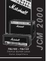
5. Emulated Line Out
This XLR connector provides a superb loudspeaker emulated output
signal, suitable for either connecting into a PA system or for direct
recording, without resorting to using microphones or external DI units.
As stated earlier, by using the “output mute” function, silent recording
can be accomplished, enabling late night project studio sessions to be
carried out with the minimum of stress. This socket can be connected in
a variety of ways. See diagram E.
Each loop has its own ‘loop level’ pushswitch, enabling you to select the
right send and return levels to suit whatever effects system you are using.
With the switch ‘out’, the level within the loop is high (suitable for most
pro rack fx). With the switch ‘in’, the level within the loop is set at a
much lower signal level (suitable more for floor pedals or lesser spec’d
rack units).
Note: The loops are in parallel mode until the mix controls are at 10
when the loop converts to series mode. Also, remember that as the loops
are between the preamp and the power amp, this is NOT the place for
distortion type effects units.
6. Mains Input, Mains Fuse, HT Fuse
The mains input and fuse provide and protect your amplifier with the
incoming electric power, enabling it to operate. Please see specifications
(and amplifier rating) for more details. If in doubt consult your Marshall
dealer. The HT fuse protects your amplifier from an internal fault with
the HT voltage supply. If this blows, it would probably indicate that an
output valve has failed. If this happens, consult your Marshall dealer or
service centre, regarding replacement and service.
3 & 4. Loudspeaker Outputs & Impedence Select
There are three loudspeaker jacks provided on the TSL amps. One is
dedicated to 16 Ohm use only and is marked as such. This is for use
when using either a single 16 Ohm cabinet (Marshall 4x12” of course!)
on the TSL100 head or the internal speakers on the TSL122 combo.
Using this socket negates the use of the other sockets! The other two
WARNING! For your protection and safety, your amplifier must be
serviced by qualified personnel only.
4
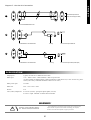
Diagram E - Line Out XLR Connections
3
3
3
2
2
2
2
1
1
1
1
XLR Channel Input On Mixer
(Note: Line Level-Approx OdBV)
2 Core Screened Balanced Mic Lead
B
3
3
2
2
1
1
NC
Unbalanced XLR to Jack Screened Lead
C
3
3
2
2
1
1
Jack Plug
Line Level Jack Input On Mixer Etc.
NC
Unbalanced XLR to Jack Screened Lead
Jack Plug
Low Level Jack Input On Mixer (ie Mic Input)
SPECIFICATION
Output power
(typical) 120 watts at 5% THD into 4/8/16 ohms.
Mains input
117V ~ 60Hz or 230V ~ 50Hz (standard) - others to special order.
(To alter amplifier for different mains voltage specification to that delivered (i.e. 120V to 230V etc), please
contact your country’s Marshall distributor or main service centre.)
Mains power input
375 watts.
Mains fuse
T4A - 117V or T2A - 230V
HT fuse
T1A
Valve (Tube) complement
4 x ECC83 (12AX7) - preamp and phase splitter (inverter).
4 x EL34 - output. Marshall - Svetlana fitted as standard.
WARNING!
!
If the loudspeaker is disconnected a high voltage can be present at these
output terminals. Operation in this manner can damage your amplifier,
therefore ensure that the loudspeaker is properly connected.
WARNING : RISK OF HAZARDOUS ENERGY!
AVIS : ENERGIE ELECTRIQUE DANGEREUSE!
5
ENGLISH
A
3
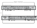
Diagram A - Clean Channel
Front Panel - TSL122 Combo - Clean Channel
JCM 2000 T
4
6
2
GAIN
CLEAN
OD1 / OD2
6
8 2
10
0
INPUT
4
4
8
10
0
VOLUME
OD1 - CRUNCH
OD2 - LEAD
S UPER L EAD
RIPLE
6
2
MID
BOOST
4
6
4
8 2
10
0
TREBLE
OD1
8
10
0
MIDDLE
CLEAN
BASS
MODE
SELECT
3
4
0
4
TREBLE
MIDDLE
4
6
4
6
10
0
10
0
6
4
6
4
4
6
10
0
6
4
8 2
LEAD
OD2
2
VOLUME
6
CRUNCH
6
8 2
10
0
GAIN
4
8
8 2
0
10
TONE
SHIFT
8
2
10
0
10
FX MIX
6
4
6
10
0
10
0
6
4
6
4
10
0
6
4
8 2
8 2
0
REVERB
4
6
8 2
2
BASS
4
10
0
LEAD
CRUNCH
10
0
6
10
0
10
6
4
6
8 2
8 2
10
0
1
5
4
8 2
CLEAN
8 2
PRESENCE
6
10
OFF
8
DEEP
8 2
0
OFF
OUTPUT
MUTE
V.P.R.
8
10
0
7
ON
ON
STANDBY
POWER
TSL 122
POWER AMP
9
8
26
Front Panel - TSL100 Head - Clean Channel
4
T SL 10 0
OFF
OFF
V.P.R.
OUTPUT
MUTE
POWER AMP
ON
ON
POWER
DEEP
4
6
4
6
LEAD
CRUNCH
8 2
4
6
8 2
4
6
8 2
6
2
8
4
6
10
0
10
0
10
0
10
0
10
0
10
0
10
0
10
4
6
4
6
4
6
4
6
4
6
4
6
4
6
4
6
2
8 2
10
8
CLEAN
8 2
10
0
10
0
FX MIX
REVERB
7
6
8 2
10
0
BASS
8 2
0
10
MIDDLE
8
0
10
TREBLE
2
TONE
SHIFT
0
10
VOLUME
MODE
SELECT
10
0
GAIN
4
6
2
OD1
CRUNCH
8 2
JCM 2000 T
OD2
LEAD
8 2
0
PRESENCE
9
4
6
8 2
0
STANDBY
4
6
2
CLEAN
CLEAN
OD1 / OD2
OD1 - CRUNCH
OD2 - LEAD
1
4
6
8 2
10
0
BASS
4
RIPLE
6
8 2
10
0
MIDDLE
5
4
8
0
10
S UPER L EAD
6
2
MID
BOOST
TREBLE
4
4
6
8 2
10
0
8
10
0
VOLUME
GAIN
3
2
INPUT
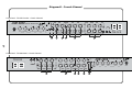
Diagram B - Crunch Channel
Front Panel - TSL122 Combo - Crunch Channel
JCM 2000
4
6
2
CLEAN
OD1 / OD2
6
8 2
10
0
INPUT
4
GAIN
4
8
0
OD1 - CRUNCH
OD2 - LEAD
T RIPLE S UPER L EAD
10
VOLUME
6
2
MID
BOOST
4
6
4
8 2
0
10
TREBLE
10
0
OD1
8
10
0
MIDDLE
CLEAN
BASS
VOLUME
6
0
MODE
SELECT
4
1
MIDDLE
6
4
6
10
0
10
0
6
4
6
4
6
10
0
6
4
8 2
LEAD
OD2
TREBLE
4
4
CRUNCH
6
8 2
GAIN
4
8
8 2
10
0
TONE
SHIFT
2
8
10
0
2
10
0
10
6
4
6
8 2
8 2
10
0
3
6
8 2
2
BASS
4
10
4
FX MIX
6
4
6
0
10
0
4
6
4
LEAD
CRUNCH
10
0
PRESENCE
4
6
10
0
10
6
4
6
8 2
CLEAN
8 2
0
REVERB
4
8 2
8 2
10
0
5
10
OFF
8
DEEP
8 2
0
OFF
V.P.R.
OUTPUT
MUTE
8
10
0
ON
ON
STANDBY
POWER
TSL 122
POWER AMP
6
27
Front Panel - TSL100 Head - Crunch Channel
4
T SL 10 0
OFF
2
OFF
OUTPUT
MUTE
V.P.R.
POWER AMP
ON
ON
POWER
STANDBY
DEEP
4
6
4
6
8 2
4
6
8 2
4
6
LEAD
CRUNCH
4
6
8 2
4
6
8 2
6
2
8
4
6
0
10
0
10
0
10
0
10
0
10
0
10
0
10
0
10
4
6
4
6
4
6
4
6
4
6
4
6
4
6
4
6
2
8 2
0
10
PRESENCE
CLEAN
8 2
10
0
FX MIX
6
0
10
REVERB
8 2
10
0
BASS
8 2
10
0
MIDDLE
5
8
0
10
2
TONE
SHIFT
TREBLE
4
VOLUME
GAIN
3
2
CLEAN
CLEAN
OD1 / OD2
OD1 - CRUNCH
OD2 - LEAD
10
0
4
6
2
CRUNCH
8 2
10
0
MODE
SELECT
LEAD
8 2
JCM 2000 T
OD2
1
4
6
8 2
10
0
BASS
4
RIPLE
6
8 2
0
10
MIDDLE
4
8
0
10
TREBLE
S UPER L EAD
6
2
MID
BOOST
4
6
0
10
8 2
0
10
VOLUME
8
GAIN
INPUT
Diagram C - Lead Channel
Front Panel - TSL122 Combo - Lead Channel
JCM 2000 T
4
6
2
10
GAIN
CLEAN
OD1 / OD2
6
8 2
0
INPUT
4
4
8
0
10
VOLUME
OD1 - CRUNCH
OD2 - LEAD
S UPER L EAD
RIPLE
6
2
MID
BOOST
4
6
4
8 2
0
10
TREBLE
10
0
OD1
8
10
0
MIDDLE
CLEAN
BASS
VOLUME
6
0
MODE
SELECT
4
1
MIDDLE
6
4
6
10
0
10
0
6
4
6
4
6
10
0
6
4
8 2
LEAD
OD2
TREBLE
4
4
CRUNCH
6
8 2
GAIN
4
8
8 2
10
0
TONE
SHIFT
2
8
10
0
10
0
10
6
4
6
8 2
8 2
10
0
3
2
6
8 2
2
BASS
4
10
FX MIX
6
4
6
0
10
0
4
6
4
LEAD
CRUNCH
10
0
4
6
10
0
10
6
4
6
8 2
8 2
10
0
5
4
PRESENCE
8 2
CLEAN
8 2
0
REVERB
4
10
OFF
8
DEEP
8 2
0
OFF
V.P.R.
OUTPUT
MUTE
8
10
0
ON
ON
STANDBY
POWER
TSL 122
POWER AMP
6
28
Front Panel - TSL100 Head - Lead Channel
4
T SL 10 0
OFF
OFF
OUTPUT
MUTE
V.P.R.
POWER AMP
ON
ON
POWER
STANDBY
DEEP
4
6
2
4
6
8 2
4
6
4
6
LEAD
CRUNCH
8 2
4
6
8 2
4
6
8 2
6
2
8
4
6
0
10
0
10
0
10
0
10
0
10
0
10
0
10
0
10
4
6
4
6
4
6
4
6
4
6
4
6
4
6
4
6
2
8 2
0
10
PRESENCE
CLEAN
8 2
10
0
FX MIX
6
0
10
REVERB
8 2
10
0
BASS
8 2
10
0
MIDDLE
5
8
0
10
2
TONE
SHIFT
TREBLE
4
MODE
SELECT
VOLUME
GAIN
3
2
CLEAN
CLEAN
OD1 / OD2
OD1 - CRUNCH
OD2 - LEAD
10
0
4
6
0
10
2
OD1
CRUNCH
8 2
10
0
JCM 2000 T
OD2
LEAD
8 2
1
4
6
0
10
8 2
BASS
RIPLE
4
6
0
10
8 2
MIDDLE
8
TREBLE
S UPER L EAD
4
6
0
10
2
MID
BOOST
4
6
0
10
8 2
VOLUME
8
GAIN
INPUT
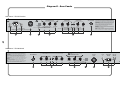
Diagram D - Rear Panels
Rear Panel - TSL122 Combo
!
WARNING!:
RISK OF HAZARDOUS ENERGY!
AVIS!:
ENERGIE ELECTRIQUE DANGEREUSE!
LOUDSPEAKER OUTPUTS
CAUTION!:
EFFECTS LOOP B
EFFECTS LOOP A
FOOT CONTROLLER
TO REDUCE THE RISK OF FIRE REPLACE FUSES WITH THE SAME
TYPE AND RATING ONLY. DISCONNECT SUPPLY CORD BEFORE CHANGING FUSE.
TO REDUCE THE RISK OF ELECTRIC SHOCK DO NOT REMOVE COVER. NO USER
SERVICEABLE PARTS INSIDE. REFER SERVICING TO QUALIFIED SERVICE PERSONNEL.
ATTENTION!:
MAINS FUSE
(T2A - 230V)
(T4A - 120V)
MAINS INPUT
120V ~ 60 Hz
375 Watts
HT FUSE
T1A
8 Ohm
4 Ohm
SELECT
EMULATED
LINE OUT
LOOP
LEVEL
(4 & 8 Ohm PARALLEL JACKS)
16 Ohm ONLY
Note: 16 Ohm Output Jack negates use of others.
REFER TO MANUAL FOR FULL DETAILS. SE REFERER AU MANUEL POUR PLUS DE DETAILS.
4
RETURN
SEND
WARNING!:
SHOCK HAZARD. DO NOT OPEN. TO REDUCE THE RISK OF FIRE
OR ELECTRIC SHOCK DO NOT EXPOSE THIS EQUIPMENT TO RAIN OR MOISTURE.
THIS APPARATUS MUST BE EARTHED.
{
Made in England by:
5
LOOP
LEVEL
SEND
1 - Use EFFECTS LOOP A only as Master Loop (on all three channels)
LOOP MODE 2 - Use EFFECTS LOOP B only for effects on OD channels (CRUNCH & LEAD) only
3 - Use EFFECTS LOOPS A and B for separate effects on CLEAN & OD channels
Marshall Amplification plc, Bletchley, Milton Keynes, England.
6
RETURN
POUR EVITER LES RISQUES D’INCENDIE UTILISER UN FUSIBLE
DE MEME TYPE ET DE MEME CALIBRE. DEBRANCHER AVANT DE REMPLACER LE
FUSIBLE. POUR EVITER LES RISQUES DE DECHARGES ELECTRIQUES, NE PAS
OUVRIR LE COUVERCLE. CET APPAREIL NE COMPORTE AUCUNE PIECE
SUSCEPTIBLE D’ETRE REPAREE PAR VOS SOINS. FAITES TOUJOURS APPEL A
UN TECHNICIEN QUALIFIE POUR TOUTE REPARATION.
3
AVIS!:
RISQUE DE CHOC ELECTRIQUE. NE PAS OUVRIR. POUR EVITER LES
RISQUES D’INCENDIE ET DE DECHARGES ELECTRIQUES, N’EXPOSEZ JAMAIS CET
APPAREIL A L’HUMIDITE OU A LA PLUIE. CONNECTER CET APPAREIL A LA TERRE.
2
1
29
Rear Panel - TSL100 Head
1 - Use EFFECTS LOOP A only as Master Loop (on all three channels)
LOOP MODE 2 - Use EFFECTS LOOP B only for effects on OD channels (CRUNCH & LEAD) only
3 - Use EFFECTS LOOPS A and B for separate effects on CLEAN & OD channels
CAUTION!:
{
TO REDUCE THE RISK OF FIRE REPLACE FUSES WITH THE SAME TYPE
AND RATING ONLY. DISCONNECT SUPPLY CORD BEFORE CHANGING FUSE.
TO REDUCE THE RISK OF ELECTRIC SHOCK DO NOT REMOVE COVER. NO USER
SERVICEABLE PARTS INSIDE. REFER SERVICING TO QUALIFIED SERVICE PERSONNEL.
ATTENTION!:
POUR EVITER LES RISQUES D’INCENDIE UTILISER UN FUSIBLE DE
MEME TYPE ET DE MEME CALIBRE. DEBRANCHER AVANT DE REMPLACER LE FUSIBLE.
POUR EVITER LES RISQUES DE DECHARGES ELECTRIQUES, NE PAS OUVRIR LE
COUVERCLE. CET APPAREIL NE COMPORTE AUCUNE PIECE SUSCEPTIBLE D’ETRE
REPAREE PAR VOS SOINS. FAITES TOUJOURS APPEL A UN TECHNICIEN QUALIFIE POUR
TOUTE REPARATION.
FOOT CONTROLLER
EFFECTS LOOP A
EFFECTS LOOP B
!
Made in England by:
WARNING!: RISK OF HAZARDOUS ENERGY!
AVIS!: ENERGIE ELECTRIQUE DANGEREUSE!
Marshall Amplification plc, Bletchley, Milton Keynes, England.
LOUDSPEAKER OUTPUTS
EMULATED
LINE OUT
HT FUSE
MAINS INPUT
MAINS FUSE
T1A
120V ~ 60 Hz
375 Watts
(T2A - 230V)
(T4A - 120V)
WARNING!:
SHOCK HAZARD. DO NOT OPEN. TO REDUCE THE RISK OF FIRE OR
ELECTRIC SHOCK DO NOT EXPOSE THIS EQUIPMENT TO RAIN OR MOISTURE.
THIS APPARATUS MUST BE EARTHED.
LOOP
LEVEL
SEND
AVIS!:
RISQUE DE CHOC ELECTRIQUE. NE PAS OUVRIR. POUR EVITER LES RISQUES
D’INCENDIE ET DE DECHARGES ELECTRIQUES, N’EXPOSEZ JAMAIS CET APPAREIL A
L’HUMIDITE OU A LA PLUIE. CONNECTER CET APPAREIL A LA TERRE.
LOOP
LEVEL
RETURN
SEND
RETURN
16 Ohm ONLY
(4 & 8 Ohm PARALLEL JACKS)
4 Ohm
8 Ohm
SELECT
Note: 16 Ohm Output Jack negates use of others.
REFER TO MANUAL FOR FULL DETAILS. SE REFERER AU MANUEL POUR PLUS DE DETAILS.
1
2
3
4
5
6