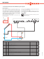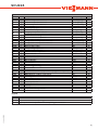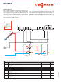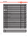
1
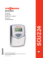
SCU224
1. Installation
1.1Mounting
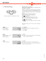
WARNING! Electric shock!
Opening the housing will expose
live parts!
ÎÎ Switch off power supply and disconnect the device from power supply
before opening the housing!
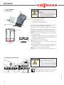
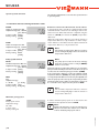
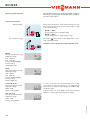
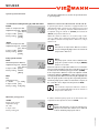
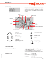
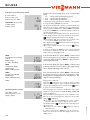
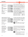
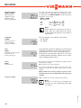
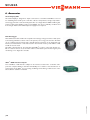
display
push button
cover
cable conduits with strain
relief
fuse 4A
upper fastening
.
„
lower fastening
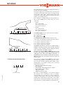
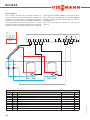
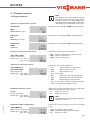
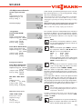
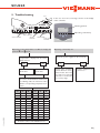
1.2Electrical connection
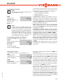
fuse
The unit must only be installed
•• in a dry interior location
•• in a non-hazardous location
•• away from electromagnetic fields
The controller must additionally be supplied from a doublepole switch with contact gap of at least 0.12".
Route sensor cables and power supply cables separately.
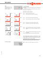
ÎÎ Unscrew the cross-head screw from the cover and
remove it along with the cover from the housing
ÎÎ Mark the upper fastening point on the wall and drill
ÎÎ Fasten the enclosed wall plug and screw leaving the
head protruding
ÎÎ Hang the housing from the upper fastening point and
mark the lower fastening point through the hole in the
terminal box (centers 5.1")
ÎÎ Drill and insert the lower wall plug
ÎÎ Fasten the housing to the wall with lower fastening
screw and tighten
ÎÎ Complete wiring connections in accordance with terminal allocations, see chap. 1.2 “Electrical connection”
ÎÎ Place the cover back onto the housing
ÎÎ Fasten the cover by means of the cross-head screw
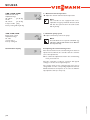
ATTENTION! ESD damage!
Electrostatic discharge can lead to damage to electronic components!
ÎÎ Take care to discharge properly
before touching the inside of the
device. To do so, touch a grounded
surface such as a radiator or tap!
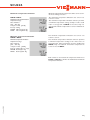
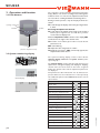
Note:
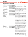
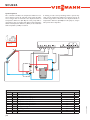
VBus®
sensor terminal
ground terminal
load terminals
The minimum pump speed must be set to 100 %
when auxiliary relays or valves are connected.
© Viessmann 5443203
power supply terminals
|4