1
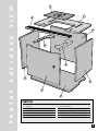
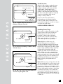
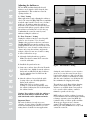
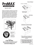
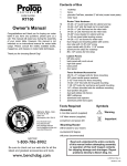
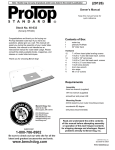
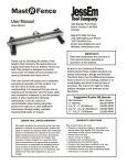
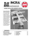
(20253) I N S T R U C T I O N S Stock No. 40-001 Congratulations on your Bench Dog ProTop Contractor’s Table purchase! Follow these simple assembly instructions to construct your quality router table and cabinet. Note: Please read these instructions completely before starting to assemble your ProTop Contractor’s Table. Familiarity with the process will make the steps easier to understand. Please follow all steps carefully. RTD10000485AC V I E W 7 1 8 P R O T O P E X P L O D E D 6 10 9 4 5 3 2 PARTS LIST 1 2 3 4 5 6 Router Top Base Panel Door Left Side Panel Right Side Panel Back Panel 4XDQWLW\ 1 1 1 1 1 1 7 8 9 10 11 12 Router Insert Plate 24" Miter Track Right Insert Bracket Left Insert Bracket Insert Plate Template (Not Shown) Decals (Not Shown) 4XDQWLW\ 1 1 1 1 1 2 2 L I S T 15 21 13 34 22 18 P R O T O P H A R D W A R E 25 19 14 17 29 28 30 16 20 24 26 27 23 PARTS LIST 13 14 15 16 17 18 19 20 21 22 23 24 1/4-28 1/4-20 1/4-20 1/4-20 1/4-20 1/4-20 1/4-20 1/4-20 1/4-20 1/4-20 1/4-20 1/4-20 4XDQWLW\ x 1/2" Set-Socket Screw 11 x 3/4" Hex Head Bolt 4 x 11⁄4" Button Head Socket Cap screw 4 x 5/8" Flat Head Socket Cap Screw 2 x 1" Flat Head Phillips Screw 2 x 11⁄4" Flat Head Socket Cap Screw 6 x 13⁄4" Flat Head Socket Cap Screw 12 x 50mm (2") Round Head Bolt 4 x 3/4" Socket Head Cap Screw 8 T-Nut (Joint Connector) 4 Cross Dowel 18 Nylon Insert Lock Nut 10 25 26 27 28 29 30 31 32 33 34 35 36 4XDQWLW\ 1/4-20 Hex Nut 8 8-32 x 1/2" Flat Head Phillips Screws 3 10-24 x 5/8" Flat Head Phillips Screws 3 6 x 20 mm, Flat Head Phillips Screws 3 5/16-18 x 3/4", Flat Head Phillips Screws 3 10-32 x 5/8", Flat Head Phillips Screws 3 3/16" Hex Wrench (Not Shown) 1 5/32" Hex Wrench (Not Shown) 1 1/8" Hex Wrench (Not Shown) 1 Rubber Feet 4 Self Closing Euro Style Hinge (Not Shown) 2 Hinge Mounting Plate (Not Shown) 2 3 V I E W E X P L O D E D F E N C E 1 8 10 6 4 7 5 9 2 7 9 3 5 1 2 8 10 9 Table Top Follow this diagram to attach the fence to the table. PROFENCE PARTS LIST 1 2 3 4 5 6 7 8 9 10 4XDQWLW\ Aluminum Fence Adjustable MDF Fence Faces Bit Safety Guard Dust Port 3/8-16 T-Knobs 5/16-18 x 11⁄4" T-Bolts 1" Round Knobs Knob Spacer 3/8-16 x 21⁄2" Carriage Bolts 3/8" Nylon Washer 1 2 1 1 2 6 6 2 2 2 4 12 5 C A B I N E T A S S E M B L Y 3 35 Fig. 1 Fig. 2 1. Press the hinge “cups” (35) into the large bore in the door (3). Fig 1. With a Phillips screwdriver, tighten the integral hinge cams clockwise approximately 1/4 turn. Do not over tighten the cams. 4 2. Attach the two decals (12) to the side panels. The decals go on the outside of the left and right side panels (4 and 5). The right side panel decal is positioned near the front curved edge, as shown in Fig 2. In this photo the person is installing the decal on the left side panel, about two inches from the back edge. If you find it easier, attach the decals AFTER your router table is fully assembled. 36 Fig. 3 5 6 4 Fig. 4 2 32 34 Fig. 5 2 3. Attach the two hinge mounting plates (36) to the left side panel (4). Carefully study the orientation in Fig. 3. The hinge mounting plates resemble a cross. Locate the top of the cross nearest the curved front edge of the left side panel, as shown. On the bottom of the cross you will find the hinge release lever. All cross dowel holes are located inside the cabinet. 4. Attach side panels to the back panel (6). The back panel has two notches that identify the top of the panel, as shown in Fig 4. The left panel has the hinges. Align the two holes in side panels with the corresponding holes in the back panel. Use 1/4-20 x 2" round head bolts (20) and 1/4-20 cross dowels (23). The cross dowels go in the back panel. Tighten with the included 5/32" hex wrench (32). Repeat this step for the right panel. Do not fully tighten the bolts at this time. 5. Attach the four rubber feet (34) to base panel (2). Fig 5. Insert the “T” nuts (22) into the four large holes in the base panel (2). Locate the head of the “T” nut on the top side of the base panel. The bottom of the base panel has countersink holes, the top does not. Insert a 1/4-20 x 3/4" hex head bolt (14) through the rubber feet, and thread into “T” nut, as shown. Tighten using the 3/16" hex wrench (31) and a 7/16" socket. Do not overtighten. 6. Attach base panel to cabinet assembly. Flip the cabinet assembly upside down, as shown in Fig 6. Use the 1/4-20 x 13⁄4" flat head socket cap screws (19) and 1/4-20 cross dowels (23). Tighten securely. Flip the cabinet assembly right side up when done. Fig. 6 5 10 A S S E M B L Y 10 9 10 Fig. 7 Fig. 8 7. Attach insert brackets (9 and 10) to routertop using four 1/4-20 x 11⁄4" flat head socket cap screws (18) and nylon nuts (26). Position insert brackets as shown in Fig 7. Be sure to mount the brackets to the underside of the routertop (Fig 7 inset). The routertop surface has countersinks, the underside does not. Do not fully tighten the bolts. 8. Fully thread a 1/4" hex nut (25)on each of the eight 1/4-20 x 3/4" socket head cap screws (21). Install these bolt assemblies into the eight leveling holes in the insert brackets(9 and 10). Fig. 8. DO NOT use the two insert plate attachment holes. These holes have protruding round nuts on the underside of the insert brackets. You will adjust these leveling screws in step 14. Fig. 9 9. Attach routertop to cabinet asssembly using 1/4-20 x 13⁄4" flat head socket cap screws (19) and 1/4-20 cross dowels (23). Do not fully tighten at this time. C A B I N E T 8 Fig. 10 10. Connect insert brackets to the back panel. Attach using 1/4-20 x 11⁄4" button head screws (15) and 1/4" nylon insert lock nuts (24), as shown in Fig. 9. Locate the nuts to the inside of the cabinet. Do not fully tighten at this time. 11. Attach the miter track to routertop. Use two 1/4-20 x 5/8" flat head socket cap screws (16) and 1/4" nylon insert lock nuts (24) to fasten the miter track to the insert brackets. Use two 1/4-20 x 11⁄4" flat head socket cap screws(18) and 1/4-20 cross dowels (23) to fasten the miter track to the cabinet side panels (Fig 10). Eliminate any gap between the miter track and routertop before tightening the bolts. Fig. 11 12. Fully tighten all bolts and screws. Correct any misalignments at this time. Fig. 11. 13. Adjust miter gauge track to fit your standard miter gauge (Not included). First test fit your miter gauge into the track. If it’s too tight, squeeze the gib against the front wall of the miter track with a pair of Channel Locks, using a shop towel to prevent marring. Next, install the eleven 1/4-28 x 1/2" set screws (13). Fig 12. Tightening the screws will deflect the gib into your miter gauge. Tighten all screws uniformly and gradually until the desired fit is achieved. Fig. 12 6 C A B I N E T A S S E M B L Y 37 36 Fig. 13 Fig. 14 14. Install the insert plate into the routertop. Adjust leveling screws until the plate is flush with routertop. To tighten, hold the socket head cap screw with the 3/16" hex wrench (31), and use your 7/16" open end wrench to tighten the nuts, as shown in Fig 13. Note: it may be necessary to fine tune the adjustment after installing router. Fig. 15 15. Attach door. Clip on door by “hooking” front of hinge onto hinge mounting plate (37) first. Fig 14. Then push on back edge of hinge until it locks into place. If door does not clip on, check hinge mounting plates for proper installation. To remove door, push down on release levers. 16. Attach fence (see page 4 for exploded view). For more workpiece support, the fence can be reversed and positioned on the “front” of router table as shown in Fig. 15. Install the bolts from inside the cabinet. Fig. 16 18. Attach the bit guard to fence. Fig. 16. Pre-assemble the guard with the two 5/16-18 x 11⁄4" hex bolts (6) and two knobs (7). Slide both bolt heads into the fence’s T-slot to attach to fence. 19. Mount router to the insert plate. This insert plate is predrilled to fit most popular routers, and comes with proper mounting screws for these routers. Fig. 17. In some cases, you must drill your own holes and purchase your own mounting screws. Please refer to the included template (11) to complete this step. Fig. 17 Fig. 18 20. Install router and plate into the routertop as shown in Fig. 18. Re-adjust the insert plate flush if necessary (see step 13). Install the two 1/4-20 x 1" flat head phillips screws (17) into the two corners of the insert plate. These screws prevent side-to-side movement and keep the insert plate firmly seated, preventing excessive vibration. Do not overtighten as this could damage the insert plate. 7 T I P S Securing the Router Table The base has rubber feet to reduce vibrations and slippage of the base on a smooth suface. For permanent mounting, the base can be bolted through the rubber feet for a workstation or bench. For a secure yet portable mounting, the base is equipped with two special recesses that accept scrap 2 x 4 dimensional lumber. Fasten the scrap 2 x 4 pieces to your bench using clamps or screws (Fig. 19). O P E R A T I O N A L Fig. 19 Using Your Miter Gauge The miter track has two slots: an accessory T-slot and a T-bar compatible miter gauge slot. The accessory T-slot is the narrower of the two. It accepts 1/4" hex bolts for attaching Feather-Loc featherboards (see Bench Dog Tools accessories) and other fence accessories like Panel-Loc and Power-Loc. The miter gauge slot is used in conjunction with a miter gauge, and fits standard 3/8" x 3/4" miter bars (with or without the T-bar). The miter gauge is not included. To adjust fence perpendicular to miter gauge, set miter gauge to 90° and place in slot (make sure miter track is adjusted, see step 13). Loosen the fence’s lock knobs and align the miter gauge to fence using a square, as shown in Fig. 20. Dust Collection The integral dust collection port (Fig. 21) is designed to accept a standard 21⁄2" fitting, typical on most shop vacs. Most of these fittings actually measure 21⁄4" (outside diameter). Bench Dog Tools recommends 21⁄2" hose, or larger, because it is more effective at evacuating dust and chips, and provides proper air flow over the router motor. Any hose larger or smaller than 21⁄2" requires an adapter you must provide. If additional dust collection is needed, a dust port can be added to your cabinet or motor area. DO NOT USE YOUR ROUTER TABLE WITHOUT DUST COLLECTION! Fig. 20 Temperature Regulation To prevent router overheating, periodically open the cabinet door during use and never let dust and debris collect inside the cabinet. Always use a vacuum at the fence-mounted dust port. For extended operation you must install a dust port in the cabinet or remove the door during operation. Fig. 21 8 Feed Direction Router top (top view) Router bit rotation Fence Workpiece F E N C E T R A P S Proper feed direction Fig. 22 - A typical setup. Here, the fence is partially covering the router bit. Always feed the workpiece against the cutter rotation, as shown in Fig. 22. Feeding the workpiece with the cutter rotation is called “climb cutting”. Climb cutting is very dangerous, because the cutter will grab the workpiece and thrust it the same direction as the cutter rotation. Even small router bits will overpower your ability to hold onto the workpiece during a climb cut. Do not use this router table until you understand proper feed direction and bit rotation. If climb cutting is still unclear, ask your retailer for help, give us a call, or reference a book on router table usage. CAUTION: NEVER CLIMB CUT! Avoiding Fence Traps Fence Workpiece Bit rotation Proper feed direction Fig. 23 - A classic trap resulting in a climb cut. Always avoid this set-up! Fence Workpiece Bit rotation Proper feed direction Fig. 24 - Not a trap as long as the router bit does not cut all the way through the stock. Fence traps occur when the work piece is fully “trapped” between the router bit and fence. Fence traps pose two real concerns: the possibility of climb feeding, and human exposure to the router bit. As stated earlier, climb cutting should be avoided as loss of control of the operation is a possibility! Figure 23 shows a classic trap to be avoided. What appears as a normal feed direction (working from right to left) is wrong, and will instead produce a climb cut. Because the work piece is trapped it can easily be pulled from one’s grip and thrown with great velocity. Feeding the stock from left to right will eliminate the climb cut but not the danger. It will be difficult to keep the stock tight against the fence as the bit’s rotation will thrust the stock away from the fence. Also, your body will be dangerously exposed to the spinning router bit. The bit guard will not protect you against flying stock, nor guard against this level of exposure. Figure 24 is not a trap, as long as the router bit cuts only partially into the stock. In other words, the router bit must not completely cut through the workpiece. In this cut, the bit will grab and push the stock toward the fence. This is good, as the fence will control the workpiece better than your hands. Typical dado cuts resemble this set-up, and are commonly performed on router tables. If the dado is to be widened with two (or more) passes, be careful not to set a classic trap or climb cut. 9 A D J U S T M E N T Adjusting the Subfences The two MDF (medium density fiberboard) subfences are designed to slide along the fence approximately 2". This results in a router bit opening from 0 to 4". A. “Close” Setting Many applications require adjusting the subfences close to the router bit. (Fig. 25) This accomplishes nearly the same benefits of a true “zero clearance” setting (see B) without cutting the subfences. Before the router is turned on, and after the fence and router bit height are properly adjusted, slide the subfences toward the bit to reduce the gap. Confirm that the router bit can freely rotate without touching the subfences! B. “Zero Clearance” Setting Cutting the subfences into the router bit profile produces “zero clearance”. Zero clearance eliminates the gap between the fence and router bit. (Fig. 26) This prevents the workpiece from getting pulled into the fence just before the router bit. Moreover, a zero clearance setting achieves a cleaner cut because the subfence supports the workpiece fibers. If a true zero clearance setting is desired, follow these steps: MDF subfence MDF subfence Fig. 25 - “Close” Setting MDF subfence MDF subfence 1. Adjust the bit height and fence position. Note: The subfences must NOT contact the router bit at this time. 2. Install the bit guard and secure. S U B F E N C E Fig. 26 - “Zero Clearance” Setting 3. Start router, and use dust collection. From the back of the fence, slightly loosen the subfence knobs and carefully slide the infeed subfence into the spinning router bit. Hold onto the subfence knobs. 4. After the subfence has reached the guide bearing of the router bit, fully tighten the knobs on the subfence. Note: If the bit does not have a guide bearing (i.e. vertical raised panel bits), slide the subfence half-way into the bit, then tighten the subfence knobs. Caution: Never adjust or slide the subfences from the front! Always work from the back with both hands on the adjustment knobs. Important Notes: The outfeed subfence is rarely set to zero clearance, because doing so has little performance benefit and can damage the subfence. A “close” setting is more desirable for most applications. Setting the outfeed subfence to zero requires great care because the router bit can cause a portion of the subfence to chip or break. If an outfeed zero clearance is absolutely necessary, slide the outfeed subfence very slowly into the bit to minimize the chipping and tearing. The subfences can be flipped when changing profiles or bit heights. New, replacement subfences are available when a new profile is to be created or if the subfence cannot be trimmed to provide a fresh edge. MDF works very well as a subfence because it is softer than most woods and is much less likely to damage expensive router bits. MDF also retains the shape of delicate profiles and thus allows proper support for zero clearance settings. When adjusting the fence, ensure that no part of the aluminum fence body could contact the router bit. 10 S A F E T Y Important Safety Points Before operating your router table please read this manual thoroughly. Safety and use tips are contained in the manual. This page is not the sole source of safety information. Retain the manual for future reference. Refer to your router owner’s manual for safety instructions regarding use of that tool. This manual is not an instruction book on how to do woodworking with a power tool. We encourage all woodworkers to continually seek improvement in their woodworking skills, regardless of their craftsmanship or years of experience. The router table, fence and accessories must only be used for their intended purpose: woodworking via normal routing operations. “Normal operations” means basic shaping of wood in conditions where grounded electricity, sharp tools, dust, and rapidly spinning parts can be used or encountered safely. The following instructions elaborate on this concept. 1. 2. 3. 4. 5. 6. 7. & 8. 9. 10. W A R R A N T Y 11. 12. 13. 14. 15. Do not use your router table as a step or seat. The top and cabinet must be properly secured, and must be level before use. Inspect your table and base for damage and levelness prior to each use. Keep work area clean, dry and well lit. The hardware affixing the insert to the routertop must be installed for safe use. Tighten insert hold-down screws before each use. Safe operation requires a router table fence, bit guard, dust collection system, starting pin or fulcrum, and speed reducer for large diameter bits. We recommend reducing router speed for 1” or larger diameter bits. Consult your bit manufacturer for the exact speed. Use the right tool for the job. Do not force a tool or attachment to do a job for which it was not designed. Secure your work with a featherboard, clamps, or a vice when appropriate. The use of inappropriate accessories may cause injury. Wear safety glasses, dust mask, face shield and ear protection. This is not an exhaustive list. Every-day eye glasses do not substitute for safety glasses. Do not wear gloves or jewelry while using a power tool and ProMAX. Maintain your equipment and its accessories in good working condition. Look for wear, poor alignment of moving parts, binding of moving parts, breakage, poor mounting, or other conditions that may affect operation and safety. Repair or replace any damaged parts. Disconnect the power before moving, adjusting, or repairing parts, or otherwise maintaining your router table and any accessories you may be using. Keep children, pets, and those who may disregard safety away from work area, cords, sockets and tools. Wear snug fitting clothes and keep long hair back to avoid catching in moving parts. Do not overreach. Maintain balanced footing and stance. Stay alert. Use common sense. LIMITED TWO-YEAR WARRANTY We make every effort to assure that our products meet quality and durability standards, and warrant to the original retail purchaser that this product is free from defects in materials and workmanship for two years. Remedy shall be limited to Bench Dog’s choice of repair, replacement or refund. This warranty does not provide remedy for consequential economic loss. This is a limited two-year warranty. It requires the purchaser to contact Bench Dog in writing within 30 days of discovering the defect. Warranty does not apply to defects due directly or indirectly to misuse, abuse, negligence or accidents, repairs or alterations, or due to lack of maintenance. It excludes components and parts not manufactured by Bench Dog, defects caused by failure to provide a suitable installation environment, and damage caused by use for purposes other than those for which the product was designed. Bench Dog, Inc. reserves the right to make product changes without notice and without obligation to make these changes on products previously sold. It excludes warranties of fitness for a particular purpose. If the product is defective, we reserve the right to fix it, replace it, or refund the cost of the product to you. Typically, this results in a refund. All claims are limited to the two-year claims period. We must receive the product before a credit or refund will be issued. The warranty language on the product or in the product’s manual may contain additional limitations, which govern. If you wish to return something, call the dealer where you purchased the product. If you wish to return something purchased from Bench Dog directly, call 1-800-786-8902 to receive an RMA number. Upon receipt and inspection of the goods, a credit or replacement will be issued for defective products. Return of nondefective items to Bench Dog are subject to a 7% restocking charge. This is necessary due to the cost of checking, repackaging, and inventorying the stock. BENCH DOG DISCLAIMS AND BUYER EXPRESSLY WAIVES ANY AND ALL WARRANTIES, EXPRESS OR IMPLIED, INCLUDING BUT NOT LIMITED TO, IMPLIED CONDITIONS OF FITNESS FOR A PARTICULAR PURPOSE, MERCHANTABILITY, OR ANY OTHER MATTER. 5HY %HQFK'RJ7RROV 11