1
EBA-03 Bill Validator
Bill Acceptor Series
Section 4
4 CALIBRATION
Connecting a PC for Calibration
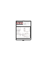
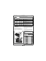
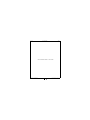
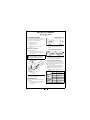
Figure 4-1 illustrates the required equipment inter-connection necessary to properly calibrate the EBA-03
unit.
Figure 4-1 EBA-03 Test Setup
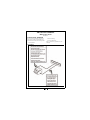
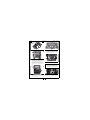
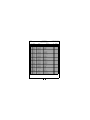
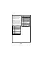
Figure 4-2 illustrates the required tools necessary to properly calibrate the EBA-03 unit.
Figure 4-2 EBA-03 Test Tool Requirements
Installing the Calibration Software
VM-450 and EBA-03 DIP Switch
Settings
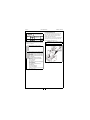
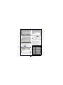
1. Place the EBA-03 calibration software CD
into your CD drive. Wait a few seconds, and
the first screen shown in Figure 4-4 will
appear.
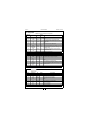
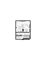
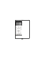
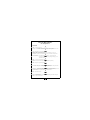
Figure 4-3 illustrates the VM-450 and the EBA-03
proper test DIP Switch settings.
2. Once the files are copied, the second screen
shown in Figure 4-5 will appear.
Figure 4-3 VM-450 and EBA-03 DIP Switches
When power is applied to the VM-450, the Red
and Green LEDs on the EBA-03 will light. This
means the unit is in Standby Mode. Tests and
adjustments are performed in this mode.
If the LEDs fail to light, recheck the DIP Switch
settings. Turn power to the VM-450 OFF, then turn
it back ON. If the LEDs still do not light, check the
ROM and CPU Board’s integrity.
JCM Part No. 960-000058R_Rev. 2
Figure 4-4 Initial Software Install Screen
13
© 2008, JCM-American Corporation