1
Serial Peripheral Interface (SPI)
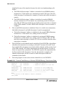
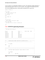
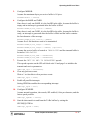
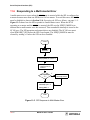
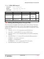
The following example shows the steps required to initialize the SPI as a slave. The
assumptions underlying this example are:
■
IMM is a pointer to the MSC8101 registers in the PowerPC system bus and
PowerPC local bus address spaces.
■
SPIPRAM is a pointer to the SPI parameter RAM.
■
RxTxBD is a pointer to the buffer descriptors RxBD and TxBD.
■
One RxBD and one TxBD are used.
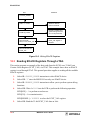
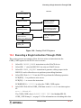
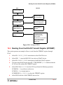
The steps in initializing the SPI as a slave are as follows:
1.
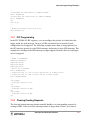
Configure Port D for SPI.
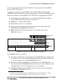
In the slave mode, SPISEL, SPIMOSI, SPIMISO, and SPICLK are enabled. The
PPARD and PDIRD and PSORD are configured as follows:
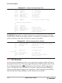
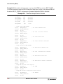
IMM->io_regs[PORT_D].ppar = 0x0000F000;
IMM->io_regs[PORT_D].pdir = 0x00000000;
IMM->io_regs[PORT_D].psor = 0x0000F000;
2.
Assign a pointer to the SPI Parameter RAM.
At location IMM+0x89FC, SPI_BASE points to the SPI Parameter RAM area
which can be placed at any 64-byte aligned address in the dual-port RAM’s
general-purpose area (Banks 1-8 located at IMM+0x0 through IMM+0x3FFF).
In this example, assume that the SPI Parameter RAM area is located in Bank 8 at
IMM+0x3800.
IMM->pram.standard.spi[0] = 0x38;
IMM->pram.standard.spi[1] = 0x00;
3.
Configure RBASE and TBASE.
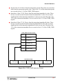
Assume that there is one RxBD followed by one TxBD at the beginning of the
dual-port RAM and the RxBD starts at IMM+0. Since each buffer descriptor is
8-bytes, the TxBD starts at IMM+8.
SPIPRAM->rbase = 0x0000;
SPIPRAM->tbase = 0x0008;
4.
Configure RFCR and TFCR.
Assume big-endian byte ordering is used.
SPIRAM->rfcr = 0x10;
SPIRAM->tfcr = 0x10;
11-10
MSC8101 User’s Guide