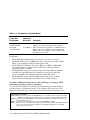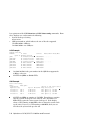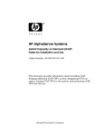
1
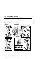
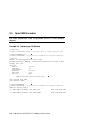
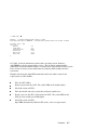
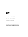
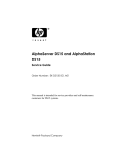
AlphaServer GS160/320
CPU Online Addition and Removal
Order Number: EK-GSHPG-RM. A01
This document is for system owners and service providers of
AlphaServer 160/320 systems. It describes how to add and
replace CPU modules in a running system and restrictions
related to that servicing.
Compaq Computer Corporation
July 2001
© 2001 Compaq Computer Corporation.
Compaq, the Compaq logo, AlphaServer, and StorageWorks Registered in U.S. Patent and Trademark
Office. OpenVMS and Tru64 are trademarks of Compaq Information Technologies Group, L.P. in the
United States and other countries.
Portions of the software are © copyright Cimetrics Technology. UNIX is a trademark of The Open
Group in the United States and other countries. All other product names mentioned herein may be
trademarks of their respective companies.
Compaq shall not be liable for technical or editorial errors or omissions contained herein. The
information in this document is provided “as is” without warranty of any kind and is subject to change
without notice. The warranties for Compaq products are set forth in the express limited warranty
statements accompanying such products. Nothing herein should be construed as an additional
warranty.
Chapter 1
Overview
The AlphaServer GS160/320 systems support the removal and addition of CPU
modules while the system is powered on and applications are running. This
chapter provides background information so that one can safely service these
machines and understand requirements about which CPUs can go where.
Chapter 2 outlines the procedures and gives specific operating system examples
of replacing a CPU in a running system.
Questions and Answers
What is the advantage of online service?
These systems were designed to provide high availability, so that the operating
systems can continue to run while parts of the machine can be serviced or
upgraded. Some components can be replaced while the operating system
continues to run and power is present in the area where the component is to be
replaced. In other cases power is removed from the area that is to be serviced,
but other parts of the system remain powered on.
The online addition and removal of CPU modules means that a faulty CPU
module can be replaced while the operating system and applications continue to
run. In addition, the CPU capacity can be expanded without any downtime.
What is required for online service of CPUs?
The system must be running versions of firmware, operating systems, and
WEBES that support this function. See Table 1–1. Also, with Tru64 UNIX
Compaq Analyze must be running in auto analysis mode to support indictment
of faulty CPUs (Compaq Analyze is one of the WEBES (Web-Based Enterprise
Services) tools. OpenVMS does not support indictment.
Table 1–1 Minimum Versions Required
Tru64 UNIX
OpenVMS
SCM & SRM
WEBES
V5.1A
V7.3 *
V6.0
V4.0
*Remove and replace only.
Overview
1-1
Who may service these systems?
Only those with appropriate technical training and experience should attempt
to service these systems.
What precautions are to be taken?
Table 1–2 lists the various power and mechanical hazards in the system.
Because these systems use a great deal of power, caution must be exercised
when servicing them. Remove all jewelry when working on the systems.
The use of ESD straps is required. Wrist straps are located on the front and
rear doors of system cabinet 1 and on the rear door of the power cabinet.
Table 1–2 Hazards and Safety Features
Hazard
Risks
Safety Features
Exposed Areas
AC power
Flashing metal
Shock
Death
AC only in the power cabinet
AC loads fully enclosed
Securely mated wiring system
None
48 VDC
power
Flashing metal
Welding of jewelry
➨ heat
Securely mated wiring system
48V isolated from cabinets
Covers
Current limit
QBB backplane
H-switch backplane
CPU module
Power modules
Low
voltage
power
Flashing metal
Welding of jewelry
➨ heat
Short circuit protection
Current limit
QBB backplane
H-switch backplane
Logic modules
Power modules
System
blowers
Severe cuts
Loss of fingers
Grill
Exposed only when
lower system box out
PCI
enclosure
Low voltage power
hazard
Battery on
standard I/O
AC loads fully enclosed
Interlock
Under power supply
connector on the
backplane
1-2 AlphaServer GS160/320 CPU Addition and Removal
What do I need to know about the system clock, CPU variants,
and the system box QBBs?
Early GS160/320 systems used the B4125 CPU module, which supported a
4-Mbyte backup cache. The QBBs in the early system boxes (BA51A-AA)
supported the 4-Mbyte B-cache. With the introduction of the B4166 CPU
modules which support an 8-Mbyte B-cache comes a system box (BA51A-BA)
with QBBs that support the larger B-cache. Furthermore, the CPU derives its
operating clock speed from the system clock, so you need to know the setting of
the system clock. Most of these components can coexist in the same system.
But for optimum performance the B4166 CPUs should be in a system box with
QBBs that support the 8-Mbyte B-cache and in a system with the 9.0 ns clock
setting.
Table 1–3 compares the B4125 and B4166 CPUs, and Table 1–4 compares the
system boxes.
Table 1–3 Comparison of CPUs
CPU Part
Number
B-cache
Size
Speed
in MHz
B4125
4 Mbytes
731
The B4125 must operate at this speed and requires
the system clock to run at 9.6 ns.
B4166
4 or 8
Mbytes
1001
The B4166 runs at this speed and uses all its available B-cache when all CPUs in the system are B4166,
the clock runs at 9.0 ns, and the CPUs are in a system
box with duplicate tag support of the 8-MB cache. If
the system box duplicate tag supports only 4-MB
cache, then only 4 of the 8 Mbytes of B-cache on the
CPU are used.
4 or 8
Mbytes
940
The B4166 runs at this speed and uses all its available B-cache when all CPUs in the QBB are B4166,
and the clock runs at 9.6 ns. This occurs because the
system clock is run at 9.6 ns. If the system box duplicate tag supports only 4-MB cache, then only 4 of
the 8 Mbytes of B-cache on the CPU are used.
Uses 4 of
its 8 Mbyte
B-cache
731
The B4166 runs at this speed and uses 4 Mbytes of its
B-cache when both CPU variants (B4125 and B4166)
are placed in the same QBB and the clock runs at 9.6
ns.
Comments
Overview
1-3
Table 1–4 Comparison of System Boxes
System Box
Part Number
Cache Size
Supported
by the Box
Comments
BA51A-AA
(54-25043-01/02)
4 Mbytes
Though the B4166 CPU has an 8-Mbyte B-cache, only
4 Mbytes are used when placed in this backplane.
BA51A-BA
(54-25045-01/02)
4 or 8 Mbytes
When all CPUs in this backplane are B4166, all use 8
Mbytes of B-cache. If CPUs are mixed, B4125 and
B4166 on the same backplane, all are configured for
the 4-Mbyte B-cache size.
In summary:
•
•
•
•
•
The BA51A-AA and BA51A-BA system boxes can coexist in a system.
The B4125 CPUs run at 731 MHz and require a 9.6 ns system clock. B4125
CPUs are not supported with the 9.0 ns system clock.
B4125 CPUs have 4 Mbytes of B-cache. When in a QBB in a BA51A-BA
system box, firmware configures these CPUs to be consistent with the
amount of B-cache available.
The B4166 CPU can operate at different speeds and use different amounts
of its B-cache depending upon the system box it is in, the system clock
speed, and whether it is configured with the B4125 CPU or not.
The B4166 CPU requires that the SRM console firmware be at V6.0 or
higher and that the microprocessor firmware be at V6.0 or higher.
Are there additional restrictions when adding or changing CPUs
when the operating system is running?
Yes, because the firmware recorded what speed modules were in which slots at
system startup, you should not change the speed of the CPU in that slot. The
firmware will not take note of the change in the CPU until the next power cycle.*
Terminology clarification:
Power cycle: Occurs when the SRM or SCM power off console command is issued, followed by the SRM
power on command. Power is turned off and on, testing begins, and the SRM prompt returns.
Initialize: Occurs when the SRM initialize command is issued; it causes the I/O adapters to initialize. The
system must then be booted.
Reboot: Occurs at the operating system level; causes an SRM initialize command.
Reset:
Occurs when the control panel Reset button is pushed or when the SRM or SCM reset command is
issued. This causes a system-level hardware reset, initiating testing and return of the SRM
prompt. Power is not turned off.
1-4 AlphaServer GS160/320 CPU Addition and Removal
Note these additional restrictions:
•
•
•
•
All CPUs in a QBB must be of the same speed, because all QBBs in a GS
system operate from one common reference clock. Mixed-speed CPUs
within a QBB is an illegal configuration.
If a QBB contains a B4125 CPU and it is replaced with a B4166 CPU, the
faster B4166 CPU will still be set to run at a slower speed with a 4-Mbyte
cache size. At the next power cycle the configuration is reassessed and
configured to reflect any new components.
A B4166 CPU added to an empty QBB will not be configured with the
correct cache size and/or speed. This will be fixed in a future firmware
release.
Because the power management subsystem is single-threaded (operations
are sequential), each step of the procedure must be completed before
another one can begin.
(For example, more than one CPU cannot be powered off or powered on at a
time. You can, however, issue all the commands (one command at a time
for each CPU) to take CPUs offline and power them off, then physically
remove those CPUs, and then issue the commands—again, one at a time—
to power them on and bring them online.)
Can I remove/replace the primary CPU?
No. This operation is not recommended at this time. Support for this operation
will be in a later release of the firmware. In a partitioned system, this
restriction applies to each primary CPU in each partition.
If additional CPU modules are added to a system (without
replacing others), will the operating system recognize the
new CPUs without rebooting?
Tru64 UNIX will automatically recognize the new CPUs upon insertion, even
though they are powered off. At this time OpenVMS requires that the system
be shut down, an SRM initialize command be issued; followed by the boot
command. Rebooting will not be necessary when support is added to a future
release of OpenVMS.
How does a service person determine the system environment so
he can proceed with CPU online service?
Some information must be gotten from the SRM console and the SCM monitor,
so a hard-copy record should be stored with the system. It would be helpful to
Overview
1-5
have printouts of the SCM show fru and SRM show config commands. From
these displays one can determine the following:
•
•
System clock speed setting
9.0 or 9.6 ns
QBB part numbers, which indicate the size of B-cache supported
54-25043-01/02 – 4 Mbytes
54-25045-01/02 – 4 or 8 Mbytes
SCM Example
SCM_E0> show fru
FRUname
E Part#
[part of display omitted]
QBB0
QBB0.PSM
QBB0.PWR
QBB0.AUX
80
00
00
00
54-25045-01.C01
54-25074-01.L01
54-25017-01.F01
54-25123-01.E01
QBB0.CPU0
QBB0.CPU1
QBB0.CPU2
QBB0.CPU3
00
00
00
00
B4166-AA.A03
B4166-AA.A03
B4166-AA.A03
B4166-AA.A03
Serial#
Model/Other Alias/Misc
SM01300025 ..........
NI94770176
NI93970911
NI94171051 ..........
SW01040057
SW04300330
SW01040058
SW05100041
54-25045-01.C01 is the part number for the QBB that supports the
8-Mbyte cache size.
All CPUs in QBB0 are B4166 CPUs.
SRM Example
P00>>> show config
QBB 0
Hard QBB 0
Quad Switch
QSA rev 4, QSD revs 0/0/0/0
Duplicate Tag
Up To 4 MB Caches DTag revs 1/1/1/1
Processor 0
CPU 0
4 MB Cache
EV67 pass 2.4, 731 MHz
Processor 1
CPU 1
4 MB Cache
EV67 pass 2.4, 731 MHz
Processor 2
CPU 2
4 MB Cache
EV67 pass 2.4, 731 MHz
Processor 3
CPU 3
4 MB Cache
EV67 pass 2.4, 731 MHz
All CPUs in QBB0 are running at 731 MHz. From this we can infer
that the system clock speed is set at 9.6 ns, since the B4125 731
MHz CPUs require the 9.6 ns system clock speed. If the display
shows a CPU running at 1001 MHz, then we know the system clock
speed is 9.0. If you see a CPU running at 940 MHz, then you can
infer that the system clock speed is 9.6.
1-6 AlphaServer GS160/320 CPU Addition and Removal
Open VMS Example
>>> show cpu
WFSI27, a Compaq AlphaServer GS160 6/940
The CPU is identified as 6/940. From this you can infer that the
system clock speed is set at 9.6, since the B4166 CPU is not running
at full speed (1001 MHz).
What is the limit on the number of cycles a CPU module can be
power cycled?
CPU modules must not be power cycled (defined as a power-on and a power-off
sequence) more than 1,000 cycles. This capability is intended to be exercised as
needed, not by test procedures.
For More Information
Title
Part Number/Web Site
AlphaServer GS80/160/320 Service Manual
EK-GS320-SV
AlphaServer GS160/320 Upgrade Manual
EK-GS320-UP
Tru64 UNIX: Managing Online Addition and Removal
AA-RPUFA-TE
http://www.tru64unix.compaq.com/faqs/publications/pub_page/pubs_page.html
OpenVMS Version 7.3 New Features Manual
AA-QSBFD-TE
http://www.openvms.compaq.com:8000/index.html#ovmsdocset
Overview
1-7
Chapter 2
Examples
Online addition and replacement of CPUs is used to expand capacity, upgrade
components, and replace failed components, while the operating system
continues to run.
Following are the steps required to replace a CPU. Step 3 is the physical
replacement of the CPU; the other steps are performed at the operating system
level.
1. Take the CPU offline.
2. Remove power from the CPU. When power is removed, the yellow LED on
the CPU module lights indicating that the CPU module may be safely
removed.
3. Physically remove the CPU and insert another CPU module.
4. Restore power to the CPU. Self-test begins and lasts 7–10 seconds. The
yellow LED on the CPU goes out and the green LED lights.
5. Put the CPU online so that the operating system can use it.
Section 2.1 shows how to handle the CPU modules. Examples of the procedure
for each operating system are given in the following sections.
Examples
2-1
2.1
CPU Module Handling
Review the information on handling the CPU module before beginning
the service procedure.
Figure 2–1 CPU Removal and Replacement
Removal
Replacement
1
1
For Module
Installation,
Align Module
Color to
Frame Color,
as Shown
2
Catch Detail
CORRECT
2
INCORRECT
PK2223
2-2
AlphaServer GS160/320 CPU Addition and Removal
CAUTION: Always wear an antistatic wrist strap when working on the system.
See Figure 2–1. Using both hands, one on each module lever, place your index
finger on the catch and thumb on the edge of the lever just below/above the
arrow. First squeeze to release the lever and then pull both levers away from
the module to release it from the QBB backplane.
Remove the module. Insert the replacement module and then press the levers
down.
CAUTION: Module should be moved deliberately – without any extra movement
back and forth in the slot – to avoid the discharge of energy. To
avoid causing a system error, close the levers only when the module
is properly seated. Wait 10 seconds before moving the module
again.
Examples
2-3
2.2
Tru64 UNIX Procedure
For more information, refer to the Tru64 UNIX manual Managing
Online Addition and Removal.
Example 2–1 Replacing a CPU Module
# /sbin/hwmgr –offline –name CPU2
hwmgr: CPU2 is now offline
# /sbin/hwmgr –power off –name CPU2
hwmgr: CPU2 is now powered off
# /sbin/hwmgr -status component –ngood
STATUS
ACCESS
INDICT
HWID: HOSTNAME
SUMMARY
STATE
STATE
LEVEL
NAME
----------------------------------------------------------------4:
wild-one
critical offline
off
CPU2
[Remove the CPU; insert another CPU]
# /sbin/hwmgr –power on –name CPU2
hwmgr: CPU2 is now powered on
# /sbin/hwmgr –online –name CPU2
hwmgr: CPU2 is now online
# /sbin/hwmgr -status component -id 4
STATUS
ACCESS
INDICT
HWID: HOSTNAME
SUMMARY STATE
STATE
LEVEL
NAME
---------------------------------------------------------------4: wild-one
online
available
CPU2
2-4
AlphaServer GS160/320 CPU Addition and Removal
See Table 1-1 for the minimum versions of the operating system, firmware, and
WEBES needed to support online service. Also be sure to understand the
distinctions and restrictions in Chapter 1 relating to the CPU models and the
system boxes. Refer to Section 2.1 for instructions on removing CPU modules
from the system box.
Example 2-1 shows the Tru64 UNIX commands that can be used in the online
removal and replacement of a CPU module.
Take the CPU offline. All bound processes must first be removed from the
CPU to be serviced.
Remove power from the CPU. The yellow LED on the module lights.
Check the status of CPU 2.
Take the module out of the system box and insert another one.
Restore power to the CPU. The yellow LED on the CPU goes out and the
green LED lights.
Put the CPU online.
Check the status of CPU 2.
Examples
2-5
2.3
OpenVMS Procedure
For more information, refer to OpenVMS Version 7.3 New Features
Manual.
Example 2–2 Replacing a CPU Module
$ SET CPU/POWER=OFF 3
$ SHO CPU
WFSI27, a Compaq AlphaServer GS160 6/1001
$ STOP/CPU 3
%SYSTEM-I-CPUSTOPPING, trying to stop CPU 3 after it reaches quiescent state
%SYSTEM-I-CPUSELECTED, a selected CPU is attempting the requested transition
Multiprocessing is ENABLED. Streamlined synchronization image loaded.
Primary CPU = 000
CPU sets:
Active
0-2,4-7
Configure
0-7
Powered Down
3
Potential
0-2,4-15
Autostart
0-31
Failover
None
$
[Remove the CPU; insert another CPU]
CPU3 removed from QBB0
CPU3 added to QBB0
$ SET CPU/POWER=ON 3
%SYSTEM-I-CPUSELECTED, a selected CPU is attempting the requested transition
$
QBB0 now Testing Step-0...........
~I~ QBB0/PSM30 SysEvent: CPU_SYNC_INIT
Reg0:768F Reg1:3FFF
~I~ QBB0/PSM30 SysEvent: CPU_PINIT_DONE
Reg0:768F Reg1:3FFF
2-6
AlphaServer GS160/320 CPU Addition and Removal
$ SHOW CPU
WFSI27, a Compaq AlphaServer GS160 6/1001
Multiprocessing is ENABLED. Streamlined synchronization image loaded.
Primary CPU = 000
CPU sets:
Active
Configure
Powered Down
Potential
Autostart
Failover
$
0-7
0-7
None
0-15
0-31
None
See Table 1-1 for the minimum versions of the operating system, firmware,
and WEBES needed to support online service. Also be sure to understand the
distinctions and restrictions in Chapter 1 relating to the CPU models and the system
boxes. Refer to Section 2.1 for instructions on removing CPU modules from the
system box.
Example 2-2 shows the OpenVMS commands used in the online removal and
replacement of a CPU module.
Take the CPU offline.
Remove power from the CPU. The yellow LED on the module lights.
Check the status of CPU 3.
Take the module out of the system box and insert another one.
Restore power to the CPU, which starts the CPU. The yellow LED on the
CPU goes out and the green LED lights.
Check the status of CPU 3.
OpenVMS automatically adds the CPU to the active set of processors.
Examples
2-7