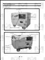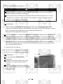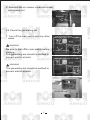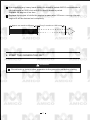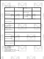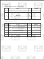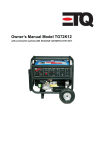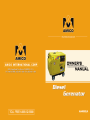
1
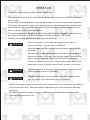
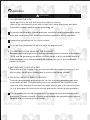
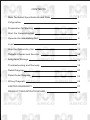
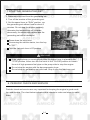
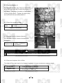
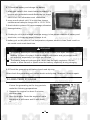
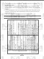
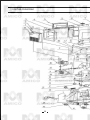
PREFACE
Thank you for purchasing AMICO diesel generators.
This operation manual will tell you how to operate and service your AMICO generation
set correctly.
Please read this manual before using the generating set to ensure the proper operation.
Follow the instructions to keep your generating set in the best working condition and
extend the life of it. If you have any commends or problem, please contact with our
sales company or the authorized agent.
This manual deals with the general items of the AMICO diesel generating set. However,
the manual may vary with the development of the products in the future.
Please give special attentions to warnings and cautions.
! WARNING
Failure to properly follow these precautions can result in
property damage, serious injury or DEATH!
Read all labels and the owner's manual before operating this
generator.
Operate only in well ventilated areas. Exhaust gas contains
poisonous carbon monoxide, and can be deadly. Always stop
engine before refueling. Wait 5 minutes before restarting.
Check for spilled fuel or leaks. Clean and/or repair before use.
Keep any sources of ignition away from fuel tank, at all times.
! WARNING
Indicates that the severe personal injury even death will result
if the instructions are not followed.
! CAUTION
Indicates that the serious personal injury or equipment damage will result if the instructions are not followed.
AMICO diesel generating set will meet your requirement if you operate it according to
the manual instruction. Otherwise serious personal injury and equipment damage
will result.
So, AMICO reconfirms that ou must to read and understand this manual before
operating the generating set.
OP
ST
WARNING:
! CAUTION
1. TO PREVENTTHE FIRE
Never add fuel to the fuel tank while the engine is running.
Wipe off the overflowed fuel oil with a clean cloth. Keep explosives and other
flammable products away from the generating set.
To prevent the fire and to I~rovide adequate ventilation, keep the generating set at
least one meter away from buildings and other equipment during operation.
Operate the generating set on a level surface,
Do not put the generating set indoors while the engine is hot.
2. TO PREVENT FROM INHALING THE EXHAUST
Exhaust gas contains poisonous carbon monoxide, which is harmful to the health.
Never use the generating set at the confined places or poor ventilated locations,
If it's necessary to run the generating set indoors, be sure to provide the adequate ventilation.
3. BE CARE NOT TO BE SCALDED
The muffler and the engine body are very hot while the engine is running or just
after running, do not touch these parts to prevent from being scalded.
4. ELECTRIC SHOCKS, SHORT CIRCUITS
To avoid electric shocks or short circuits, do not touch the generating set when
your hands are wet. This generating set is net waterproof, so it should not be
used in a place exposed to rain snow or water sprays. Use of the generating set
tor in a wet place can cause short circuits and electric shocks during operation.
The generating set should be grounded to prevent electrical shocks from faulty
appliances. Connect a length of heavy wires between the generating set s ground
terminal and an external ground source.
Do not hook up tools or other apparatus to generating set rator before it has been
started. If equipment is attached, generator starting may cause sudden movements of the equipment and result in injuries and accidents. Be sure to disconnect any apparatus from the generating set or prior to starting.
! CAUTION
Most appliance motors require more than their rated wattage for start-up.
Do not exceed the specified current limit of any socket.
Do not connect the generating set to a household circuit. This could cause
damage to the generating set and to electrical appliances in the house.
CONTENTS
Main Technical Specifications and Data
1
Cofiguration
2
Preparation for Starting
3
Start the Generating Set
7
Operate the Generating Set
9
Load
10
Stop the Generating Set
14
Periodic Checks and Service
14
Long-term Storage
18
Troubleshooting and Remedy
19
Detail Diagram
20
Panel Detail Diagram
24
Wiring Diagram
26
LIMITED WARRANTY
27
PRODUCT REGISTRATIONCARD
28
1. MAIN TECHNICAL SPECIFICATIONS AND DATA
Model
AH4000LN
Item
Rated frequency (Hz)
60
Rated power (kVA)
4.0
Rated voltage (AC)(V)
120/240
Rated current (AC)(V)
33/16.5
3600
Rated revolution speed(r/min)
Generator
Power factor (cos )
1
Controlled silicon self excitation
constant voltage
Excitation mode
DC output
12V/8.3A
Operation mode
12 hour continuous running
Coupling method
Transmission rigid connection
Engine Model
AHD186
165
Gross weght(kg)
950x565x760
Overall dimensions(LxWxH)(mm)
1
2.CONFIGURATION
2.1 Parts name
AC output
DC output
Engine starter switch
Fuelfiller cap
Lifting eye
Low oil pressureg lamp
Exhaust
Outlet fo
cooling air
2
2.2 Control panel
AH6000LN
3. PREPARATION FOR STARTING
3.1 Selection and handling of the fuel oil
Selection of fuel oil
Only use the light diesel, which is most suitable for the engine,
Keep dust and water out of the fuel
When filling the fuel tank from drums, make sure that no dust or water is mixed in
the fuel. Otherwise the serious fuel injection pump and nozzle problems will result
Do not overdill
Overfilling is very dangerous, De not fill the tank beyond the top of the red plug
inside the fuel oil fillter.
! WARNING
Refuel in a well-ventilated area with the engine stopped.
Do not smoke or allow flames or sparks in the area where the engine is refueled or where the fuel oil stored,
Do not overfill the tank, make sure the filler cap is securely closed after
refueling.
Be careful net to spill fuel when refueling. If any fuel is spilled, make sure the
area is dry before starting the engine.
3
3.2 Check and refill the engine oil
! WARNING
Always check the engine oil level with the generating set on a level surface
before starting and refill if necessary.
The engine may be damaged if operated with insufficient engine oil, it is also
dangerous to refill too much engine oiI as sudden increase in engine speed
may be caused by its combustion.
! WARNING
AMICO series generating set are equipped with Iow oil warning system This
system will stops the engine automatically when the oil level falls below the lower
level. This prevents accidents such as bearing seizures, etc.
Select the most applicable engine oil
It is very important to select the applicable engine oil for keep up the performance
and life of the generating set, If inferior engine oil is used, or it your engine oil is
not replaced periodically, the risk of piston seizure, piston ring sticking and accelerated wear of the cylinder liner, bearing and other moving components increases
significantly. So the generating set life will be shortened AMICO recommends
CC/CD oil classified by APl. Choose the applicable viscosity oil according to the
local ambient temperature.
3.3 Service the air cleaner
1. Screw off the wing nut remove the air
cleaner cover and take out the element.
! WARNING
Do not wash the element with
detergent.
Replace the element when its output
decrease or a bad exhaust color is
noticed.
Never run the generating set without
the element, otherwise the rapid engine
wear will result.
Air cleaner inspection port cover
4
2. Reattach the air cleaner cover and screw
on the wing nut.
Elelment
3.4 Check the generating set
1. Turn off the main switch and any other
loads.
Low oil warning lamp
! WARNING
Be sure to turn offthe main switch before
starting.
The generating set should be earthed to
prevent electric shocks.
AC output receptacle
! WARNING
The generating set should be earthed to
prevent electdc shocks.
Ground terminal
Ground terminal
5
2. Handling of dual voltage type generating sets
Be sure to place the changeover switch
in the correct position for the rated voltage of the working instrument.
Change-over switch
! CAUTION
The main switch should always be kept in the "ON" position during operation.
Before starting the engine, be sure to turn the switches of the working instrument (lighting apparatus, motor, etc.) to their "OFF" position. If the switches
are not "OFF", the sudden application of load when the engine is started
could be very dangerous.
3-5 How to open the cabinet door and covers of AMICO LN series
generating set
1. Open the cabinet door for daily inspection.
Tum the lever counter clockwise and raise
the door.
2. Loosen the bolt of the air cleaner check
port cover to check the air cleaner.
3. Screw off the wing nut to open the cover,
then check the nozzle cover.
3.6 Break-in period operation
The first 20hrs are the break-in period of the engine, the operator must obey to
following items:
Warm up the engine 5 minutes after the initial starting. Run the engine at Iow
speed and zero load before the engine becomes warm
6
Avoid applying any heavy loads during the break-in pedod AMICO recommends to
run the engine at 3600 r/min with 50% load in break-in period.
Replace the engine oil on time.
Replace the engine oil while the engine is warm after 20-hours -running. the old
engine oil will be drained out completely.
Approx. one month or 20hours
Every 3 months or 100 hours
4. START THE GENERATING SET
! WARNING
Do not hook up tools or other apparatus to the generating set before starting.
7
1. Starting
Open the fuel cock.
Set the engine speed lever at "RUN"
position.
Engine speed lever
Engine speed aver
Photo shows
shows RUN
RUN position
position
Photo
Turn the starting key clockwise to
"START" position.
Remove your hand from the key as soon
as the engine starts.
If the starting motor does not start after
10 seconds, wait 15 seconds before starting it again.
Engine starter key
! CAUTION
Run the starting motor for long time will cost the battery power greatly even
burn out the molor.
Always leave the starting key at "ON" position while the engine is running.
8
2. Battery
1.when you install it,frist check batteryís polarity if it
is same with generatorís anode &cathode line,check
volt if it is 12.3V,otherwise must electricize,
2.every month check volt if it is right,free charge
maintenance batteryís charge,volt is 13.5V-14.5v
3.check electric systerm if it have creepage,otherwise
damage battery,
4.if batteryís volt is not enough,electrica energy is low,please remove of battery and
electricize, on time,only have 5-6hours is ok,
5.battery put on the place of low temperature,dryness,aeration,clean,three month or
six month must need electricize,
5. OPERATE THE GENERATING SET
5.1 Operate the generating set
1. Warm up the engine without load three
minutes.
Fuel injection limiting bolt
2. Concerning the generating set with Low
Oil Warning System, check that the Oil
Alarm Lamp is net lit.
9
! CAUTION
For the generating set with Low Oil Warning System, the Oil Alarm Lamp will
activated by Iow oil pressure or engine oil shortage, simultaneously, the engine will stop. The engine will stop immediately if restarted without refilling
the engine oil Check the oil level and refill.
Do not loosen or readjust either the engine speed limiting bolt or fuel injection
limiting bolt, otherwise, the performance will be affected.
5.2 Checks during the running
1. Whether there is abnormal sound or vibration;
2. Whether the engine misfires or runs rough;
3. Check the color of the exhaust. (Is it black or too white?)
If you notice any of the above-mentioned phenomenon happened, stop the ehgine and find out the fault cause or contact with AMICO agent.
! CAUTION
If the engine has been running, the muffler will be very hot, Be careful not to
touch the muffler.
Never refill the fuel tank while the engine is running.
6.LOAD
! CAUTION
DO not start 2 or more machines simultaneously Start them one by one.
Do not use floodlights together with other machines.
10
6.1 AC application
1. Be sure to run the generating set at rated speed, otherwise capacitor will produce
the forced excitation. If the running is for a long time under such condition.
capacitor will be burned out,
2. After switching on the air switch, observe the voltmeter on the panel of the control
cabinet, the voltmeter should point to 120V + 5%(60Hz) for single-phase gener
ating set; 120V/240V+ 5%(60Hz) for single-phase generating set, then the loading
can be carried out.
3. When the double voltage generating set changes over the voltage, the air sw.~,l
should be set at "OFF" position Otherwise the generating set and electric devices
will be burned out and damaged.
4. Connect the equipment to the generating set in order Forthematterofthemotor
load, firsPy the heavy-duty motor should be connected, then the light-duty motors
If the operation is false, the generating set will lag or stop suddenly It is necessary to unload the generating set immediately and turn offthe main switch and do
checks.
! NOTE
If overloading of the circuit trips the AC circuit protector, reduce the electrical
load on the circuit, and wait a few minutes before resuming operation.
6.2 DC application
1. DC terminals are only for charging 12V battery,
2 Set the air switch at "OFF" position while charging. On the 12V output terminals,
a charge switch can be connected so the switch can be used for on-and-off
purpose
3. Loncerning the automatic type battery with the leads, be sure to disconnect the
negative leads of the battery while charging.
11
! CAUTION
Connect the positive and negative poles of the battery with the positive and
negative poles of DC terminals separately. Do not confuse them, otherwise
the battery and generating set will burn out
Do not connect the positive pole of the battery with its negative pole, otherwise the battery damage will result,
Do not connect the positive pole of the DC terminal with its negative pole.
otherwise the generating set damage will result,
When a large capacity battery is charged, excessive current flows, the fuse
for the direct current will burn out,
Do not run the generating set while it is still connected with the battery,
Do not use DC12V and AC at the same time.
! CAUTION
Battery exhausts explosive gas. Keep sparks, flames, and cigarettes away
form the battery. To prevent from creating a spark near the battery, always
connect the charging cables to the battery first and only then to the generating set. When disconnecting, you should disconnect the cables at the generating set first.
Charge the battery at a well-ventilated place,
Before charging, remove the cap from each cell of the battery.
Stop charging if the electrolyte temperature exceed 45 C.
12
6.3 Electrical appliance particularly motor-driven equipment will produce very
high current while starting, the below table provides the reference for connecting
these apparatus to the generator set.
WATTAGE
TYPE
STARTING RATED
Incandescent
lamp
Heating
appliance
Xl
Xl
Fluorescent
lamp
X2
Xl .5
Motordriven
equipment
TYPICAL
APPLIANCE
Incandescent
lamp
TV
X2
APPLIANCE
Incandescent
lamp
100W
40W
Fluorescent
lamp
X3~5
EXAMPLE
Refrigerator
150W
13
I00VA
(W)
I00VA
(W)
80VA
(W)
60VA
(W)
450-750VA
(W)
300VA
Fluorescent
lamp
Refrigerator
Electric
fan
STARTING RATED
7.STOP THE GENERATING SET
1. Disconnect the load from the generating set.
2. Turn off the breaker of the generating set.
3. Set the speed lever at "RUN" position, run
the generating set without load for about 3
minutes. Do not stop the engine suddenly,
otherwise the temperature will increase
abnormally, the nozzle will blocked and the
generating set will be damaged
Press down the stop lever
Concerning the electric starter, turn the key
to "OFF ",
Turn the fuel cock lever to"S"position
stop lever
With engine speed lever
at STOP position
! WARNING
If the engine keep on running even after the speed lever is placed at the
"STOP'position, either turn the fuel cock to the "CLOSE"position or loosen
the nut of high pressure fuel pipe on the pump side to stop the engine.
Do not stop the engine with the decompression lever.
Do not stop the generating set with load. Stop it after the load removed.
8. PERIODIC CHECK AND SERVICE
Periodic check and service are very important for keeping the engine in good condition and durable. The chart below indicates what checks to make and when to make
them.
14
! WARNING
Shut off the engine before performing any service. If the engine must be run,
make sure the area is well ventilated. The exhaust contains poisonous carbon monoxide gas.
After the generating set has been used, clean it immediately with a cloth to
prevent corrosion and to remove sedimenh.
Interals
Item
Check and refill fuel oil
Drain out fuel oil
Every
day
First month
or 20 Hrs
Third month sixth month Every year or
or 100 Hrs or 500 Hfs
1000 Hrs
Check and refill engine oil
Check for oil leakage
Check and tighten fastening parts
Replace engine oil
Tighten the
Cylinder head
bolts
(First time)
(Secondtime)
(Replace if
necessary
Clean engine oil filter
Replace air cleaner
element
(Service more frequently when
used in dusty areas)
(Replace)
Clean fuel oil filter
(Replace)
Check fuel injection pump
Check nozzle
(Replace if
necessary)
Check fuel pipe
Adjust clearance of intake/
exhaust valves
Fisrt time)
Grind intake/exhaust valves
Replace piston ring
Every month
Check battery electrolyte
Check carbon brush and slip ring
Check insulation resistance The generating set has been stored more than lOdays
Note:"
" indicates that special tools are required, please contact with AMICO agent.
15
8.1 Replace engine oil
Remove the oil filler cap. Remove the drain
plug and drain the old oil while the engine is
still warm. The plug is located on the bottom
of the cylinder block. Tighten the drain plug
and refill with the recommended oil.
Oil fillercap/Dipstick
Drain plug
8.2 Clean the engine oil filter
Cleaning
time
Every 6 months or 500
hours
Replace if necessary
Oil filter
Drain plug
8.3 Replace the air cleaner element
Do not clean the air cleaner element with
detergent.
Replace time
Elelment
Every 6 months or
500 hours
! CAUTION
Never run the engine without the element or with a defective element.
8.4 Clean and replace fuel oil filter
The fuel oil filter also has to be cleaned regularly to insure maximum engine output.
Clean time
Every 6 months or 500 hfs
Replace time
Every year or 1000 hrs
16
1. Drain out the fuel from the fuel tank.
Loosen the three
small screws and
remvoe the fuel filter
2. Drain out the fuel from the fuel tank.Screw off the small screw of the fuel cock
and pull out the filter from the filler port.
3. Wash the filter thoroughly with diesel fuel.Loosen the fastening nut, bottom cover
and delivery discs for cleaning the deposit carbon.
8.5 Tighten cylinder head bolt
Tightening the cylinder head bolt requires a special tool. Do not try yourself. Contact
with AMICO agent.
8.6 Check the injection nozzle and fuel injection pump
1. Adjust the clearance of the intake/exhaust valves,
2. Grind the intake/exhaust valves.
3 Replace the piston ring.
All these operation require special tools and skills, contact with your AMICO agent.
! WARNING
Do not perform the injection nozzle test near an open fire or any other kind of
fire. The fuel spray may ignite. De not expose bare skin to the fuel spray The
fuel may penetrate the skin and cause injury to the body. Always keep your
body away from the nozzle.
17
8.7 Check the battery and charge the battery
1.when you install it,frist check batteryís polarity if it
is same with generatorís anode &cathode line,check
volt if it is 12.3V,otherwise must electricize,
2.every month check volt if it is right,free charge
maintenance batteryís charge,volt is 13.5V-14.5v
3.check electric systerm if it have creepage,otherwise
damage battery,
4.if batteryís volt is not enough,electrica energy is low,please remove of battery and
electricize, on time,only have 5-6hours is ok,
5.battery put on the place of low temperature,dryness,aeration,clean,three month or
six month must need electricize,
! WARNING
The battery electrolyte contains sulfuric acid. Protect your eyes, skin and
clothing. In case of contact, flush thoroughly with water and get prompt medical attention, especially if yur eyes are affected.
The battery exhaust hydrogen gas, which can be highly explosive. Do not
smoke or allow flames or sparks near the battery, especially during charging.
8.8 Check the generating set carbon brush and slip ring
Often check the generating set carbon brush and slip dng. Readjust if there is spark.
9. LONG-TERM STORAGE
If store the generating set for long periods,
make the following preparations.
1. Operate the engine for about 3 minutes
and then stop.
2. Stop the engine. Drain the engine oil while
the engine is still warm and fill with fresh
oil.
18
Oil fillercap/distick
Drain plug
The diesel engine can not start
19
The specified oil level should be between
the upper level and lower level.
Clean the nozzle
Start the engine according to the start procedures included in this book.
Charge it or replace it with a new one.
Turn the main switch to ON position.
Replace the carbon brush.
Check the engine oil level.
The nozzle has dirty.
The speed and force to pull the recoil starter are not enough,
The battery has no electricity.
Main switch not be turned on,
The carbon brush already worn.
Adjust it according to the requirements.
Replace the AVR
The rated speed can not attached.
AVR is damaged.
The contact of the socket is not good. Adjust the socket.
Set the leverto START position
The governor lever is not at START
position.
Turn it to START position
Fuel cock is not at START position
Remove the nozzle and repair it at test
table.
Refill the fuel oil
Fuel oil is not sufficient
Fuel injection pump and nozzle do
not delivery the fuel or delivery insufficient fuel.
Remedy
Fault Cause
3. Remove the screw plug on the cylinder head cover and refill 2cc engine oil, then
put the plug in place,
4. Turn the engine 2~3 seconds with the decompression lever set at the non-compression position, and the starting key at the "START" position.( (Do not start the
engine.)
5. Pull the decompression lever up. Pull the recoil starter slowly. Stop when you feel
resistance.( at this position, both intake/exhaust valves are closed to prevent the
engine from the rust.)
6. Wipe off the oil and dirt from the engine and store in a dry place
10.TROUBLESHOOTING AND REMEDY
The generating set can
not generate
11.DETAIL DIAGRAM
20
21
Number
1
2
3
4
5
6
7
8
9
10
11
12
13
14
15
16
17
18
19
20
21
22
23
24
25
26
27
28
29
30
31
32
33
34
35
36
37
38
39
40
41
42
43
44
45
Quantity
Part Description
Silencer Cover
Silencer Bend
Left Board
Back Door
Fixing Sleeve For Observing Bore
Fixing Sleeve For Input Of Fule Tank
Main Cover
Swich
Air Filter Baffle
Accelerator Electomagnet
Right Board
Output Panel Assembly
Cover Of Observing Bore For Air Filter
Cover Of Fuel Tank
Buoy For Oil Leverl Indication
Fuel Tank
Lining
Shock Absorption Mat
Clip
Clip
Fuel Inlet Pipe
Fuel Filter Assembly
Fuel Inlet Pipe
Fuel Leak-off Pipe
Cover Of U Type Chamfer
U Type Chamfer
Support Of U Type Chamfer
Output pipe
Gasket Of Silencer
Upper Silencer
Low Silencer
Back Cover Of Alternator
Bracket
Shock Absorption Mat
Tow Structure Of Accelerator
Electomagnet
Bracket Of Electomagnet
Long Cover
Chassis
Rolling Wheel On Chassis
Flat Key
Pin
Motherboard Of Accumulator
Accumulator
Bolt
22
1
1
1
1
1
1
1
1
1
1
1
1
1
1
1
1
1
1
1
1
1
1
1
1
1
1
1
1
1
1
1
1
1
4
1
1
1
1
1
4
4
4
1
1
1
Part Number
AH4000LN001
AH4000LN002
AH4000LN003
AH4000LN004
AH4000LN005
AH4000LN006
AH4000LN007
AH4000LN008
AH4000LN009
AH4000LN010
AH4000LN011
AH4000LN012
AH4000LN013
AH4000LN014
AH4000LN015
AH4000LN016
AH4000LN017
AH4000LN018
AH4000LN019
AH4000LN020
AH4000LN021
AH4000LN022
AH4000LN023
AH4000LN024
AH4000LN025
AH4000LN026
AH4000LN027
AH4000LN028
AH4000LN029
AH4000LN030
AH4000LN031
AH4000LN032
AH4000LN033
AH4000LN034
AH4000LN035
AH4000LN036
AH4000LN037
AH4000LN038
AH4000LN039
AH4000LN040
AH4000LN041
AH4000LN042
AH4000LN043
AH4000LN044
AH4000LN045
Number
46
47
48
49
50
51
52
53
54
55
56
57
58
A
B
C
D
E
F
G
H
I
J
K
L
M
N
Quantity
Part Description
Pressingplate Of Accumulator
Pulling Wire For Throttle
Pulling Wire For Turn-off
Alternator
Output Wind Leading Shaft
Manostat
Gasket Of Output Bore
Cf Series Disel Engine
Pulling Role For Accelerator
Intake Wind Leading Shaft
Pressing Plate Of High Pressure Fuel Pipe
Shock Preventing Mat
Shock Preventing Holder
M6*16 Bolt,Flat Key
M6*8 Bolt
M4*8 Bolt
M6*12 Bolt
M10*45 Bolt
M6*16 Bolt
M8*25 Bolt
M6*12 Bolt
M5*8 Bolt
M6 Nut
M8 Nut*Flat Spring Washer
M10 Nut*Flat Spring Washer
M5*12 Bolt
M6*22 Bolt
23
1
1
1
1
1
1
1
1
1
1
1
1
1
41
4
4
4
4
4
5
17
12
2
6
12
2
2
Part Number
AH4000LN046
AH4000LN047
AH4000LN048
AH4000LN049
AH4000LN050
AH4000LN051
AH4000LN052
AH4000LN053
AH4000LN054
AH4000LN055
AH4000LN056
AH4000LN057
AH4000LN058
AH4000LN059
AH4000LN060
AH4000LN061
AH4000LN062
AH4000LN063
AH4000LN064
AH4000LN065
AH4000LN066
AH4000LN067
AH4000LN068
AH4000LN069
AH4000LN070
AH4000LN071
AH4000LN072
12.PANEL DETAIL DIAGRAM
24
Number
Part Description
Quantity
1
2
3
4
5
6
7
8
9
10
11
12
13
14
15
16
17
18
19
20
21
Panel
M6X12 Bolt
Starter Switch
M4X30 Bolt
3 Prong Socket
M4X15 Bolt
M5X25 Bolt
Positive DC Port
Negative DC Port
Grounded Bolt
Integrating
DC Fuse
Breaker
Breaker Bracket
4 Prong Socket
Current Adjusting Switch
Oil Alert Lamp
Voltmeter
Wiring Harness
Box
Hour meter
1
6
1
4
2
2
2
1
1
1
1
1
1
1
1
1
1
1
1
1
1
25
Part Number
AH4000LN073
AH4000LN074
AH4000LN075
AH4000LN076
AH4000LN077
AH4000LN078
AH4000LN079
AH4000LN080
AH4000LN081
AH4000LN082
AH4000LN083
AH4000LN084
AH4000LN085
AH4000LN086
AH4000LN087
AH4000LN088
AH4000LN089
AH4000LN090
AH4000LN091
AH4000LN092
AH4000LN093
13.WIRING DIAGRAM
26
Limited Warranty
AMICO provides a one-year limited warranty for AMICO generators. All products covered by this
limited warranty which are used in commercial applications are warranted to be free of defects in
material and workmanship for 90 days from the date of original purchase. AMICO warrants to the
original purchaser that the alternator and engine for its portable generator will be free from the
defects in materials or workmanship for the items and period set forth below from the date of original
purchase.
During warranty period, AMICO will repair or replace any part that, upon examination by AMICO,
is found to be defective under normal use and service. Starting batteries are not warranted by
AMICO. All transportation cost under warranty including return to the factory if necessary, are to
be prepaid by the purchaser. All decisions of AMICO with regard to this limited warranty shall be
final.
This warranty does not cover:
1.Merchandise sold as reconditioned, used as rental equipment, or floor or display models.
2.Merchandise that has become damaged or inoperative because of ordinary wear, misuse, cold,
heat, rain, excessive humidity, freeze damage, use of improper chemicals, negligence, accident,
over loading, over speeding, improper maintenance, the use of accessories or attachments not
recommended by AMICO, or unauthorized repair or alterations.
3.Expendable parts or accessories supplied with the product which are expected to become
inoperative or unusable after a reasonable period of use.
4.Any incidental, indirect or consequential loss, damage, or expense thatmay result from any
defects, failure or malfunction of the products is not covered by this warranty.
For service, please e-mail to or fax to 562-908-1899, Warranty service can be performed only by
AMICO authorized service facility. This warranty will not apply to service at any other facility. At
the time of requesting warranty service, evidence of original purchase date must be presented.
27
PRODUCT REGISTRATION CARD
For more efficient customer service, please fill out the information below and mail to our
produce Warranty and Registration Division:
Amico International Corp.
4825 Gregg Road,
Pico Rivera, CA 90660, U.S.A
Tel: 562-908-0088 Fax: 562-908-1899
Website: www.amicousa.com
Model No.
Purchase Date.
Engine Serial No.
[ ] Retail location
Purchased from:
Name
Address
Telephone w/area code
[ ] Private Consumer
/
/
[ ] Other
Purchase Price
Purchased: [ ] NEW or [ ] USED
Consumer information :
Name
Address
City
State
Country
Are you a:
[ ] Business
Product Usage Information :
How often will you use this product?
[ ] Everyday
[ ] Emergency use only
Telephone w/area code
Suite or Apt No.
Zip Code
or
[ ] Residence
[ ] Periodically
[ ]Other
What type of application will you use this produce in ?
[ ]Heavy Commercial
[ ]Moderate Commercial
[ ]Light Commercial
[ ] Tradeshows
[ ] Heavy residential
[ ] Moderate Residential
[ ]Light Residential
[ ]Camping, backpacking
[ ]Other
IMPORTANT I NFORIJAT I ON
It is critical to your warranty that the original point of sales receipt be retained by current
consumer, and in order to comply with our product Warranty Statement you must return this
registration card within 15 days of original purchase. Product warranty is valid from original
date of purchase.
28
List for comments from users
Date of Manufacture
Model Number
Name of user
Occupation
Address of user
Place of purchase
Packaging conditions
Operating conditions
Parts Conditions
Malfunction problem
Opinions or suggestions
Note: Please mail the above card to:
Amico International Corp.
4825 Gregg Road,
Pico Rivera, CA 90660, U.S.A
Tel: 562-908-0088 Fax: 562-908-1899
Website: www.amicousa.com
Appendix:
1. Attached list of tools, fittings, and subassemblies
Order No.
Name
Qty
1
4-Stroke Air-cooled Diesel Generator Set
1
2
Kit
1
3
Plastic cover
1
4
Plug and power supply
1
Remarks
2. Attached technical documents
Order No.
Name
Qty
1
Air cooled diesel generator manual
1
2
Diesel engine instruction manual
1
3
Diesel engine parts listing
1
4
Certificate of Quality
1
5
Packing List
1
Remarks