1
FLAMINGOS at the KPNO 4-m
An Observer's Guide
Nick Raines & Richard Elston
Version 2.34, 2006 April 04
(4m figure © A. R. King/NOAO/AURA/NSF)
FLAMINGOS@4-m, Ver. 2.34, 2006 Apr 04
Page 1 of 44
Contents
I. FLAMINGOS + KPNO 4-m Overview
II. Starting FLAMINGOS
III.Nightly Startup Tasks
A. FLAMINGOS Setup
B. Startup on the Sky
IV.Imaging with FLAMINGOS
A. Overview
B. Wheel Setup for Imaging
C. Configuring an Exposure
D. Taking an Image at a Single Pointing
E. Taking Dithered Images
F. Offsetting the Telescope from Flamingos1a or 1b
G. Taking Darks
V. Taking Spectra with FLAMINGOS
A. Overview
B. Long Slit Alignment
C. MOS Plate Alignment
D. Taking Spectra Once the Slit or MOS plate is Aligned
E. Taking Flats & Wavelength Calibrations
VI.Shutting Down at the End of the Night
VII.At the End of Your Run
VIII.Troubleshooting
IX.Contacts & Further Information
X. Acknowledgements & Other Bits
Appendices
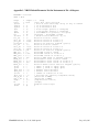
Appendix 1. FLAMINGOS Command Listing and Partial Description of Function
A. Basic Instrument Configuration Commands
B. Basic Imaging Configuration and Acquisition Commands
C. Basic Spectroscopy (MOS and Long Slit) Configuration and Acquisition Commands
D. Advanced Imaging and Spectroscopy Commands
E. Telescope Information and Motion Controller
F. Resetting the MCE4 Array Controller, the Motor Controller, and the Perlepow
G. Data Transfer and Data Compressing, Data Taping & DVD Burning
H. Instrument Engineering Commands
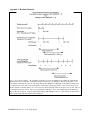
Appendix 2. Readout Schematic
Appendix 3. XBOX Default Parameter List for Instrument at PA = 90 degrees
Appendix 4. Additional Notes on MOS Plates
FLAMINGOS@4-m, Ver. 2.34, 2006 Apr 04
Page 2 of 44
I. FLAMINGOS + KPNO 4-m Overview
FLAMINGOS is the FLoridA Multi-object Imaging Near-ir Grism Observational Spectrometer. This manual
provides the user with a good portion of the tools needed to successfully take data with FLAMINGOS at the
KPNO 4-m telescope. A knowledge of basic unix commands is assumed.
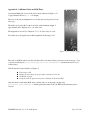
FLAMINGOS is comprised of two cryogenic dewars. The MOS dewar, closest to the telescope backplane,
contains a wheel which can position 11 slit plates in the Cassegrain focal plane. The Camera dewar,
immediately following the MOS dewar contains all of the powered optics, filters, stops, grisms, and the detector
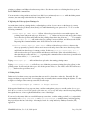
array. A functional diagram showing the relative layout and connections to the various electronics is shown in
Figure 1.
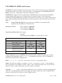
Array:
Hawaii II 2048x2048 HgCdTe science grade array, divided into four quadrants with 8
amplifiers each (32 amplifiers for the whole array).
Linearity at 1.0V bias:
0.5% non-linear at 25,000 ADU
2% non-linear at 35,000 ADU
>3% non-linear at 40,000 ADU
Plate Scale and Field of View: 0.316"/pixel
10.8' FOV
Typical image quality (FWHM) = 2–3 pixels = 0.63" – 0.95".
Detector Characteristics:
Imaging
Spectroscopy
1.0
0.75
~50,000
~38,000
Target Count level (ADU)
25,000 – 35,000
15,000 – 20,000
CDS Read Noise without
Differential Amplifier (e)
~40
~40
Gain (e / ADU)
~4.9
~4.1
Bias Voltage (Volts)
Full Well (ADU)
N.B. The default bias on boot of the MCE4 array controller is 0.776 V, which is not used in any observing
configuration; the initialization script initflam.pl automatically sets the bias to 1.0 V for imaging, but
queries the user if they wish to change the bias.
Filters: J, H, K, Ks, JH (0.9 µm – 1.8 µm), and HK (1.25 µm – 2.5 µm) bandpass filters.
Grisms: Two grisms are available, covering the JH (0.9 µm – 1.8 µm) and HK (1.25 µm – 2.5 µm) bandpasses.
The HK grism may be used with the HK filter to obtain H- and K-band spectra in first order, or it may be used
with the JH filter to obtain H-band in first order, and J-band in second order.
Long Slits: 2, 3, 6, 9, 12, and 20-pixel slits are available; the 3 and 6 pixel slits cover much of the chip but the
others slits cover approximately two-thirds of the chip. All of these long slits are located on the MOS wheel.
An extra 3-pixel long slit is located in one of the 11 MOS positions.
FLAMINGOS@4-m, Ver. 2.34, 2006 Apr 04
Page 3 of 44
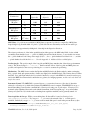
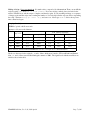
Spectral Characteristics
Filter / Grism
Combination
JH-bandpass +
JH-grism
HK-bandpass +
HK-grism
JH-bandpass +
HK-grism
Band
R = λ / δλ
Dispersion
R = λ / δλ
(2 pix slit)
(Å/pixel)
(3 pix slit)
J
1400
4.68
960
H
1800
4.68
1250
970
8.55
650
K
1300
8.55
865
J (2nd order)
1500
4.4
1000
H
MOS Plates: 11 positions are available for MOS plates; at present 1 position is occupied by a MOS plate
shaped single long slit with width of 3 pixels; 3 pixel wide slits are customarily used at the 4-m telescope.
The masks cover approximately ±290 pixels of the chip in the dispersion direction.
The science grade array is offset in the spatial direction with respect to the MOS wheel field of view, which
essentially means that the lower ~70 pixels of a MOS plate will not hit the detector. Lower in this case means
the 70 pixels furthest North if the position angle (PA) is 0º, the 70 pixels furthest East if the PA is 90º, and the
70 pixels furthest South if the PA is 180º. See also Appendix 4: Additional Notes on MOS plates.
Position Angles: The position angle of the long slits and MOS plates matches that of the telescope instrument
rotator. The allowed range is -0.6º to +180º. Small rotational offsets of the long slits and MOS plates are
possible, and required, as the rotator positioning is too coarse for accurate slit positioning.
Mechanisms: The MOS dewar contains the Decker and MOS wheels; the Decker wheel contains an imaging
hole, a psuedo dark, and aperture masks to baffle stray light before the MOS wheel. The Camera dewar contains
the Filter, Lyot, and Grism wheels; the Lyot wheel contains Lyot stops for the KPNO 2.1-m and 4-m telescopes,
and for the MMT; the Grism wheel contains the two grisms, two imaging apertures, and the only truly dark cold
stop in the system.
Instrument Control: FLAMINGOS is operated via an ssh connection from tan to flmn-4m-1a (hereafter
referred to as flamingos1a), which is the primary FLAMINGOS control computer. FLAMINGOS is set up so
that all data taking is run from the command line of flamingos1a using a set of perl scripts1. Flamingos1a is
mounted on the right-hand electronics rack with the instrument, in the Cassegrain cage. A second machine,
flamingos1b (flmn-4m-1b) is in the rack as a backup data acquisition machine, and is generally turned off.
Data Acquisition & Storage: While you are taking data, all data will be located on flamingos1a in
/data/4mguest/<UTDATE>/. If you type df -h, you can see how much of the 68 GB disk space is
available; similarly if you type du -h, you can see how much disk space is used in the present directory (the
1 Located in /usr/local/flamingos/, in the directories perl_all_tel/, perl_kp4m/,
flamingos.headers.lut/, and flamingos_modules/.
FLAMINGOS@4-m, Ver. 2.34, 2006 Apr 04
Page 4 of 44
-h option is for human readable format, and it prints values out with KB, MB, and GB suffixes as appropriate).
Data Analysis: An IRAF session will be running on flamingos1a. Simple analysis tasks such as quick image
arithmatic, image stacking, and image statistics can be performed with it while taking data. There are no
pipeline reduction packages installed on flamingos1a for imaging or spectroscopy data. If you wish to reduce
data simultaneously while taking data, we recommend that you transfer it to nutmeg, and do so there. However,
if the night is shot by clouds, several non-distribution IRAF packages have been installed on flamingos1a (e.g.
xdimsum) which may be useful . Let us know if you find any problems.
Data Display: FLAMINGOS images are automatically displayed in ds9, into frame buffers 1 and 2, with odd
images in buffer 1 and even images in buffer 2. Other noteworthy points:
ds9 toggles the frame before loading the newest image, so you sometimes can briefly see the previous
image in that buffer. You can choose to tile any of the buffers.
The image name appears in the file name box in ds9; data values and pixel coordinates are also shown.
ds9 can read the rudimentary World Coordinate Information (WCS) in the FLAMINGOS header, and it
displays the WCS compass arrows.
ds9 also has some very useful tools such as rulers. You should spend some time familiarizing yourself
with ds9 if you are mostly used to ximtool.
No other display program is available for automatically displaying the images as they are taken.
IRAF can load images into ds9 with the display command, however, loading images directly into ds9
(with the File Open buttons) is recommended, as it preserves the ds9 ability to scale the images (using
IRAF display suspends this ability).
Data Transport: Observers are responsible for removing their data from flamingos1a and transporting it to their
home institution. All data will be removed from flamingos1a immediately after your observing run. The
filesystem on flamingos1a is cross-mounted to the KPNO 4-m computer nutmeg, to which we recommend that
you first move the data. This is easily done by running the script Start.autocopy.4m.nutmeg.sh
(described in more detail in §III. Nightly Startup Tasks) on flamingos1a. Once the data are on nutmeg, you can
write it to nutmeg's DDS4 tape drive or DVD writer. Alternatively, you can ftp/scp the data to your home
institution or to your laptop; such data transport to your home institution may be quite slow, however (recently
the transfer rate from azure, at the 2.1-m, to Florida was only ~220 KB/s). For taping, we recommend that you
first compress, gzip, or bzip the data before writing it to tape with tar.
Image Size: Each FLAMINGOS frame is 16 MB in size! During a single night of imaging, it is possible to
take 8 – 16 GB of data (500 to 1,000 images). Pay attention to disk usage, and bring many tapes and/or DVDs
for data archiving.
Unix Tips: Many of the command names are quite long. However, if you type a portion of the command and
then hit the TAB key, you will be offered a list of possible completions to the command name. Similarly, the up
arrow key will allow you to go up through the history stack of commands entered on the command line. A
familiarity with basic unix commands (e.g ~, ls, cd, mkdir, rm, rmdir, cp, mv, history, df, du, ps, ctrl-c, ctrl-z,
jobs, kill, grep, wc, tar, mt, ssh, scp, ftp and the up and down arrow keys) is advised.
FLAMINGOS@4-m, Ver. 2.34, 2006 Apr 04
Page 5 of 44
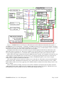
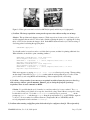
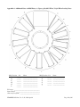
Figure 1. FLAMINGOS Functional Diagram. The relative layout and connnections between the various parts of
FLAMINGOS are shown shematically. A schematic of the MOS and Camera dewars is shown in the middle of the figure,
including the relative layout of the 5 internal mechanisms above the detector array, and the elements of the two electronics
racks are shown on either side of the dewars, much as they are in actuality.
The input beam from the telescope is shown in red; it passes first through the Decker wheel (a baffle wheel) to the
MOS wheel at the Cassegrain focus. The beam is collimated (some optical elements are not diagramed in this figure)
before passing through the Filter, Lyot, and Grism wheels, and then through the camera optics to the detector array.
Biases and Clock voltages are input into the array by MCE4, the array controller. All 4 quadrants of the array are read
out through all 32 output amplifiers; they are muxed down to 16 outputs at the preamp before they are sent into the 16
A/Ds on MCE4. The final output image is then sent via a fiber to the EDT frame grabber on the control computer
flamingos1a or 1b, where it is written to the data drive.
The observer makes a remote connection to flamingos1a/1b via the RJ-45 to fiber media converter at the instrument's
public network switch. The Baytech networked AC power control module is accessible from flamingos1a/1b or a Kitt
Peak machine, and the observer may toggle the power to MCE4, the Perle (formerly the Iocomm) serial port annex or the
Motor controller.
Three software daemons running on flamingos1a/1b transfer commands via the private network switch to the Perle
(which replaced the Iocomm), which passes the commands to the serial port of the correct device. The three devices are
the MCE4 Array Controller, the Motor Controller, and the LS208 Temperature Monitor.
FLAMINGOS@4-m, Ver. 2.34, 2006 Apr 04
Page 6 of 44
Halting A Script: Never type Ctrl-C. It is much safer to suspend a job with Ctrl-Z. Then you can kill the
script by typing jobs, and kill -9 %<job number>. If you are moving a wheel, please just wait for the
wheel to finish motion, and the script to complete, and then try again. If you are taking an image or a sequence
of images, wait until the script starts counting the number of seconds elapsed in the exposure before suspending
the script. Then run ufstop.pl -clean -stop, and start over. Never type Ctrl-C before the exposure
time counter has begun.
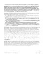
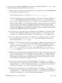
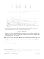
Imaging Sensitivity
FWHM = 3 pixels = 0.95 arcseconds
Aperture = 2.2 arcseconds diameter
Band
e/s for
mag = 15
10 σ limiting magnitude
sky
mag arcsec-2
e sec-1 pixel-1
60 seconds
600 seconds
3600 seconds
J
3450
15.7
180
18.8
20.0
21.0
H
4480
13.9
1250
18.0
19.2
20.2
K
4360
12.9
3050
17.5
18.7
19.7
Ks
3800
13.1
2210
17.6
18.8
19.75
These data are from the KPNO FLAMINGOS web site, www.kpno.noao.edu/manuals/flmn.
The above data were for the original J, H, and Ks filters, which were loaned to UF from NOAO and Gemini.
New J, H, and Ks filters were installed during the summer of 2003. The signal levels with the new filters are
similar to those in the table.
FLAMINGOS@4-m, Ver. 2.34, 2006 Apr 04
Page 7 of 44
II.Starting FLAMINGOS
When you arrive at the 4-m telescope, you may have to bring up the FLAMINGOS windows and initialize the
system (it should have been done during the checkout night). Steps 1–6 of this procedure will hopefully only
need to be done once at the beginning of your run; however, you may need to repeat this process during the
course of your observing time if you get logged out, or if the system crashes.
The observer interface is from the tan console. There are three monitors, labeled (from left to right) 0.1, 0.0,
and 0.2. The setup procedure described below will utilize the center monitor for overall login and image
display, the lefthand monitor for FLAMINGOS control, and the righthand monitor for IRAF tasks.
The full startup procedure follows:
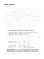
1. Log on to tan. The login is 4meter; the password ______________(taped to the edge of the monitor).
2. Once the desktop has come up:
Quit out of any automatically started windows.
On the middle monitor (tan:0.0), open either a terminal from the toolbar at the bottom of the screen or a
new xgterm by right clicking the mouse within the desktop, and selecting xgterm from the menu.
Type xhost +flmn-4m-1a to allow remote display to tan from flmn-4m-1a.
3. Using the xgterm, ssh into the FLAMINGOS control computer, hereafter known as flamingos1a, as
4mguest:
4meter@tan%
ssh -X -l 4mguest flmn-4m-1a
password = ________
(See the FLAMINGOS binder of manuals for the password).
4. Start ds9 on tan's center monitor
4mguest@flmn-4m-1a{1}
ds9 &
5. Set the display to tan's right monitor (tan:0.2), open an xgterm, and start IRAF:
4mguest@flmn-4m-1a{2}
4mguest@flmn-4m-1a{3}
setenv DISPLAY tan:0.2
xgterm -T IRAF_Flamingos -n IRAF_Flamingos &
In the xgterm you just opened start IRAF in the correct directory:
4mguest@flmn-4m-1a{4}
cd ~; cd Iraf; cl
6. Move the cursor back to the xgterm on tan:0.0, set the display to tan's left monitor, open an xterm, and
initialize FLAMINGOS.
4mguest@flmn-4m-1a{5}
4mguest@flmn-4m-1a{6}
setenv DISPLAY tan:0.1
xterm -T FLAMINGOS -n FLAMINGOS &
Type all following FLAMINGOS commands within this xterm (appropriately titled FLAMINGOS).
FLAMINGOS@4-m, Ver. 2.34, 2006 Apr 04
Page 8 of 44
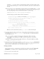
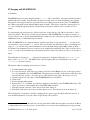
7. You are now ready to initialize FLAMINGOS! This is done by running the command initflam.pl. This
script initializes agents and displays the following windows:
Temperature Daemon - This daemon reads temperatures from two different sensors in FLAMINGOS with
the following output written to the screen:
UFLakeShore208Agent::ancillary
>new reading:(2002:170:05:24:06.920436) 1,75.67 6,82.73
You should always keep an eye on the array temperature ( ~76 K, in the example above where it says
1, 75.67 ) and the MOS dewar temperature (~83 K, where it says 6, 82.73 in the example
above). The array temperature should never vary by more than ~0.5 K. The MOS dewar temperature
must remain below 200 K for sucessful imaging. In normal operation the temperature varies between
~78 K and ~95 K in a sawtooth pattern, depending on the time since the last cryogen fill and the
attitude of the instrument; if you are doing MOS observations, please do not let it warm up above 95
K, as the Decker and MOS wheel mechanisms may bind up. Please contact Dick Joyce, Ron Probst or
Nick Raines if the MOS dewar deviates from this behavior.
Record Temps window - This window logs both temperatures every 10 minutes. It is sometimes easier to
monitor the array and MOS dewar temperatures from here. Please do not close this window or the
associated xterm to which messages are printed; you can minimize the xterm messaging window.
Motor Daemon - This daemon controls the motors which move all of the wheels. If the motor daemon
does not initialize, answer n (for no) to initflam.pl's query about continuing, close the motor
daemon window and run initflam.pl again.
MCE4 Daemon - This daemon runs the array controller, referred to as MCE4. The first time this daemon
is run, if initflam.pl says it is not ready, look at the MCE4 daemon. If it is printing a string of
messages about uninitialized semaphores, quit initflam.pl, close the MCE4 daemon window, and
type ufstop.pl -clean at the 4mguest@flmn-4m-1a prompt. Type control-c after
ufstop.pl has printed several lines of text and has paused without returning the cursor. Then run
initflam.pl once more.
UFSTATUS GUI - This window displays the temperatures, the bias voltage on the array, and the positions
of all of the wheels. Please do not close this window or the associated xterm to which messages are
printed; you can minimize the xterm. Note that it is NOT updated automatically. Rather you must
click the update button in the middle of the GUI for the most recent values and positions. DO NOT
press the update button while any of the wheels are moving.
Array Temperature Quick Look Plot Tool – This GUI will appear, along with an xterm messaging
window. Please do not close this window or the associated xterm to which messages are printed; you
can minimize the xterm. After about 30 minutes there will be ~3 points in the Record Temperatures
log file, and you can hit the Update button to plot the present temperature.
MOS Temperature Quick Look Plot Tool – This GUI will appear, along with an xterm messaging
window. Please do not close this window or the associated xterm to which messages are printed; you
can minimize the xterm. After about 30 minutes there will be ~3 points in the Record Temperatures
log file, and you can hit the Update button to plot the present temperature.
FLAMINGOS@4-m, Ver. 2.34, 2006 Apr 04
Page 9 of 44
During the first execution of initflam.pl, you will be asked at multiple points whether you wish to
continue. In general, if the daemon windows say listening on port, startup has been successful and
you should answer y (for yes). If you are re-running initflam.pl after rebooting MCE4 after a
detector controller crash (cf. § VII. Troubleshooting), but have left the daemons running (which is ok),
the script will complain that the Motor and MCE4 daemons are stalled, however these daemons are
probably functioning properly and you can type y to continue on.
NOTE: The KDE desktops on tan:0.0 and tan:0.1 have available 4 desktops (see the desktop pager on
the toolbar). Once initflam.pl has been run, it is convenient to send the temperature plotting
windows to another desktop. Click on the top bar of the window with the right mouse button and select
the 'send to desktop' command to pick a different desktop.
NOTE: We recommend that one close, and immediately restart, all three daemons (Temperatures,
Motor, and MCE4) once a day. You will also need to close the Record Temperatures Window, and to quit
out of the two temperature quick-look plotting utilities. We recommend that you do this in the afternoon,
e.g., right before starting to take a set of pre-dinner dome flats or darks.
FLAMINGOS@4-m, Ver. 2.34, 2006 Apr 04
Page 10 of 44
III.Nightly Startup Tasks
A. FLAMINGOS Setup
We recommend that you complete the following list prior to each night's observing.
1. Restart all daemons, temperature logging and temperature plotting windows. Please see the notes at the end
of the previous section. The daemons should all be Quit (not Closed, as this just minimizes them), and
initflam.pl immediately re-run, in order to restart the daemons.
2. Fill Both Dewars. At the 4-m the telescope operator should be in charge of filling the dewars with liquid
nitrogen. Both the main dewar (the big one on the bottom) and the MOS dewar (the one on the top) need to
be filled with liquid nitrogen at the start of every night before you can observe, and the MOS dewar also
needs to be filled at the end of every night.
3. Create a data directory for the night on flamingos1a and on nutmeg and start the autocopy script.
From any flamingos1a window:
4mguest@flmn-4m-1a{1} cd /data/4mguest/
Create a directory on flamingos1a with the UT date in the format YYYYMMDD (or whatever
designation you prefer), e.g.:
4mguest@flmn-4m-1a{1} mkdir 2003sep15ut
Create a directory on nutmeg with the exact same name, and make it world writable:
4mguest@flmn-4m-1a{1}
4mguest@flmn-4m-1a{1}
4mguest@flmn-4m-1a{1}
4mguest@flmn-4m-1a{1}
pushd /net/nutmeg/md4/4meter/Flamingos
mkdir 2003sep15ut
chmod a+w 2003sep15ut
popd
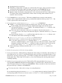
Verify that flamingos1a and nutmeg have enough disk space available. Typing df -h on flamingos1a
shows the following output:
Filesystem
Size
/dev/dsk/c1t0d0s0
9.3G
/dev/dsk/c1t0d0s1
9.3G
/dev/dsk/c1t0d0p0:boot
11M
swap
951M
swap
961M
/dev/dsk/c1t1d0s0
68G
/dev/dsk/c1t0d0s2
16G
nutmeg:/md4
100G
Used Avail Use% Mounted on
1.3G 7.9G 15% /
2.7G 6.5G 29% /usr
1.7M
12K
9.2M
29G
2.5G
30G
9.0M
951M
951M
38G
13G
66G
16%
1%
1%
44%
17%
31%
/boot
/var/run
/tmp
/data
/home
/net/nutmeg/md4
In this example the data disk on flamingos1a, /data, is 44% full, and had 38 GB of available space;
the data disk on nutmeg, /net/nutmeg/md4, is 31% full, and has 66 GB of available space. For
imaging you should ensure that there is at least ≥10 GB of space available; for spectroscopy you
FLAMINGOS@4-m, Ver. 2.34, 2006 Apr 04
Page 11 of 44
should have ~5 GB of space. However, note that the image acquistion scripts will complain on each
and every image if the disk space is is ≥ 93% full, and will refuse to take any more data if the disk is ≥
97% full.
Start the autocopy script. After the image is created on flamingos1a a file with the suffix unlock will
be created. The autocopy script monitors the night directory, and when an unlock file appears it copies
the corresponding image to nutmeg and deletes the unlock file. To start the script:
4mguest@flmn-4m-1a{1} Start.autocopy.4m.nutmeg.sh
An xterm should pop up, with a summary of the above instructions:
--------------------- STARTUP INSTRUCTIONS --------------------1) Create the night's directory on flamingos1a in /data/4mguest
2) Create a directory with the same name on nutmeg, in
/net/nutmeg/md4/4meter/Flamingos
3) chmod a+w the directory created on nutmeg
4) Enter the directory name (not the full path) at the prompt
-------------------- ENDING INSTRUCTIONS ---------------------After the final image has copied to
nutmeg, ctrl-c or close the window.
--------------------------------------------------------------Enter tonight's directory name:
Make sure you enter only the directory name (e.g. 2003sep15ut), and not the entire path.
4. Set up header information, data location, file names. Once you have created a data directory, you need to
tell FLAMINGOS where it is. Run set.filename.pl. This will prompt you to change the parameters
FILEBASE and ORIG_DIR.
FILEBASE sets the root prefix for the image name; all image names will be of the format
filebase.####.fits, where #### ranges from 0001 to 9999; the image number is incremented
automatically.
ORIG_DIR sets the absolute path to the night's data directory. The entry here must have a trailing
slash, e.g. /data/4mguest/2003Mar31/.
5. Verify Position Angle. The value of the parameter ROT_PA in config.mos.dither.pl should match the
actual telescope position angle, which is shown near the bottom of the telescope status screen; the telescope
operator can show you which number to read. The valid rotator range is -0.6º to +180.0º.
B. Startup on the Sky
Several of these steps refer to commands that are described in more detail in section § IV. Imaging with
FLAMINGOS (e.g. for details on how to configure the wheels and how to set the exposure time).
1. Telescope operator's typical nightly tasks:
FLAMINGOS@4-m, Ver. 2.34, 2006 Apr 04
Page 12 of 44
Opening the telescope and dome.
Preliminary pointing check of a bright star on the North Port TV camera. The star should be located
on the grease pencil x-mark on the monitor that corresponds to the FLAMINGOS hot spot.
Focus telescope on North Port TV camera (in direct video mode, not on the guide camera).
Measure seeing. Note that the seeing camera has a focus offset from the best focus on the North Port
TV camera; if the seeing is measured after you have started observing, make certain the focus is
returned to the correct value.
2. Verify FLAMINGOS is set up for imaging. The Decker and MOS wheels should be at their imaging
positions, the Lyot wheel should be at the 4-m stop, and the Grism wheel should be at position open1. The
Ks filter is quite useful for these startup tasks.
3. Center a bright star to within 10 pixels of (x,y) = [1024,1024] on FLAMINGOS.
Within ds9 you can draw rulers from the approximate center of the star to the center of the array.
Double clicking on the ruler line will pop up a GUI with the length of the ruler line and its
decomposition in detector (x,y) coordinates. The starting and ending (x,y) coordinates of the
ruler are also listed and are modifiable.
Enter new values for the center of the star for one endpoint of the ruler, then enter in (1024,
1024) for the center of the array for the other ruler endpoint. Afterwards click the Apply button at
the bottom.
Next, hold and select the Distance pulldown button and choose the Arcseconds distance scale.
The numbers in the window will change accordingly.
Use relative.offset.kpno.pl δ RA δ Dec to offset the telescope.
Note δ RA and δ Dec must be in arcseconds (see the previous step).
Look at the compass arrows in ds9 to determine which of (x, y) corresponds to (RA, Dec); you
may have to darken the display to create enough contrast to see the arrows clearly. At the 4-m the
instrument's default position angle is 90°; under this condition, moving an object from its present
location on the array by (+dx, +dy) in detector space corresponds to (+dDec, -dRA).
Take another image, and iterate with rulers and relative.offset.kpno.pl until the star is
centered.
4. Ask the telescope operator to Zero the telescope pointing.
5. Verify optical alignments. During the first pointing check of the evening, it is advisable to take an image of a
very bright star way out of focus, to verify that the pupil stop has not been moved, and that the mirror covers
and dome are open and positioned properly. You should see a bright donut, with shadows for the secondary
and the spider vanes. If the donut is not circular (e.g., has a sliver missing at the outer edge) there may be
something vignetting.
6. Optimize focus on sky near first target field. The North Port TV camera should have been set up to be
confocal with FLAMINGOS during the first checkout night. You should be able to tune the telescope focus
on the TV camera and be close to best focus on FLAMINGOS. Then you should do a short focus run about
that point (with steps of 50 units) on FLAMINGOS.
Use an exposure time ≥ 10 seconds to average over seeing fluctuations.
We recommend using the tasks in the new flmntools IRAF package written by Anthony Gonzalez (UF) for
assessing image quality. However you can also use the IRAF task imexam, in the standard manner. We
FLAMINGOS@4-m, Ver. 2.34, 2006 Apr 04
Page 13 of 44
detail the use of both here.
The flmntools tasks fwcheck and fwscan take differences of images, and then run SExtractor on
the central 1250 × 1250 pixel region to determine the average FWHM; sources brighter than 10,000
ADU in the difference image are ignored and objects with FWHM < 1.3 pixels are rejected as cosmic ray
hits. To use these, first enter the flmntools package to get the following prompt:
cl> flmn
~~~~~~~~~~~~~~~~~~~~~~~~~~~~~~~~~~~~~~~~~~~~~~~~~~~~
Welcome to FLMNTOOLS - The FLAMINGOS Observing Tools
~~~~~~~~~~~~~~~~~~~~~~~~~~~~~~~~~~~~~~~~~~~~~~~~~~~
Tasks included are:
fwcheck
fwscan
fl>
- Quickly check the fwhm and display the difference image
- Compute the fwhm for each frame in a set of observations
fwcheck
fwscan
This package is used at more than one telescope, so on the off-chance that the parameters have been
unlearned, verify the telescope field is set to Mayall (the 4-m):
fl> epar fwscan
PACKAGE = flmntools
TASK = fwscan
root
=
First
=
Last
=
(telesco=
(mode
=
ugc3371.j
21
25
Mayall)
q)
Root infile name?
First image in set?
Last image in set?
Telescope(MMT,Mayall,KPNO2.1m)?
fwscan takes a range of images as inputs, in the form
fwscan <image root name> <First image number> <Last image number>
It computes running difference images from which it computes the FWHM. You can use this to monitor
the seeing during a sequence of observations. To use this for focus runs, e.g.
4mguest@flmn-4m-1a{1} singleimage.pl
4mguest@flmn-4m-1a{2} relative.offset.kpno.pl 10 0
Ask the operator to increment the focus (e.g 50 – 100 units).
Repeat these three steps as necessary, offsetting the telescope back and forth between each image.
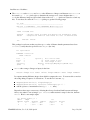
Once you've taken 2 or more images epar fwscan to make certain it is setup for the 4-m, then run
fwscan. Here's some sample output:
fl> fwscan p182e.j 1 9
#Main
Bkgd
#Frame Frame
Average
Median
1
2
0.85'' 0.83''
2
1
0.89'' 0.88''
FLAMINGOS@4-m, Ver. 2.34, 2006 Apr 04
1st
Quartile
0.81''
0.85''
#stars
51
49
Page 14 of 44
3
4
5
6
7
8
9
2
3
4
5
6
7
8
0.82''
0.88''
0.91''
0.79''
0.86''
0.76''
0.82''
0.82''
0.87''
0.92''
0.80''
0.85''
0.76''
0.81''
0.77''
0.81''
0.82''
0.74''
0.79''
0.70''
0.78''
42
45
51
39
48
45
43
fwcheck differences two frames, computes the FWHM, displays the difference frame in buffer 4 of ds9,
and finishes with an imexam cursor on the image. To call it:
fwcheck <image root name> <background image number> <source image
number>
Some notes on using imexam, in the standard manner:
After an image has displayed in ds9 type imexam with no arguments at the cl> prompt2. You can
keep imexam open as you continue to take focus images.
Use the r, a, and e keys to obtain information on the image quality.
We usually use the Moffat fit number (the second fit number from the right after hitting the a or r
keys) for characterizing the image quality.
FWHM of 2 – 2.5 pixels over the entire chip are good enough (0.63 – 0.79 arcsec).
Optimize focus on stars out about 350-500 pixels in radius from the center of the chip.
Stay away from the left edge of the chip, however, as it is slightly more out of focus than the rest of
the array.
7. Variation of focus with temperature. The telescope changes focus due to temperature variations; as the
temperature drops the focus will increase. The relation we have been using is:
∆T(+1 C) = -130 focus units
We frequently monitor the middle dome temperature, but there now is also a truss temperature monitor that
the telescope operator can read for you. It's advisable to watch the temperature every 30 – 60 minutes, and if
necessary adjust the focus on the TV camera.
NOTE: If the focus changes a large amount (2000 units) from one night to the next, verify that the ADC prisms
within the guider are out of the beam. They have been known to move into the beam without being expressly
commanded to do so.
You are now ready to start observing!
2 Note that if you type in the image name, iraf will have to redisplay the image and possibly will not choose a useful
image scaling; it will also disable the scaling buttons in ds9. It is generally better to use ds9's file open in order
to display an image rather than type display in iraf.
FLAMINGOS@4-m, Ver. 2.34, 2006 Apr 04
Page 15 of 44
IV.Imaging with FLAMINGOS
A. Overview
FLAMINGOS may be used for imaging through J-, H-, K-, and Ks-band filters. Sky emission in these bands is
variable and may be bright3. Exposure times are kept reasonably short as a result and guiding is not required.
The general observing procedure is to point the telescope in a dither pattern about the source. FLAMINGOS
has a dither script with several different dither patterns available. They all are oriented in a square grid in (RA,
Dec); the ordering through the pattern is executed in the same psuedo-random order every time (it is not a
raster).
For deep imaging exposure times up to 120 seconds in the J-band, and up to 30 – 90 seconds in the H- and Kbands are common. The shortest possible exposure time used with FLAMINGOS for scripted observing is 2
seconds. There is also a special script which will take a single exposure at the fastest possible exposure time of
1500 milliseconds (mS) immediately upon execution.
N.B.: FLAMINGOS has two integration timers, a milliseconds timer for exposure times ≤ 60 seconds, and a
seconds timer for exposure times ≥ 60 seconds. The seconds timer was determined to have a total timing error
range of ~ 1 second4; the array controller hardware code was updated during August 2003, and this problem
should have been eliminated; however, we have not yet evaluated the engineering data. Some observers choose
to use 60 seconds as the maximum exposure time they will use for their observations, in order to use only the mS
timer.
The default bias for imaging is 1.0 V; the present value may be obtained by hitting the Update All Items
button on the UFSTATUS GUI. The MCE4 array controller supplies this bias automatically on boot, after
initflam.pl has been executed.
The general outline for imaging observations is as follows:
1. Set Instrument Position Angle.
2. For every new target, verify telescope pointing on a SAO or Fixed Bright star close to the target position.
Do so by imaging the star on FLAMINGOS; offset the telescope until it is well centered on the array, then
have the telescope operator Z the telescope (cf. § III. Nightly Startup Tasks: B. Startup on the sky).
3. Acquire target close to the center of the FLAMINGOS field of view (FOV).
4. Check focus.
5. Execute imaging dither pattern.
6. Repeat steps 1 – 5 on standard; we usually use the Persson standards (see the FLAMINGOS binder). The
telescope operator's cache identifies these as HST/NICMOS standards.
7. Take any required dome flats. These may be done in the afternoon.
8. Take darks (~20 each) at every exposure time that was used. These may be done in the afternoon.
The following list of commands is useful for imaging and for spectroscopy (described in the next section). A
more detailed explanation of several of these scripts directly follows the list.
3 In the in the H and K-bands the emission is mostly generated by OH in the atmosphere at elevations of 90 km.
4 Mark Dickinson discovered this problem. See his analysis at: www-int.stsci.edu/~med/flamingos/fewompt_plus.html.
FLAMINGOS@4-m, Ver. 2.34, 2006 Apr 04
Page 16 of 44
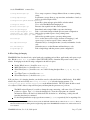
On the FLAMINGOS command line:
config.dither.kpno.pl
config.exposure.pl
Use to setup a sequence of images dithered about a common pointing
center.
Set filename, storage directory, exposure time, and number of reads, as
well as several descriptive fields.
config.filter.grism.decker.wheels.pl
Insert filter, grism and appropriate baffle on decker wheel.
config.mos.wheel
Use to select the MOS wheel imaging hole.
dither.source.kpno.pl
Executes data acquisition in the selected pattern.
fast.singleimage.pl
Immediately take a single 1500 mS exposure time image.
more.singleimages.pl <n>
Take n consecutive images with the present system configuration.
offset.kpno.pl <dra> <ddec> Offset telescope with respect to base pointing center.
relative.offset.kpno.pl <dra> <ddec>
set.bias.pl
set.exposuretime.pl
set.filename.pl
singleimage.pl
Offset telescope with respect to present pointing center.
Use to set the detector bias voltage; shortcuts for imaging (i) and
spectroscopy (s) may be typed to select common values.
Alternative way to set integration time (seconds) and number of reads
only.
Alternative way to set the filename and data directory only.
Take a single image with the present system configuration.
B. Wheel Setup for Imaging
FLAMINGOS has five wheels in its optical path, each containing various filters, pupil masks, and spectroscopic
slits. Hit the Update All Items button on the UFSTATUS GUI to determine the present location of the
wheels. In imaging mode the following configuration should be in place:
!
"
#
$
Decker Wheel (motor a) should be set to imaging.
MOS Wheel (motor b) should be set to imaging.
Filter Wheel (motor c) should be set to one of the following bandpass filters: J, H, K, Ks, JH,
HK.
Lyot Wheel5 (motor d) should be set to 4-m.
Grism Wheel (motor e) should be set to open1.
If all you plan to do is imaging, then the you should not need to adjust the Decker or MOS wheels. If the MOS
wheel is not positioned correctly, use config.mos.wheel.pl to select the imaging aperture. Use
config.filter.grism.decker.wheels.pl to set the indicated wheels. The Lyot wheel should not need
to be adjusted. Each of these scripts will first query and then print the present motor positions.
%
&
The MOS script will query if you wish to change the setup; answering y will cause a list of 17 named
positions to appear. Type 10 to select the imaging hole. Next, the script prints out a detailed
information window, the last bit of which shows the desired move. Answering y at this point will
issue the wheel motion command.
For the filter/grism/decker script, type the motor name (c, d, or a, respectively) before acquiring a list
5 If the power to the motor controller has been cycled, the GUI will claim that the lyot wheel is at Hartmann1. The Lyot
wheel should have been set during the first engineering night of the FLAMINGOS run at the 4-m, and should not need
to be adjusted.
FLAMINGOS@4-m, Ver. 2.34, 2006 Apr 04
Page 17 of 44
of valid positions. Note that position 0 for each wheel is the home position. As with the MOS script,
the script will print out a detailed information window, the last bit of which shows the desired move.
Answering y at this point will issue the wheel motion command.
For both scripts the wheel motion status will be queried approximately every 5 seconds, and the result will be
printed to the screen. It is unnecessary to hit the Update All Items button on the UFSTATUS GUI during
execution of either of these scripts. It is, however, a good idea to update the GUI after the script has
successfully completed.
Note:
'
(
)
It is not possible to move more than 1 wheel at a time.
The only useful dark position is on the grism wheel; there is a dark position on the Decker wheel,
but its use is not recommended.
Once the script has started moving a wheel, do not attempt to abort it. Just wait for it to finish
moving, and run the script once again.
C. Configuring an Exposure
Several parameters need to be set before taking an exposure. The script config.exposure.pl will print out a
list of exposure parameters, and query if you wish to change any of them. If you do, you can step through each
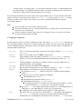
of the modifiable parameters; enter the new value or hit return to keep the old value. Here is a complete list of
parameters that are printed out:
OBS_TYPE
OBJECT
FILEBASE
ORIG_DIR
DATE_OBS
EXP_TIME
NREADS
Type of observation being taken; commonly used descriptors include object, standard,
flat, dark.
Name of object being observed. NOT provided by TCS.
Image filename's prefix; the naming convention is filebase.####.fits where the
numbers (####) are automatically incremented by the data taking script from 0001 to
9999.
Absolute pathname of the directory to which you wish to write data. Make sure you
include the trailing / on the pathname.
UT date at the end of the night (YYYY-MM-DD).
Exposure time for integration in seconds. Must be an integer >= 2 and >= 2 NREADS.
Integer number of non-destructive reads per endpoint per image.
For imaging use NREADS = 1, which corresponds to Correlated Double Sampling
(CDS).
For spectroscopy you can use multiple read sampling:
The minimum value is NREADS = 3.
The maximum recommended value is NREADS = 8.
The minimum allowable EXP_TIME is 2×NREADS.
Note that this script does not always rigorously enforce this condition, so please
double check that EXP_TIME and NREADS are mutually consistent.
For NREADS > = 3 the output image will have signals NREADS times higher than for a
CDS frame; i.e., the output image is a coadd, not a coaverage frame.
A schematic of the readout scheme appears in Figure 3, in the appendices.
The value of the last requested bias is recorded here. 1.0 corresponds to the imaging bias
at 1.0 V; 0.75 V corresponds to the spectroscopic bias where the dark current is
substantially lower even though the well depth is a bit lower than at 1.0 V. To determine
*
+
,
-
.
/
0
1
BIAS
FLAMINGOS@4-m, Ver. 2.34, 2006 Apr 04
Page 18 of 44
WEATHER
WIND
the actual present bias value hit the Update All button on the UFSTATUS GUI.
A numerical descriptor of common environmental conditions (1=photometric, 2=thin
cirrus, 3=broken clouds, 4=overcast, 5=snowing, 6=fog).
A numerical range descriptor of the wind speed (1=calm, 2=low, 3=moderate, 4=high,
5=closed).
After prompting you for all of these parameters, config.exposure.pl will ask if you want to change the
bias. If you do it will automatically run the script set.bias.pl. In imaging mode, the bias should always be
set to 1.0 V.
If you wish to change just the exposure time or the filename, and don't want to run through the entire list of
parameters, then use any of the set.exposuretime.pl or set.filename.pl.
D. Taking Images at a Single Pointing
The most useful script for quickly looking at an image with the present telescope pointing and instrument
configuration is singleimage.pl. This takes an image immediately upon hitting return and displays in ds9.
E. Taking Dithered Images
FLAMINGOS also has the ability to take a sequence of images using a set of pre-determined dither patterns. In
order to configure the dither pattern, run config.dither.kpno.pl. This allows you to change the following
parameters:
DPATTERN
D_SCALE
D_RPTPOS
D_RPTPAT
STARTPOS
USENUDGE
NUDGESIZE
THROW
THROW_PA
The desired dither pattern. Your choices are 2x2, 3x3, 4x4, 5x5, 5box, 5plus, and
45rot_5x5 pattern rotated by 45 degrees. The offsets always are in the form of (δra,
δdec). The 5box pattern is the 2x2 pattern with the central pointing; 5plus is the 5box
pattern rotated by 45 degrees.
Additional scale factor for the offsets. The default of D_SCALE = 1 will add a border to
your images of 15 arcseconds, for a net increase of 30 arcseconds to the total field
of view of the final stacked image, for any of choice of DPATTERN.
Number of times to repeat each dither position.
Number of times to repeat the entire dither pattern.
Starting position in the dither pattern, where 0 is the first position of the pattern. This is
very useful if the system crashes or hangs mid-sequence, however do not forget to reset it
back to 0.
Nudge pointing center on pattern repeats; 0 = do not nudge, 1 = perform nudge.
Radial size in arcseconds of nudge, randomly chosen in one of the cardinal (ra, dec)
directions.
Radial length in arcseconds to other nod beam (not functional in imaging mode).
PA of other beam for nodding (not functional in imaging mode).
After you have configured your dither sequence, run dither.source.kpno.pl to execute the dither pattern
and take images. Immediately after hitting return this script print out information about the requested dither
pattern, and it will ask you to type either HOME or CLEAR before beginning to execute the dither pattern.
If you have any offsets showing on the TCS, typing HOME will cause the script to dither about the pointing
center where the offsets are (0, 0), while typing CLEAR will absorb any offsets present into the current
FLAMINGOS@4-m, Ver. 2.34, 2006 Apr 04
Page 19 of 44
pointing coordinates, and dither about that new position. See the next section on offseting the telescope from
the FLAMINGOS command line.
You can monitor seeing variations and any focus drift if you continuously use fwscan while the dither pattern
executes; just start using it after the first two images have read out.
F. Offseting the Telescope from Flamingos1a
At certain times (such as pointing checks or adjusting the position of your sources on the detector) you may
wish to offset the telscope directly from flamingos1a rather than having your operator do it. To do so use the
following commands:
offset.kpno.pl <RA> <Dec> - Offsets of the telscope in a absolute sense with respect to the
pointing center (where the telescope offsets are (0, 0)). Offsets are in arcseconds and positive values
move the telescope East and North from the pointing center where the offsets are 0, 0. For example,
offset.kpno.pl 5 10 will set the telescope pointing 5 arcseconds East, and 10 arcseconds North.
Repeating this command with the same offsets will not move the telescope.
relative.offset.kpno.pl <RA> <Dec> - Offsets of the telescope relative to wherever the
telescope presently is pointed. Offsets are in arcseconds and positve values move the telescope East
and North from the telescope's current position. In this case, relative.offset.kpno.pl 5 10
will move the telescope 5 arcseonds East and 10 arcseconds North. If the offsets initially were (0, 0)
then after this move they will be (5, 10); repeating this command will move the telescope and the new
net offsets will be (10, 20) arcseconds.
Typing offset.kpno.pl 0 0 will send the telescope back to the starting pointing center.
Typing clear.offsets.kpno.pl will allow you to define the present net pointing (base plus offsets) as the
pointing center. It will cause the telescope to absorb the present offsets, i.e., the offsets on the TCS will reset to
(0, 0) but the telescope will not move.
G. Taking Darks
Darks need to be taken at every exposure time that was used for observation on the sky. Generally 10 – 20
images are taken per exposure time, for averaging; they are usually taken sometime during the daytime. To take
a single set of images at the same exposure time, use the script
more.singleimages.pl <number of images desired>
If the required darks have a long exposure time, consider starting them going as you walk out the door to go to
bed. Be very certain to check on the quality of the data once you get up—the array controller may hang midway
through the data set, or have a glitch which affects some of the images.
If you need to take many darks at several different exposure times, consider writing a cshell (csh) script which
consecutively calls config.exposure.pl and more.singleimages.pl multiple times, each time passing
the proper keystrokes into each script. An example, based on a script written by Anthony Gonzalez (UF),
appears in
FLAMINGOS@4-m, Ver. 2.34, 2006 Apr 04
Page 20 of 44
~4mguest/bin/Example.many.scripted.darks.csh
Note that the blank lines are very important!
Also, be very certain to check later that the script completed successfully; cf. § VIII. Troubleshooting for
possible failure modes, such as bad reads, scrambled images, zero frames, and MCE4 hangs.
FLAMINGOS@4-m, Ver. 2.34, 2006 Apr 04
Page 21 of 44
V.Taking Spectra with FLAMINGOS
A. Overview
FLAMINGOS may be used for obtaining long slit or multi-object slit spectra; please see Section I.
FLAMINGOS + KPNO 4-m Overview for resolving powers within selected passbands. As with imaging, the sky
emission is variable and bright. It is necessary to subtract this contribution from the target spectrum. To this
end, observers generally dither the target up and down the slit. Two modes that we use include walking up the
slit at 5 to 7 different locations, and nodding the telescope back and forth between two offset positions, or
beams, A and B, in an ABBA pattern, symmetrically placed about the target's initial alignment position. Dithering
in an ABBA pattern can be done by hand, or automatically with a script. Walking up or down the slit must be
done by hand.
Telescope guiding is required, as the integration times are generally long, and the time to align a long slit or
MOS plate is also significant. The South Port guide probe (x, y) location is shown on the TCS Video unit.
The radius, r = √(x2 + y2), from the center of the field of view must be ≥100 mm or else the guide probe will
vignette the FLAMINGOS field.
The default bias for spectroscopy is 0.75 V, where the array has lower dark current than at the imaging bias of
1.0 V. The present bias value may be obtained by hitting the Update All Items button on the UFSTATUS
GUI. N.B.: the MCE4 array controller automatically set the bias to 0.776 V on boot, which is not a bias
voltage used in any configuration. The initialization script initflam.pl sets the bias to 1.0 V, and then
queries whether you wish to change the bias. If MCE4 crashes and you have to run initflam.pl, don't forget
to reset the bias for spectroscopy!
The general outline for spectral observations is as follows:
1. Set Instrument Position Angle (PA) to match the slit PA.
2. Verify telescope pointing on a SAO or Fixed Bright star close to target position.
3. Acquire target close to the center of the FLAMINGOS field of view (FOV).
4. Check focus.
5. Acquire a guide star and start guiding.
6. Insert appropriate decker baffle (long slit or MOS) and check its alignment.
7. Insert and align long slit or MOS plate.
8. Insert desired filter and grism.
9. Set bias to 0.75 V for spectroscopy.
10.We recommend that one take quartz or dome flats after the target observations to avoid loss of guiding
which can occur if flats are taken prior to the target observations.
11.Take a junk spectrum.
12.Configure spectral dither pattern parameters.
13.Execute spectral dither pattern.
14.Take all of the required quartz or dome flats, and HeNeAr wavelength calibration data if desired.
15.Repeat steps 1 – 14 with the long slit on a bright telluric standard star (G5-6 V) close by on the sky.6
16.You may want to take a long slit spectrum of an A0 star at low airmass as well.
17.Take darks (~20 each) at every exposure time that was used for flats, wavelength calibrations, science
target spectroscopy, and standard star spectroscopy. Be sure to use the spectroscopy bias of 0.75 V.
6 If you intend to use the 3-pixel MOSplate long slit, you can leave the decker positioned at the MOS baffle.
FLAMINGOS@4-m, Ver. 2.34, 2006 Apr 04
Page 22 of 44
These may be done in the afternoon.
The following list of commands is used for long slit and MOS plate spectroscopy:
On the flamingos command line:
config.exposure.pl
config.filter.grism.decker.wheels.pl
config.mos.wheel.pl
config.mos.dither.kp4m.pl
dither.mos.kp4m.pl
set.bias.pl
tweak.decker.pl <delta_angle>
tweak.mos.pl <delta_angle>
Setup the filename and exposure time.
Use to insert filter and grism and appropriate baffle.
Use to insert long slit or MOS plate.
Setup the spectroscopy ABBA parameters.
Take the spectrosopy ABBA data.
Use to change bias for imaging or spectroscopy.
Allows adjustments to the Decker wheel position.
Allows adjustments to the MOS wheel position.
At the iraf cl prompt:
imexam
xbox
Measure slit profiles and stellar centers (keys: a, x, g, i).
Use to align a MOSplate (keys: q, f, g).
B. Long slit Alignment
1. Set instrument PA before acquiring target.
This must be done first, as the telescope must be at zenith in order to move the rotator.
For safety reasons, have the telescope operator make the rotation from the Cassegrain Cage.
Run config.mos.dither.kp4m.pl, and set the parameter ROT_PA to the new value, so the WCS
compass arrows will display correctly in ds9.
2. Have telescope operator verify pointing on the North Port TV Camera.
Use an SAO star or a Fixed Bright Star near to target field.
There should be a grease pencil mark on the TV monitor indicating where to zero the telescope
pointing.
Take a quick image (2-5 seconds) on FLAMINGOS, and make certain the SAO star is well centered
on the array. If is not, center the star with relative.offset.kpno.pl, then take another image.
Once it is well centered, Z the telescope (cf. § III Nightly Startup Tasks: B. Startup on the sky).
3. Acquire target on FLAMINGOS in Ks filter.
If necessary, adjust telescope pointing with relative.offset.kpno.pl until target is positioned
close to the center of the array.
4. Have the telescope operator adjust focus.
The guide camera should be confocal with FLAMINGOS and should give a good starting focus.
Next, take a series of images over a range that covers best focus, offsetting the telescope between each
image; use relative.offset.kpno.pl and dither back and forth by 10 – 20 arcseconds. Run
fwscan on the stack of images to determine the best focus setting (cf. III. Nightly Startup Tasks, §B −
Startup on the Sky).
Don't spend very long on this, as the focus will change.
Record the middle dome temperature, for reference.
5. Have the telescope operator acquire a guide star, and begin guiding.
Verify that the guide probe radius is greater than 100 mm, in order to avoid vignetting.
6. Take another image with FLAMINGOS, and measure the target's centroid. Use imexam, key a.
7. Insert decker long-slit baffle using config.filter.grism.decker.wheels.pl.
8. Verify decker long-slit is straight along the chip (small dx for a large dy).
2
3
4
5
6
7
8
9
:
;
<
=
FLAMINGOS@4-m, Ver. 2.34, 2006 Apr 04
Page 23 of 44
The easiest way to check the straightness of this wide slit is to draw a ds9 ruler parallel to one edge.
Then double click on the ruler, to find out the angle. It probably should be within 0.05° of 90°.
A more accurate method is to use imexam and j to fit a gaussian to a cross-cut through the slit at two
different y-values. Record the fitted peak (x-coordinate) and the y values, and compute the angle
arctan(dx / dy) if dx is > 1.5 pixel.
You may need to epar jimexam, and set the estimated sigma to 15 pixels, since this slit is very wide.
If dx is > 1 pixel, reorient the decker slit using tweak.decker.pl.
9. Now insert MOS wheel long-slit. Use config.mos.wheel.pl.
10.Verify long slit is straight.
Use imexam, as described in step 8, and measure across the slit with the j key at two different
positions. If dx is > 1 pixel, you should reorient the slit using tweak.mos.wheel.pl.
Don't forget to reset jimexam if you modified any parameters earlier when inserting the decker.
11.Measure x-location of straightened slit, at the location you want to position the star/galaxy.
Use imexam and the j key.
We recommend caution if positioning the target at the center of the array. This is because the last 8
rows of pixels in quadrants 1 and 3 (i.e. (x, y) = [1:1024,1025:1032] and
[1025:2048,1017:1024]) are sometimes corrupted; the rows are parallel to the dispersion
direction. If the distance between the MOS dithering beams is less than 10", one of the two halves of
the spectrum runs the risk of being corrupted.
12.Use relative.offset.kpno.pl to move the star onto the slit.
To quickly estimate the distance to move, draw a large ruler in ds9, and then double click on it to get
its pop-up GUI. Enter the (x, y) coordinates of the star, and the destination position along the slit.
Then click on the Distance pulldown menu, and select Arcseconds.
You may need to iterate with this step, and peak up the flux from the object through the slit.
ds9's display parameters may be adjusted to see the diffraction spikes if the star is quite bright, and
you can tell if the star is well enough centered on the slit; try zmax and log scalings.
We frequently align MOS plates to ~0.15", however note the telescope pointing is finicky for offsets
smaller than 1".
>
?
@
A
B
C
D
E
F
G
H
I
C. MOS Plate Alignment
Mask alignment on FLAMINGOS is done using a modified version of the IRAF task xbox, from the UCSCLRIS
package. A mask should have 2 – 4 boxes (in addition to the slitlets) which correspond to bright alignment
targets. Given an image of the mask, and two files, one containing the approximate locations of the boxes, and
one containing the corresponding star locations, xbox will allow you to quickly determine the translational and
rotational shifts required to center these targets in their corresponding boxes.
It will output translational offsets, in arcseconds, that should correspond to (δ RA δ Dec), and a rotational offset
in degrees. The 4-m instrument rotator is not very precise and cannot be adjusted when not at the zenith, so it
may not be used for the rotational offset. As a result, the MOS wheel must be rotated instead. After every
translation and/or rotation a new image must be taken, and new box and star files generated.
There are 10 important parameters that should be double checked against the complete listing of the xbox
parameters given in Appendix 3. There are three parameters that you may need to change:
1. xsz and ysz
The widths in pixels of the alignment boxes in the x and y directions.
All of the boxes are of the same size.
J
K
FLAMINGOS@4-m, Ver. 2.34, 2006 Apr 04
Page 24 of 44
We typically use alignment star boxes that are 24 – 30 pixels wide. It is very important that this
parameter be set to within a few pixels of the actual values.
L
2. rot_4m
M
This is listed as the 4-m rotation offset, and it should directly correspond to the instrument position
angle. We have experimentally determined that it works for position angle of 90 degrees:
If ROT_PA = 90:
set rot_4m = -90.
N
Running xbox causes a graphics terminal to pop up. It steps through the boxes, in the order listed in the box
file, and presents a cross-cut profile for the x and y directions, along with a red graphics cursor. It will show the
estimated location of the box along the bottom of each cut, along with a horizontal threshold level through the
cut, and a vertical line indicating the estimated location of the peak of the alignment target; the first time through
there likely will be no targets in the boxes, and the line will be centered on a noise peak.
You can adjust the position of this vertical line, say if xbox detects the wrong peak, once the alignment targets
are in their boxes by moving the cursor to the correct location and hitting the f key. Hit q after looking at the
fits for every box, and the final graphical presentation of the estimated adjustments. Afterwards, xbox will print
out a lengthy set of values used for computing the offsets. The final bit of this indicates how much to move the
telescope and rotator. Here is example output from xbox for a plate with ROT_PA = 90 (and rot_4m = -90):
====================================================
*** MOVE TELESCOPE/ROTATOR by the following offsets:
Offset PA by -0.06 (0.01) degree
Offsets: -4.38" (1.09)
30.60" (0.21)
====================================================
The above translational offsets are printed in the order (δ RA δ Dec); also shown are estimated errors.
Translational offsets smaller than 0.5 pixel = 0.16" may be ignored; rotational offsets down to 0.01 degree
probably should be done.
Here is a step-by-step list of how to align the MOS plate:
1. Set instrument PA before acquiring target.
This must be done first, as the telescope must be at zenith in order to move the rotator.
For safety reasons, have the telescope operator make the rotation from the Cassegrain Cage.
Run config.mos.dither.kp4m.pl, and set the parameter ROT_PA to the new value. Now the
WCS compass arrows will display correctly in ds9.
2. Verify that the xbox parameter rot_4m is correctly set for the PA.
3. Have telescope operator verify pointing on the North Port TV Camera.
Use an SAO star or a Fixed Bright Star near to target field.
There should be a grease pencil mark on the TV monitor indicating where to zero the telescope
pointing.
Take a quick image (2-5 seconds) on FLAMINGOS, and make certain the SAO star is well centered
on the array. If is not, center the star with relative.offset.kpno.pl, then take another image.
Once it is well centered, Z the telescope (cf. § III Nightly Startup Tasks: B. Startup on the sky).
If the target field is too faint, or does not have any stars, consider adjusting focus on this pointing
check field (cf. 5 & 6, below).
4. Load the mask design image and region file into buffer 3 of ds9.
O
P
Q
R
S
T
U
FLAMINGOS@4-m, Ver. 2.34, 2006 Apr 04
Page 25 of 44
The images are usually kept in /data/4mguest/Maskfiles/.
Flip and rotate until the image WCS matches that of a raw FLAMINGOS frame.
Turn on tiling, with a vertical orientation; tiling of buffers 1, 2, and 3 is useful. Hide buffer 4.
5. Acquire target on FLAMINGOS in Ks filter.
Set exposure time to pick out aligment targets. Try an exposure time of 10 – 30 seconds if they are
bright, but do not let them saturate. You may need to use much longer itimes (60 – 120 seconds) if
they are very faint.
Attempt to visually pick out the alignment targets (stars or galaxies).
If necessary, adjust telescope pointing with relative.offset.pl until the targets are within the
central region of the array.
If targets are faint, you may need to offset a small amount (20 arcsec) and work on a difference
image. See the comments at the end of this section on how best to do this. Integration times may need
to be increased, too.
6. Have the telescope operator adjust focus on the TV camera,
The guide camera should be confocal with FLAMINGOS, and should give a good starting focus.
Next, take a series of images with FLAMINGOS over a range that covers best focus, offsetting the
telescope between each image; use relative.offset.kpno.pl and dither back and forth by 10 –
20 arcseconds. Run fwscan on the stack of images to determine which focus setting was best (cf. III.
Nightly Startup Tasks, §B − Startup on the Sky).
Don't spend very long on this, as the focus will change.
Record the middle dome temperature.
7. Have the telescope operator acquire a guide star and start guiding.
Verify that the guide probe radius is greater than 100 mm, in order to avoid vignetting.
8. Insert the decker MOS baffle using config.filter.grism.decker.wheels.pl.
9. Verify the decker is straight (check the edge of the decker MOS baffle); use tweak.decker.pl if
necessary (cf. the previous section on long slit alignment).
10.Measure the star centroids and write them to a stars file for xbox:
V
W
X
Y
Z
[
\
]
^
_
`
a
imexam logf=stars keep+
b
Type a on each star
11.Insert MOS plate using config.mos.wheel.pl.
12.Check the plate is straight on the array with by stretching the display to see the plate frames. If it looks
noticably unstraight, use a ds9 ruler to estimate the offset angle and adjust it with use tweak.mos.pl
(cf. the previous section on long slit alignment).
13.Measure the box centers and write them to a box file for xbox. Measure the boxes in the same order
as you measured the stars.
c
imexam logf=box1 keep+
d
type e to generate a contour map
type g to get the graphics cursor
center the cursor on the box and type x
type i to return the image, and repeat this process for the other boxes.
If you cannot see the box well in the contour plot, consider starting over after setting the upper contour
limit threshold to ~5,000 ADU; use epar eimexam and change the upper limit from the default value
of indef.
14.Run xbox:
Type epar xbox
Set the parameter image to the most recent mask image
Set the parameter input = box1(the log filename you used in imexam)
Set the parameter stars = stars (the log filenames you used in imexam)
e
f
g
h
i
j
k
l
m
FLAMINGOS@4-m, Ver. 2.34, 2006 Apr 04
Page 26 of 44
Type :go
An xgterm window with two cross-cut plots through the box, one each for the x and y axes will pop
up.
Type q to step through each of the boxes in the graphics window. If the box center is not clearly
detected, use the f key to force the center, and g to force the signal threshold.
After the last box it will pop up a window showing graphically how much each box must move to
acquire the aligment target. Type q again.
xbox finally will print out how much to rotate the MOS wheel (in degrees) and offset the telescope (in
arcseconds). When xbox is configured for the present 4-m setup, the offsets printed out should
directly correspond to the offsets to type to offset the telescope (see above).
Use relative.offset.pl δ RA δ Dec to offset the telescope.
Use tweak.mos.pl to rotate the MOS wheel by the amount suggested.
Translational offsets > 0.5 pixel ~ 0.2 arcseconds and rotational offsets > 0.01
degrees should be performed.
15.Take another image. At this point you should have stars in boxes. See the following notes on what to do
if the alignment targets are so faint as to require long integrations and background subtraction.
16.Remeasure the boxes with imexam and make a new box file, if a tweak.mos.pl was required previously.
17.Run xbox on the latest image:
Set the parameter image to the new mask image
Set the parameter input to the new box file
Set the parameter stars to be blank
Type :go, and run through each of the graphics windows. Type q if the correct peak has been
detected, otherwise move the cursor to the correct peak, and type the f key to select it.
18.Iteratively repeat steps 12 – 14 until the suggested offsets converge. With experience and some luck, this
procedure should not take more than 15 – 20 minutes.
n
o
p
q
r
s
t
u
v
w
x
y
If the alignment objects are faint, you may need to run xbox on images with some of the sky flux subtracted.
To do this, take an image with no stars in boxes and subtract a scaled version of this image from an image
with stars in boxes:
relative.offset.kpno.pl 0 10 to move stars out of boxes (n.b. you are always guiding after
step 7).
singleimage.pl to generate image sky.0001.fits
relative.offset.kpno.pl 0 10 to move stars back into the boxes.
singleimage.pl to generate image object.0001.fits
z
{
|
}
~
imarith 0.8 * sky.0001.fits scaled.sky.fits
imarith object.0001 - scaled.sky diff.1.fits
now run xbox on diff.1.fits; if you wish to look at it, load it in ds9.
N.B. After every rotation of the MOS plate you must repeat this process of taking a sky image before taking
a new image with the targets in their boxes, because the location of the box has changed on the detector array.
However, if you have not rotated the MOS plate, you can use an old scaled sky image for subtraction.
D. Taking Spectra Once the Slit or MOS Plate is Aligned
There are two options for taking data once the target is aligned onto the long slit or MOS plate. The first option
is to manually perform the dither pattern, taking individual images after each offset. We sometimes do this for
long slit data of calibration stars, if we want to walk the star along the slit in a pattern other than an ABBA
pattern. We frequently use the standard ABBA dither script for the long slit data, and seldom do not use it for the
FLAMINGOS@4-m, Ver. 2.34, 2006 Apr 04
Page 27 of 44
MOS plate data.
Walking up the slit:
We usually move up the slit in steps of 10" for a total of 5-7 positions.
Use singleimage.pl to take an image by hand at every location.
Use relative.offset.kpno.pl to move the star up and down the slit (while continuing to guide).
Setup to execute a dithered ABBA script:
1.
2.
3.
4.
Zero the telescope offsets; type clear.offsets.kpno.pl and type y at the prompt.
Insert filter and grism combination with config.filter.grism.decker.wheels.pl.
Verify bias is set to 0.75 V for spectroscopy when prompted after moving the grism wheel.
Configure filename and exposure time.
For all spectroscopic observations we now recommend taking quartz or dome flats only after the target
observations (cf. Step 8). More details may be found in the next section on calibrations.
5. Take a single junk frame. Set the exposure time to the same exposure time you want to use on your
object. You should do this because the first image taken in low-flux conditions after being in high-flux
conditions has lower counts than normal. For example, the alignment or calibrations might be taken at 30
seconds and the object taken at 300 seconds, so you need to take a junk image at 300 seconds before
taking any real data.
6. Configure the spectral dither sequence using config.mos.dither.kp4m.pl.
Make certain the PA is correct.
Set M_RPTPAT to the number of times to repeat the pattern.
Set M_THROW, the distance in arcseconds between the A & B beams (which are symmetrically offset
about the telescope zero point). For MOS observations we use 4 arcseconds.
If USEMNUDG = 1, the ABBA pattern will be offset along the slit by M_NDGSZ (in arcseconds) on
pattern repeats. For MOS observations we use M_NDGSZ = 0.3. Alternatively, one can execute the
dither sequence with one ABBA pattern at a time, and use relative.offset.kpno.pl and
clear.offsets.kpno.pl before repeating the ABBA pattern. Just keep track of the size and number
of offsets.
7. Start spectral dither sequence, dither.mos.kp4m.pl. Repeat as necessary.
8. Take one or more sets of quartz or dome flats at end of spectral dither sequence (cf. § V. Taking Spectra
with FLAMINGOS: E. Taking Flats and Wavelength Calibrations).
9. Take a long slit spectrum of a telluric absorption star at an airmass at the middle of the dither sequence.
Use a bright star with spectral type G5-6 V.
10.Some observers also take a long slit spectrum of an A0 V star.
E. Taking Flats & Wavelength Calibrations
There are two types of calibrations required for long slit and MOS spectra: wavelength calibration and flat
fields. The 4-m guider/rotator above FLAMINGOS provides a set of quartz and arc lamps for these calibrations.
NOTE: The 4-m calibration projection unit was designed for the RC spectrograph, whose field is smaller than
10 arcmin. Therefore, this does not provide uniform coverage of the entire FLAMINGOS field of view, and
flats/arcs will be significantly weaker at the ends of the mask or slit. In addition, the quartz optics within the
FLAMINGOS@4-m, Ver. 2.34, 2006 Apr 04
Page 28 of 44
projector have absorption bands near 2.3 microns which will show up in the flatfield spectra. Therefore, an
alternative approach to obtaining flats is to observe the inside of the dome using the flatfield lights mounted at
the end of the telescope.
Usually only one set of wavelength calibrations is needed per target; alternatively the OH sky lines may be used
for wavelength calibration, if they are not saturated.
Flat fields should be taken contemporaneously with the target observations: there may be flexure between the
slit and the detector which is dependent on telescope hour angle (HA) and zenith distance (ZD). Additionally, if
one tries to take them at a later time it may not be possible to precisely insert the slit and grism in exactly the
same way as they were when set up on the target. More than one flat field data set may be required if the
observation spans a large enough range of hour angles ( 1 hour, possibly).
We recommend the following:
If the target is a bright standard star, then the observation time probably is short and a single set of
calibrations, taken after the target, should suffice.
If the target is faint, and the time on source is long, take more than one set of flats at several different
hour angles that lie within the same range of hour angles as covered by the science target, but take
them all after finishing the target's observations. For example, if the science target is taken over the
hour angle range from -2:30 and ending at +1:00, then take a set of flats at the final hour angle, then
move the telescope back to an hour angle similar to the initial hour angle, and take another set of flats
(the telescope does not need to be tracking). Or, if you only have time for one set of flats, consider
moving the telescope to the midpoint of the track in hour angle.
The following procedure is used for taking quartz flats with the rotator/guider calibration projector after taking
science target spectra. The alignment of the slit, filter and grism should not have been changed from that used
for the science target. It should take 5 – 10 minutes to complete.
1. Have the telescope operator do the following:
Pause guiding. To do so, just hit the OFF button for the guider.
Turn down the guide camera gain.
Select the Comps mirror position.
Select the Dim Quartz lamp at 100% power.
2. Set filename and exposure time. Use config.exposure.pl.
Integration times of 10 - 30 seconds should suffice for JH-band and HK-band spectroscopy.
Take a test exposure (singleimage.pl). The counts should be <25,000 ADU for wavelengths
< 2.4 microns.
With 30 second itimes, it is possible to do 8 reads, if you can accept the little bit of extra overhead.
3. Take 5 flats with the lamps on. Use more.single.images.pl 5.
4. Have the telescope operator turn down the quartz lamp, or turn it off.
Leave the comp mirror in place.
With flats at two different illumination levels, they can be differenced to remove the dark current.
5. Take 5 flats with the lamps off. Use more.single.images.pl 5.
6. Have the telescope operator turn on the HeNeAr lamp.
7. Take 5 wavelength calibration images. Use more.single.images.pl 5.
Integration times of ~60 seconds should work for JH-band spectroscopy.
FLAMINGOS@4-m, Ver. 2.34, 2006 Apr 04
Page 29 of 44
We usually use only sky lines (OH) for wavelength calibration in the HK-band.
If you wish to resume guiding on the science target for additional observations without rechecking the alignment
(this may or may not work):
1. Have the telescope operator do the following:
Turn off calibration lamps.
Take out the Comps mirror (put it back to the THRU position).
Resume guiding. N.B.:
When guiding is suspended the guide star may move slightly out of the guide box.
Make certain the telescope operator DOES NOT WARP the guide box onto the star to resume
guiding. Doing so will move the guide box to the star's present location, and the telescope will be
guiding at the wrong place, i.e., your target will no longer be optimally aligned on the slit.
If the star has moved out of the guide box, the telescope operator should:
Leave the OFF button pushed on the GUI.
Tweak the telescope pointing with the hand paddle to move the star into the guide box.
Once the star is in the box, resume guiding by pushing the LOCK button on the GUI.
Once the star is again in the guide box, wait a minute to watch the guide software capture the star's
location, and move it back to the guiding center within the guide box.
2. Take a junk image.
To obtain dome flats, position the telescope at the HA midpoint of the target observation (as for the quartz flats).
1. Have the telescope operator do the following:
Turn off telescope tracking and position the telescope at the HA midpoint of the target observation.
Turn off dome tracking
Manually move the dome so that it completely blocks the telescope aperture
Turn on the flatfield projector on the telescope using the Bright lamps at maximum setting
2. Set filename and exposure time. Use config.exposure.pl.
Integration times of 10 - 30 seconds should suffice for JH-band and HK-band spectroscopy.
Take a test exposure (singleimage.pl). The counts should be <25,000 ADU for wavelengths
< 2.4 microns.
With 30 second itimes, it is possible to do 8 reads, if you can accept the little bit of extra overhead.
3. Take 5 flats with the lamps on. Use more.single.images.pl 5.
4. Have the telescope operator turn down the flatfield lamp, or turn it off.
Flats at two different illumination levels can be differenced to remove the dark current.
5. Take 5 flats with the lamps off. Use more.single.images.pl 5.
¡
¢
£
¤
¥
¦
§
FLAMINGOS@4-m, Ver. 2.34, 2006 Apr 04
Page 30 of 44
VI.Shutting Down at the End of the Night
At the end of a long and (we hope!) productive night of observing, there is a small sequence of things that need
to be done. In order, they are:
1. Move the wheels to their resting positions. Using the scripts config.mos.wheel.pl and
config.filter.grism.decker.wheels.pl send the MOS wheel to imaging, the Decker wheel to
imaging, the Filter wheel to J, and the Grism wheel to true_dark.
2. Take any necessary dark frames. Now that the grism is in the dark position, you will be able to take dark
frames. We recommend 10-20 darks per exposure time. Use the set.exposuretime.pl,
set.filename.pl, and the more.singleimages.pl scripts to complete this task.
3. Fill the MOS Dewar (as long as no one is changing MOS plates) - use the same procedure as at the beginning
of the night.
4. Begin writing the transferred data to tape or DVD.
VII.At the End of Your Run
Make certain that you have transferred all of your data to nutmeg, or some other Kitt Peak computer, and written
it to tape or DVD. Although data from all Kitt Peak telescopes is archived, we still suggest that you make all
necessary copies of your data, or back it up on a laptop, before you leave the mountain.
Also, please delete your data from flamingos1a as you leave.
Finally, please do not close any of the FLAMINGOS windows. Leave them open for the next observer, or for
the Kitt Peak Instrument crew, as they will need them open in order to properly shut down FLAMINGOS if they
are doing an instrument change after your run.
We hope you have many clear, sleepless nights, and acquire all the data you desired.
FLAMINGOS@4-m, Ver. 2.34, 2006 Apr 04
Page 31 of 44
VIII.Troubleshooting
1) Problem: The image looks funny. You can see all 32 amplifiers, and the signal level is ~58,000 ADU; the
preceeding or following image(s) has 0 counts.
Solution: This is a hardware problem related to electrical noise causing an early readout of the detector. In
imaging mode MCE4 reads the array once, and then lets it integrate before reading it again (cf. Appendix 2:
Readout Schematic). The final image written to disk is the difference of these two images. This problem occurs
when MCE4 spits out the image before making the second read and difference. There is nothing you can do to
resolve the problem.
Typically, we get bad reads for about 2-5% of the images taken for exposure times ≤ 60 seconds. If you are
getting a much higher failure rate you should call for help
You should be cautious with the image immediately following a bad read frame, because the ADU level in the
image is frequently lower than it should be.
Recently we found that if you get more than two zero frames in a row, then the MCE4 array controller needs to
be rebooted and reinitialized. See the solution to item 4a of the troubleshooting guide for how to do this. N.B.:
the first image taken immediately after rebooting MCE4 also looks like a bad read.
2) Problem: The image looks funny. Various bits of it are scrambled or not in the correct position, or some
bits of it are completely black (0 ADU).
Solution: See if the next image looks normal, if it does keep taking data. If the next image is similarly messed
up, then the MCE4 array controller needs to be rebooted. See the solution to item 4a for how to do this.
3) Problem: Excess Background
Possible solutions:
a) Image a very bright star (V ~ 2) at Ks-band, with the telescope way out of focus, say 2000 units lower.
You should see a donut with a central obscuration and spider vanes. If it's not circular, then you could have
something obscuring the beam---e.g., the dome, the mirror covers, or a mispositioned filter, lyot stop, or Grism
wheel.
b) Check that the ion gauge on the Granville-Phillips pressure monitor is off. When left on it casts a
large amount of warm illumination on the lower right hand corner of the array.
c) Check that the MOS dewar temperature is lower than 200 K. If the temperature is not between 80 – 95
K, did you forget to fill the dewar with LN2? What about the camera dewar?
4) Various Problems related to image readout, wheel motion and iocomm communication.
The three daemons started by initflam.pl (temperature, motor, and MCE4) work by issuing commands to
particular hardware addresses on a networked device called the perle (this used to be the iocomm, but it was
replaced by the perle). This device is like a multiplexer. We have three devices (the temperature monitor, the
FLAMINGOS@4-m, Ver. 2.34, 2006 Apr 04
Page 32 of 44
motor controller, and the MCE4 array controller) which accept commands via serial ports. The perle has one
serial port connection for each device. Commands from the software daemons running on flamingos1a are
received by the perle via an ethernet connection, and then passed to the correct device.
Troubleshooting several types of problems involves deciding if the problem is intrinsic to the device, or to the
communication via the perle itself.
a) Problem: The image has not read out. The exposure time counter never appears.
Sometimes the array controller crashes before the image acquisition script issues the START command to
MCE4. For example, a successfully started image acquistion should show:
/usr/local/uf/bin/ufdc -host flmn-4m-1b -port 52008 -acq "start -timeout
9 -cnt 1 -lut /usr/
local/flamingos/flamingos.headers.lut/Flamingos.lut -fits
/usr/local/flamingos/flamingos.hea
ders.lut/Flamingos.fitsheader -file /data0/4mguest/Test/test -index 2"
If it hangs here for more than ~6 seconds, type ufdc -q status in
another flmn-2m-1b window
ufdc> greeting: UFGemMCE4Agent -- accepted client: ufdc@flmn-2m1b@2002:350:03:40:49.170980
2002:350:03:40:49.170980
2002:350:03:40:50.440745ufdc@flmn-2m-1b
START
GATIR *Flamingos Beta* 2.00_f.07 >>
>>>>>.....TAKING AN IMAGE OR APPLYING LUT.....
(Exposure time + number of reads = 3 + 1)
Have slept 3 seconds out of an exposure time of 4 seconds
If you do not see the START command and the exposure time counter above, then MCE4 has crashed.
The statement in the output above that saying to type ufdc -q status is a red herring, doing so will
not change anything.
Solution: Reboot MCE4 and reinitialize it with initflam.pl. To reboot MCE4 telnet to baytech from
flamingos1a with userid mce4pow and password ________. Type reboot 1, and wait for the prompt to
return. Then type logout. Example output from this procedure follows:
4mguest@flmn-4m-1b{2001}telnet baytech
Trying 140.252.53.86...
Connected to baytech.
Escape character is '^]'.
RPC-3 Telnet Host
Revision F 4.20a, (C) 1999
Bay Technical Associates
Unit ID: flmn-4m-1b
Enter username>mce4pow
Enter password>_________
Option(s) installed:
True RMS Current
FLAMINGOS@4-m, Ver. 2.34, 2006 Apr 04
Page 33 of 44
Internal Temperature
True RMS current:
Maximum Detected:
1.6 Amps
1.7 Amps
Internal Temperature: 18.5 C
Circuit Breaker: On
Selection
Number
1
Outlet
Name
mce4
Outlet
Number
4
Power
Status
On
Type "Help" for a list of commands
RPC-3>reboot 1
(Now it counts down for 10 seconds before applying the power).
..RPC-3>logout
Now run initflam.pl at the flamingos1a prompt. You do not need to close any of the daemons to
rerun initflam.pl for this problem. At the start, initflam.pl will complain that the motor and
mce4 daemons are not up and listening, and ask if you want to continue. You do want to continue, as the
daemons were working properly before the crash of MCE4. MCE4 must be reinitialized, in order to set
the proper clocking of the array. If you were taking a spectrum, you need to reset the bias to 0.75 V.
After it has successfully initialized the EDT frame grabber (where it says “do you see 10 lines of text
between a line saying opening pdv unit 0 and a line saying done”), it will ask if you want to
continue. You can type y at this point.
Next, you need to take two junk frames with short exposure time (e.g., 3 seconds). The first frame after
repowering and initializing MCE4 will look like a bad read; however, the second frame should look
normal.
b) Problem: The image will not read out. A communication error message appears.
The following error message appears during the integration:
UFClientSocket::connect> unable to connect to flmn-4m-1a, port #
52008Connection refused
ufdc> unable to connect to MCE4 command server agent...
Solution: The fiber optic serial communications between the perle and the MCE4 controller may have
been switched off inadvertently. There are two fiber converter units, one below the MCE4 controller on
the left-hand rack, the other below the perle on the right-hand rack (Figure 2, below). Each has two small
toggle switches, which must be set so that the red and green LEDs are OFF. The LEDs are used only for
testing that the fiber is working.
FLAMINGOS@4-m, Ver. 2.34, 2006 Apr 04
Page 34 of 44
Figure 2. Fiber optic converter boxes below MCE4 (left panel) and below perle (right panel)
c) Problem: The image acquisition counts past the exposure time without reading out an image.
Solution: This problem rarely happens anymore. With our previous slower version of flamingos1a, it
would sometimes take an extra 5 to 10 seconds to finish reordering the pixels, i.e., applying the look up
table, or LUT, before it writes the image to disk. In the MCE4 daemon window you sould see string of
dots being printed out during the apply lut phase:
UFEdtDMA::applyLut>
.
.
.
.
.
.
.
.
.
.
You should watch for several seconds to see if this line is present, and that it is printing additional dots.
When it finishes, it should also print something similar to:
UFEdtDMA::takeAndStore> close mmap file:
/data/4mguest/Test/test.0002.fits
UFEdtDMA::> completed: 1 -- /data0/4mguest/Test/test.0002.fits
ufgtake> acquired frames: 1
UFEdtDMA::takeAndStore> close mmap file:
/data/4mguest/Test/test.0002.fits
UFEdtDMA::> completed: 1 -- /data0/4mguest/Test/test.0002.fits
ufgtake> acquired frames: 1
If this never appears, try typing ufstop.pl -stop -clean at a flamingos1a prompt. Then try taking
another image; if that fails see if ping perle returns with the message that the perle is alive. If the
perle is alive, try rebooting MCE4 and reinitializing. If that completely fails, call for help.
d) Problem: A large number of error messages are printed out either when trying to move a wheel (e.g.,
with config.filter.grism.decker.wheels.pl), or during the first part of an image
acquisition, where it sends commands to MCE4.
Solution: It's possible that the perle (formerly, iocomm) has crashed, or is very confused. Try ping
perle from flamingos1a; if there is no response, it needs rebooting. Even if there is a response, it may
be advisable to reboot it. To do this telnet baytech, userid perlepow password ______. At the
prompt type reboot 1, and then type logout when the prompt returns (e.g., see the example output in
3a, above). Now you must close all three daemons (Temperature, Motor, and MCE4) and the
record_temperatures window and run initflam.pl.
5) Problems when running config.filter.grism.decker.wheels.pl or config.mos.wheel.pl. The script ends by
FLAMINGOS@4-m, Ver. 2.34, 2006 Apr 04
Page 35 of 44
saying that the time for the wheel's motion to complete has expired.
The default algorithm for motion of the wheels is that they first go to the home position, tell the controller
to zero the position, and then move to the demanded position. We refer to this as a home-type of limit, or
limit switch. We usually run the MOS wheel in an alternative mode refered to as a home-type of nearhome. In this mode the wheel moves from the present position back to somewhere close to home, and
then to the demanded position.
There are two modes of failure for each wheel.
(1) The limit switch fails to engage. If the wheel operates with a limit-switch home type, then the
wheel can spin endlessly, and the perl script will just give up after some time limit. If you can stop
the wheel and determine the location of the mechanism, it is possible to recover from such a failure
and then use the near-home motion algorithm for the wheel.
(2) The wheel binds, and a grinding noise is audible if you stand next to the dewar. If this happens
there usually is no quick recovery after you have stopped the motor.
Solutions:
A) First, you must stop the wheel that is either spinning endlessly, or is jammed.
1. Type ctrl-Z, type jobs, kill -9 %<jobnumber> if the perl script has not yet finished and
you already know that there is a problem.
2. Type ufmotor -host flmn-4m-1a -port 52004
a) At the motor prompt, type <motor_name>@, where <motor_name> is one of letters a, b,
c, d, or e, where motor a = decker, b = mos, c = filter, d = lyot, and e = grism. This should do
a soft-stop of the motor.
b) Type exit to quit ufmotor.
3. Type turn.off.motor.hold.current.pl
If this does not stop the motion of the wheel (e.g., you can hear it spinning, or grinding), the last
recourse is to turn off the motor controller itself. Note: any wheels that use near-home type and
are not at home will be lost when the motor controller is powered up again. You should call for
assistance if this happens. To do cycle the power on the controller, telnet baytech as
motorpow, password ______, and then reboot 1, and logout to exit.
B) If the failure was of the limit switch, you need to recenter the mechanism in question, and
redetermine the home point. The best way to do this is to image a very bright star with the telescope out
of focus by about 3000 units. The wheel probably is not well centered, so use one of the tweak scripts
to adjust it (there are special engineering tweak scripts, in addtion to the ones for the decker and MOS
wheels). Then step the wheel by discrete positions, and measure the background. With some help you
should be able to determine where you are, and use the ufmotor command to rezero everything.
FLAMINGOS@4-m, Ver. 2.34, 2006 Apr 04
Page 36 of 44
IX.Contacts & Further Information
1. Dick Joyce, Ron Probst, and/or Nick Raines will help new observers during their first night of observing with
FLAMINGOS at the 4-m. If simple questions arise during the run, please address them first to Dick or Ron,
and then to Nick. Their contact information is listed below.
Richard Elston, University of Florida, FLAMINGOS PI
office: 352-392-2052
[email protected]
Nick Raines, University of Florida, FLAMINGOS support scientist
office 352-392-2052, ext. 244
home: 352-381-9069
[email protected]
Dick Joyce, NOAO Friend of FLAMINGOS
office: 520-318-8323
home: 533 (from mountain)
[email protected]
Ron Probst, NOAO Friend of FLAMINGOS
office: 520-318-8268
home: 521 (from mountain)
[email protected]
2. Updates to this manual and other manuals, and more information, may be found on the web:
Kitt Peak/NOAO web site
University of Florida
www.kpno.noao.edu/manuals/flmn
www.flamingos.astro.ufl.edu/index.html
www.flamingos.astro.ufl.edu/Manuals/
Richard Elston's web page www.astro.ufl.edu/~elston/flamingos/home_frame_set.html
3. In the event of a power outage for which the mountain does not switch to generator, please contact the
mountain staff about properly shutting down the FLAMINGOS computers (flamingos1a & flamingos1b).
There is a shutdown manual available off of the Manuals web page, but the procedure requires someone with
root access (e.g. the mountain staff, or anyone on the list above).
X.Acknowledgements & Other Bits
This version of the manual is substantially more complete from previous versions. Information has been
incorporated from previous versions written by Katherine Wu, and Richard Elston and Elizabeth Lada. Helpful
suggestions, comments and questions came from (in no particular order): Joanna Levine, Michael Ledlow, Jay
Elias, Ron Probst, Dick Joyce, Mark Dickinson, Peter Eisenhardt, and Dan Stern.
Written in StarOffice 6.0, a nice program, but with a buggy Postscript driver. To generate a good
Postscript version of this document: (1) print to file, (2) run ps2pdf12, Ver. 6.52 to convert it to PDF, (3)
finally run xpdf, Ver. 2.33 to generate sane Postscript that actually will print.
FLAMINGOS@4-m, Ver. 2.34, 2006 Apr 04
Page 37 of 44
Appendix 1: FLAMINGOS Command Listing and Partial Description of Function
A. Basic Instrument Configuration Commands
config.exposure.pl
Sets object, filebase, orig_dir, exp_time.
config.filter.grism.decker.wheels.pl
config.mos.wheel.pl
initflam.pl
set.bias.pl
set.exposuretime.pl
set.filename.pl
Setup and move Filter, Grism and Decker wheels.
Setup and move the MOS wheel.
Starts daemons and setup MCE4 array controller.
Imaging use bias = 1.0 V; Spectroscopy use bias = 0.75 V.
Exposure time is in integer seconds; 2 seconds is the shortest.
Set image's rootname and directory.
B. Basic Imaging Configuration and Acquistion Commands
config.dither.kpno.pl
dither.source.kpno.pl
fast.singleimage.pl
more.singleimages.pl #
singleimage.pl
Select dither pattern and number of repeats.
At present, only dithers on source in a square grid.
Automatically take a 1500 mS exposure time image.
Takes # of images with parameters set by config.exposure.pl.
Automatically take an image with present integration parameters.
config.dither.strip.kpno.pl Used to setup a running strip of square dithered images.
dither.strip.clear.kpno.pl Takes a running strip of square dithered images.
C. Basic Spectroscopy (MOS and Long Slit) Configuration and Acquisition Commands
config.mos.dither.kp4m.pl
dither.mos.kp4m.pl
set.new.mos.plate.names.pl
Setup the spectroscopy ABBA parameters, including position angle.
Take the spectrosopy ABBA data
Use when loading new MOS plates so their names are in the header.
D. Advanced Imaging and Spectroscopy Commands
config.chippa.kp4m.pl
For setting the chip PA on the sky.
config.slit.chip.pa.kp4m.pl For setting the PA of the slit wrt the chip.
E. Telescope Information and Motion Controller
clear.offsets.kpno.pl
offset.kpno.pl
relative.offset.kpno.pl
wcsinfo.pl
Absorb present offsets into the present position; offsets now 0, 0.
Absolute offset wrt pointing center of telescope.
Offset telescope wrt the present offsets.
Request the present TCS information.
FLAMINGOS@4-m, Ver. 2.34, 2006 Apr 04
Page 38 of 44
F. Resetting the Array Controller (MCE4), the Motor Controller, and the Iocomm
From flamingos1a:
1. telnet baytech
userid:
mce4pow, motorpow, or perlepow
password: __________
(For telnet from a Kitt Peak machine, the baytech's name is flmn-4m-p).
2. reboot 1
3. logout
4. If you rebooted the perle, close all daemons (the TEMPS, MOTOR, and MCE4 xterm windows),
otherwise leave them open.
5. initflam.pl
G. Data Transfer and Data Compressing, Data Taping & DVD Burning
Data are written to disk on flamingos1a automatically. At the start of every night you should run a special
script (see below) which will automatically copy the data to nutmeg. Once the data start arriving on nutmeg,
and before writing data to tape or to a DVD, we recommend that you compress the data using gzip (we
usually compress the data as a step separate from the tar command if we are writing tapes).
If you change the file prefix frequently throughout the night, consider incrementally gzipping the transferred
data; gzip is usually pretty slow, so this will give you more time in the afternoon for archiving the data.
Whatever you do, do not gzip the data on flamingos1a as you are taking data, because it will slow down data
acquisition.
Instructions for moving data from flamingos1a to nutmeg:
¨
Run Start.autocopy.4m.nutmeg.sh at the start of the night in order to background copy the data to nutmeg.
Common commands used for writing tapes with the DDS4 tape drive on nutmeg:
©
ª
«
¬
mt -f /dev/nst0 status
mt -f /dev/nst0 fsf #
mt -f /dev/nst0 rewind
mt -f /dev/nst0 offline
tar -cvf /dev/nst0 night1.dir/
Burning DVDs:
1. From a nutmeg terminal, type dvdrecord -scanbus. Examination of the output should show a Pioneer
DVD-RW burner on dev=2,0,0.
2. Use mkisofs -R -J -o night.iso night/ to make an iso file (see the appendis in the manual on
burning DVDs). Note: a DVD will hold ~ 4.3 GB of data, which is ~265 FLAMINGOS images.
3. Use dvdrecord -dao dev=2,0,0 night.iso to burn the DVD.
4. When it finishes, use mount /mnt/dvdrom and ls /mnt dvdrom to inspect the files on the DVD.
When complete, cd out of /mnt/dvdrom and umount /mnt/dvdrom and then eject /mnt/dvdrom
to eject the DVD.
FLAMINGOS@4-m, Ver. 2.34, 2006 Apr 04
Page 39 of 44
H. Instrument Engineering Commands
center.of.rotation.pl
config.location.pl
Determine the center of rotation from 3 points.
Copies the correct Flamingos.fitsheader for a telescope.
engineering.config.home.type.wheels.pl
Sets Limit Switch or Near Home wheel motion.
engineering.config.mst.pl
Sets milliseconds vs. seconds timer usage.
engineering.config.output.pl
Various settings (unlock file, talk to TCS, png image, etc.).
engineering.ct10.singleimage.pl Output the first read of a CDS read.
engineering.ct12.singleimage.pl Output the first set in a multiple read.
engineering.ct17.pl
?
engineering.ct40.takecnt.pl
?
engineering.more.ct10.pl
Takes multiple CT 10 frames.
engineering.more.ct17.pl
Takes multiple CT 17 frames.
engineering.set.lyot.wheel.pl
Moves Lyot wheel for each telescope.
engineering.soft.stop.mos.wheel.pl
Sends and escape character to the MOS wheel controller.
engineering.tweak.filter.wheel.pl
Allows adjustments to the filter wheel position.
engineering.tweak.grism.wheel.pl
Allows adjustments to the grism wheel position.
engineering.tweak.lyot.wheel.pl Allows adjustments to the lyot wheel position.
readFITheader.pl -f /usr/local/flamingos.headers.lut/Flamingos.fitsheader
turn.off.motor.hold.current.pl
tweak.decker.pl delta_angle
tweak.mos.pl delta_angle
ufidle.pl
ufstop.pl -clean
ufstop.pl -stop
FLAMINGOS@4-m, Ver. 2.34, 2006 Apr 04
Prints out the present fitsheader template file for the next image.
Sends command to filter, lyot and grism wheel controllers.
Allows adjustments to the decker wheel position.
Allows adjustments to the MOS wheel position.
Sets MCE4 in continuous resetting mode on the array.
Sets various semaphores in /var/tmp/
Stops the present integration.
Page 40 of 44
Appendix 2: Readout Schematic
Figure 3 Array Readout Timing. All 4 quadrants of the array are read out simultaneously; within one quadrant all 8
amplifiers are read out, with pairs of amplifiers multiplexed down into one A/D input. Thus in a frame time of 1.33
seconds 1024 × 256 pixels are read out. The image delivered by MCE4 for a CDS frame is the difference image from
two nondestructive reads of the array; the timing for a CDS frame with integration time of 6 seconds is shown. Note
that the total time to take this frame is 6 + 1.33 seconds, but the net integration time for all pixels is 6 seconds. The case
for 3 multiple reads is also shown. For a 6 second integration this takes ~10 seconds. MCE4 delivers the difference
image of the sum of each set of 3 reads. Thus the final image with multiple reads is a coadded image; the pixel values
will be 3 times larger than that obtained with a CDS read.
FLAMINGOS@4-m, Ver. 2.34, 2006 Apr 04
Page 41 of 44
Appendix 3: XBOX Default Parameter List for Instrument at PA = 90 degrees
PACKAGE = ucsclris
TASK = xbox
image
input
(stars
(nxbox
(nybox
(xsz
(ysz
(fwhm
tel
(rotdir
rot_2m
xrot_2m
yrot_2m
invert2m
rot_4m
xrot_4m
yrot_4m
invert4m
MMT_rot
MMT_xrot
MMT_yrot
MMT_inve
GemS_rot
GemS_xro
GemS_yro
GemS_inv
(xoff
(yoff
(def_ref
(def_err
(niter
(box_siz
new_x_fw
new_y_fw
vmag
wt
(coord
(mode
=
=
=
=
=
=
=
=
=
=
=
=
=
=
=
=
=
=
=
=
=
=
=
=
=
=
=
=
=
=
=
=
=
=
=
=
=
=
target.0001
image
box1
input file (box locations)
) file of star centroids, using 'a' key in imexam
50
) nx of extraction box
50
) ny of extraction box
30.
) x box length (pixels @ .15mm/pix)
30.
) y box height (pixels @ .15mm/pix)
4.
) star FWHM in x (pixels @ .21''/pix)
4m
Telescope - 2m,4m,MMT or GemS
-1
) Enter rotator direction (1,-1)
90.
Enter 2m rotation offset
1162.
Enter 2m center of rotation x
-1868.
Enter 2m center of rotation y
no
Enter if 2m field is flipped (yes/no)
-90.
Enter 4m rotation offset
1162.
Enter 4m center of rotation x
-1868.
Enter 4m center of rotation y
yes
Enter if 4m field is flipped (yes/no)
90.
Enter MMT rotation offset
1024.
Enter MMT center of rotation x
1000.
Enter MMT center of rotation y
yes
Enter if MMT field is flipped (yes/no)
0.
Enter Gemini South rotation offset
1009.
Enter Gemini South center of rotation x
989.
Enter Gemini South center of rotation y
no
Enter if Gemini South field is flipped (yes/no)
0.
) add'n. x shift to apply (pix)
0.
) add'n. y shift to apply (pix)
0.2
) default error estimate
0.2
) default error estimate
6
) number of iterations in fit
0.5
) box half-len (usually acceptable resid)
4.
[Enter new x FWHM]
4.
[Enter new y FWHM]
100.
[magnification factor]
1.
[weight]
)
graphics cursor input
ql
)
FLAMINGOS@4-m, Ver. 2.34, 2006 Apr 04
Page 42 of 44
Appendix 4: Additional Notes on MOS Plates
An example MOS plate for use at the 4-m is shown adjacent, in Figure 4. It
is approximately full size (~105 mm in length).
The sizes of the slits and alignment boxes are the same size in pixels for both
telescopes.
The slitlets are 3 pixels (0.9" at the 4-m) wide, with a minimum length of
approximately 30 to 40 pixels (9" to 12" at the 4-m).
The alignment boxes are 25 to 30 pixels (7.5" to 9" at the 4-m) on a side.
We usually try to find guide stars with K magnitudes in the range 11–13.
Figure 4—Example MOSplate.
The view of the MOS wheel, from the side that will be seen when loading is presented on the next page. Copy
or download and print it ( http://flamingos.astro.ufl.edu/Manuals/), and then annotate it as you
load the plates.
Critical annotation items include (see Figure 3):
®
¯
°
±
Plate name or ID
Rotator Position Angle for proper plate orientation on the sky
Slit Width, in pixels
Compass, with sky parity showing the orientation of North and East
After the wheel is back in the MOS dewar, and the dewar is on the pump, run the script
set.new.mos.plate.names.pl, so that the plate name makes it into the FITS header when the plate is
selected.
FLAMINGOS@4-m, Ver. 2.34, 2006 Apr 04
Page 43 of 44
Appendix 4: Additional Notes on MOS Plates: A Figure of the MOS Wheel, Useful When Loading Plates
MOS Position PA
B
______
D
______
F
______
H
______
K
______
L
______
Name
____________________
____________________
____________________
____________________
____________________
____________________
MOS Position PA
M
______
N
______
O
______
P
______
Q
______
Name
________________
________________
________________
________________
________________
Telescope: ___________________________________
Date Loaded: _________________________________
Observing Program: ___________________________
FLAMINGOS@4-m, Ver. 2.34, 2006 Apr 04
Page 44 of 44