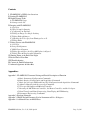
1
I. FLAMINGOS + KPNO 4-m Overview
FLAMINGOS is the FLoridA Multi-object Imaging Near-ir Grism Observational Spectrometer. This manual
provides the user with a good portion of the tools needed to successfully take data with FLAMINGOS at the
KPNO 4-m telescope. A knowledge of basic unix commands is assumed.
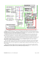
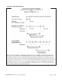
FLAMINGOS is comprised of two cryogenic dewars. The MOS dewar, closest to the telescope backplane,
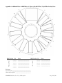
contains a wheel which can position 11 slit plates in the Cassegrain focal plane. The Camera dewar,
immediately following the MOS dewar contains all of the powered optics, filters, stops, grisms, and the detector
array. A functional diagram showing the relative layout and connections to the various electronics is shown in
Figure 1.
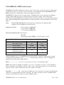
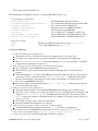
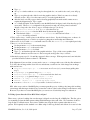
Array:
Hawaii II 2048x2048 HgCdTe science grade array, divided into four quadrants with 8
amplifiers each (32 amplifiers for the whole array).
Linearity at 1.0V bias:
0.5% non-linear at 25,000 ADU
2% non-linear at 35,000 ADU
>3% non-linear at 40,000 ADU
Plate Scale and Field of View: 0.316"/pixel
10.8' FOV
Typical image quality (FWHM) = 2–3 pixels = 0.63" – 0.95".
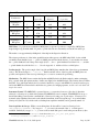
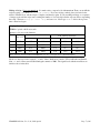
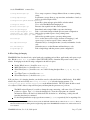
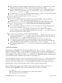
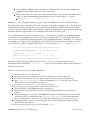
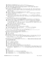
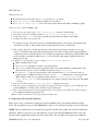
Detector Characteristics:
Imaging
Spectroscopy
1.0
0.75
~50,000
~38,000
Target Count level (ADU)
25,000 – 35,000
15,000 – 20,000
CDS Read Noise without
Differential Amplifier (e)
~40
~40
Gain (e / ADU)
~4.9
~4.1
Bias Voltage (Volts)
Full Well (ADU)
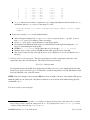
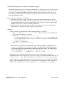
N.B. The default bias on boot of the MCE4 array controller is 0.776 V, which is not used in any observing
configuration; the initialization script initflam.pl automatically sets the bias to 1.0 V for imaging, but
queries the user if they wish to change the bias.
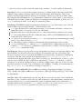
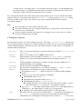
Filters: J, H, K, Ks, JH (0.9 µm – 1.8 µm), and HK (1.25 µm – 2.5 µm) bandpass filters.
Grisms: Two grisms are available, covering the JH (0.9 µm – 1.8 µm) and HK (1.25 µm – 2.5 µm) bandpasses.
The HK grism may be used with the HK filter to obtain H- and K-band spectra in first order, or it may be used
with the JH filter to obtain H-band in first order, and J-band in second order.
Long Slits: 2, 3, 6, 9, 12, and 20-pixel slits are available; the 3 and 6 pixel slits cover much of the chip but the
others slits cover approximately two-thirds of the chip. All of these long slits are located on the MOS wheel.
An extra 3-pixel long slit is located in one of the 11 MOS positions.
FLAMINGOS@4-m, Ver. 2.34, 2006 Apr 04
Page 3 of 44