1
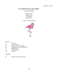
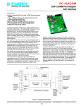
Starter Kit and User Manual for the
HelloDevice 1100
Version 1.1
Starter Kit and User Manual for the HelloDevice 1100
Version 1.0
Last revised on July 16, 2000-07-16
Printed in Korea
Copyright
Copyright 2000, Sena Technologies, Inc. All rights reserved.
Sena Technologies reserves the right to make changes and improvements to its product without providing notice.
Trademark
HelloDevice™ is a trademark of Sena Technologies, Inc.
Windows® is a registered trademark of Microsoft Corporation.
Ethernet® is a registered trademark of XEROX Corporation.
Notice to Users
When a system failure may cause serious consequences, protecting life and property against such consequences
with a backup system or safety device is essential. The user agrees that protection against consequences resulting
from system failure is the user's responsibility.
This device is not approved for life-support or medical systems.
Changes or modifications to this device not explicitly approved by Sena Technologies will void the user's
authority to operate this device.
Company Address
Sena Technologies, Inc.
210 Yangjae-dong, Seocho-gu
Seoul, Korea 137-130
Telephone: +82-2-573-7772
Fax: +82-2-573-7710
Email: [email protected]
Website: http://www.sena.com
Table of Contents
1. Before You Start
2. Overview
3. Main Board Specifications
3.1. Power Supply
3.2. Microprocessor
3.3. Ethernet Interface
3.4. Digital I/O Interface
3.5. Flash Memory
3.6. Firmware
4. Setting Up the Hardware
4.1. Installing Utility Software
4.2. Connecting Hardware
4.3. Configuring Network
5. Quick Tour
5.1. Building a Homepage
5.2. I/O Control Demo Using Demo Board
6. Connecting User Devices
6.1. Communication Protocol
6.2. Implementing Hardware
6.3. Sample Programs
Appendix A. IP address configuration by using cross-over Ethernet cable
Starter Kit and User Manual for the HelloDevice 1100
1. Before You Start.
§
Items supplied in the HelloDevice 1100 Starter Kit
Items
Hardware
Software
Piece(s)
HelloDevice 1100 Main Board
1
5V Switching Mode Power Supply (SMPS) or Power Adaptor
1
Demo Board for I/O Control
1
Cable for I/O Control (20 pins, 2.5mm pitch)
2
HelloDevice Utility Software and Sample Demo Program
(Download the latest version at http://www.sena.com)
User Manual
§
§
1
1
Operating Environment
−
Voltage Supply = 5V DC ±10%
−
Current Supply = 200mA or lower
−
Operating Humidity = 0 ~ 95%
−
Operating Temperature = 0 ~ 50 Degrees Centigrade
Technical Support
Sena Technologies, Inc.
210 Yangjae-dong, Seocho-gu, Seoul, Korea 137-130
Phone: (+82-2) 573-7772
Fax: (+82-2) 573-7710
Email: [email protected]
http://www.sena.com
1
Starter Kit and User Manual for the HelloDevice 1100
2. Overview
The HelloDevice is a connectivity solution that allows any device in any industry to communicate over any
network, using any interface. The HelloDevice 1x00 product family is a board-level Ethernet controller that lets
manufacturers and system integrators connect devices such as home appliances and industrial control systems
directly to the Internet via Ethernet, and remotely communicate with and control them with standard web
browsers such as Microsoft Explore and Netscape Navigator. The HelloDevice 1x00 product family is
categorized into three types depending on how the HelloDevice connects to a user device:
§
Digital I/O communication module (HelloDevice 1100)
§
Dual-port RAM communication module (HelloDevice 1200)
§
Serial communication module (HelloDevice 1300)
Table 2.1 shows the basic specifications of the HelloDevice 1x00 Series.
Model
Basic Spec.
HelloDevice 1100
HelloDevice 1200
HelloDevice 1300
Scenix Sx52BD
(8 bits microprocessor, 50 MIPS)
512 Kb flash memory
(Saves user Web files)
CPU
Memory
Network
Connection
10 Base-T Ethernet Interface (IEEE802.3)
Connection to the
User device
Internet Protocol
Support
Utility Software
16 contact points digital
1 channel
input
2 KB dual port RAM
RS-232/485
16 contact points digital
Max. 38,400 bps
output
HTTP1 / SMTP / BOOTP
TCP / UDP
IP / ICMP / ARP
Ethernet (IEEE802.3)
HelloDevice utility software (for Windows 95/98/NT/2000 platform)
: IP addressing and Web page uploading
Table 2.1 Basic specifications of the HelloDevice 1x00
1
Currently, HTTP 1.1 specifications are supported.
2
Starter Kit and User Manual for the HelloDevice 1100
3. Main Board Specifications
The hardware configuration and the system block diagram of the HelloDevice 1100 Main Board are shown
below in Figure 3.1 and Figure 3.2. (The board layout in Figure 3.1 may be slightly different from the layout of
the HelloDevice main board in the Starter Kit for the performance improvement.)
4
16 points digital Input
(5V TTL)
5
3-1
16 points digital output
(5V TTL)
10 Base-T
Ethernet Controller
512 Kb
Flash Memory
J1
J2
3-3
Status Display LED
Pow er
Collision
Rx
Tx
53 mm
86 mm
3-2
RJ45 Ethernet
Connector
1
2
Microprocessor
Pow er Supply
( 5V DC )
Figure 3.1. HelloDevice 1100 Configuration and Components
RJ45 connector
to Ethernet
10 Base-T
filter
Ethernet controller
(10 Base-T)
Sx52BD
microprocessor
512 KB
Flash Memory
Power
supply
16 point TTL input
16 point TTL output
Figure 3.2. HelloDevice 1100 System Block Diagram
3
Starter Kit and User Manual for the HelloDevice 1100
3.1 Power Supply
§
§
Voltage supply = 5V DC ±10%
Current supply = 200mA or lower
3.2 Microprocessor Specifications
§
Scenix SX52BD 8 Bit Microprocessor
§
4 KByte Program Memory
§
52-pin PQFP (See Figure 3.1, Part [2])
3.3 Ethernet Interface
The HelloDevice is connected to an Ethernet hub or switch by the RJ45 connector on the Main Board. Distances
of up to 100m are supported.
3.3.1 Ethernet Controller
The Ethernet Controller provides the functions of framing and addressing data, and detecting and avoiding errors
and collisions (See Figure 3.1, Part [3-1]).
3.3.2 Specifications
§
RealTek Full-duplex Ethernet Controller: RTL8019AS
§
Supports 10 base-5, 10 base-2 and 10 base-T compliant with IEEE802.3
§
16 KByte SRAM
§
NE2000 Compatible
3.3.3 RJ45 Connector
§
Shielded Connector compliant with AT&T258 specifications (See Figure 3.1, Part [3-2])
4
Starter Kit and User Manual for the HelloDevice 1100
1=Tx+
8=NC
2=Tx-
7=NC
3=Rx+
4=NC
6=Rx -
Pin No.
Description
Red Line
1
Tx+
White with orange
2
Tx-
Orange
3
Rx+
White with green
4
Not used
Blue
5
Not used
White with blue
6
Rx-
Green
7
Not used
White with brown
8
Not used
Brown
5=NC
Figure 3.3. RJ45 connector
3.3.4 Status Indicator LED's
There are four status indicator LED’s which indicate the following: (See Figure 3.1, Part [3-3]).
§
Power LED
Indicates the Power-On status of the HelloDevice.
§
Rx LED
Indicates that the Ethernet controller is receiving Ethernet packets from the network. If it is correctly
connected to the network, this LED will blink when packets are received
§
Tx LED
Indicates that the Ethernet controller is sending packets.
Before setting the HelloDevice network
configuration, this LED will blink every second. After network configuration, if connected correctly, this
LED blinks only in response to requests from the user's PC, for example ping or server activity.
§
Collision LED
Indicates that one or more Ethernet packets transmitted from the Ethernet controller to the network may
have collided with another packets. In this case, the Ethernet controller will automatically resend the packets.
5
Starter Kit and User Manual for the HelloDevice 1100
3.4 Digital I/O Interface
The digital I/O interface of the HelloDevice 1100 is equipped with 16 input / 16 output contact points. Users can
connect switch or On/Off sensors to the input contact points, or connect LED or On/Off actuators to the output
contact points. The following table shows the voltage specifications for I/O control. The power supply for the
operation comes from the HelloDevice connectors.
Control
Signal
Voltage Level
Input Hi voltage (ViH)
Input
Min.
Normal
Max.
(V)
(V)
(V)
2
5
Input Low voltage (ViL)
0
Output Hi voltage (VoH)
Output
2.5
0.8
5
Output Low voltage (VoL)
Table 3.1. Voltage specifications for HelloDevice I/O operation
Digital I/O between the user device and the HelloDevice is performed through 2.5mm pitch, 20-pin connector J1
and J2. The Figure 3.4 shows pin assignment of the I/O connectors.
5V TTL Output Contact Point (16)
5V TTL Input Contact Point (16)
Vcc
GND
2
4
6
8
10
12
14
16
18
1
3
5
7
9
11
13
15
17
Vcc
20
19
GND
Vcc
GND
2
4
6
8
10
12
14
16
18
1
3
5
7
9
11
13
15
17
Vcc
20
19
GND
Figure 3.4 Pin assignment of I/O control connector
6
Starter Kit and User Manual for the HelloDevice 1100
3.5 Flash Memory
Web page resources files that the user creates to control the user device are stored in the flash memory of
HelloDevice Main Board.
§
4 MBits (512 KBytes)
§
Composed of 2,048 sectors of 256 Bytes.
3.6 Firmware
The HelloDevice Firmware resides in the program memory of microprocessor. The firmware includes a TCP/IP
stack conforming to the Open System Interconnection (OSI) requirements for an Internet connection, and the
digital I/O interface for connection to the user devices.
Layer
The HelloDevice Supports:
HTTP
Digital I/O
Control
7
Application
6
Presentation
5
Session
4
Transport
3
Network
TCP
2
Data link
IP / ICMP
1
Physical layer
Ethernet (IEEE802.3)
System
Setting
BOOTP
UDP
ARP
Table 3.2. OSI 7 Layers and the HelloDevice 1100 Firmware
7
Starter Kit and User Manual for the HelloDevice 1100
4. Setting Up the Hardware
The HelloDevice 1100 is as follows:
§
Install the HelloDevice Utility Software on user's PC
§
Connect the HelloDevice to the power supply and Ethernet
§
Set the IP address of HelloDevice
§
Check the HelloDevice network connection.
4.1 Installing Utility Software
Run setup1x00.exe in the HelloDevice CD-ROM from the PC that is connect to the network. Setup1x00.exe
runs on Microsoft Windows 95/98, NT and 2000. Select [Complete] and press [Next] button in the setup type
display screen.
Figure 4.1. Initial screen of the HelloDevice utility software installation program
8
Starter Kit and User Manual for the HelloDevice 1100
The setup program will automatically be installed onto c:\Program Files\HelloDevice utility folder.
Figure 4.2. Screen that shows the HelloDevice utility software is being installed
Once setup is completed, a shortcut icon of the HelloDevice Utility Software is created on the desktop and on the
program menu. If the following HelloDevice utility main window appears when the shortcut is clicked, the setup
has been successfully completed.
Figure 4.3. Initial screen for the HelloDevice utility software
9
Starter Kit and User Manual for the HelloDevice 1100
4.2 Connecting Hardware
(1) Connect the 5V DC power supply adaptor to the HelloDevice and press the Reset button.
110/220 V
5V Power
HelloDevice
Figure 4.4. 5V power connection to the HelloDevice
(2) Connect the HelloDevice to the Ethernet hub through the RJ45 connector.
(Refer to the Chapter 3 Main Board Specifications for more details on the RJ45 connector.)
5V Power
Ethernet backbone
110/220 V
HelloDevice
Ethernet Cable
Hub & Switch
Figure 4.5. Connection of the HelloDevice and Ethernet cable
(3) Check to see if the Tx LED of the HelloDevice Status Display LED blinks periodically (one-second interval).
(See the [Status LED] in the Figure 3.1)
10
Starter Kit and User Manual for the HelloDevice 1100
4.3 Configuring Network
In order for a HelloDevice to function as a server on the network, a static IP address must be set for the
HelloDevice. This section describes how to configure and change IP address for a HelloDevice.
4.3.1 Setting IP Address
The HelloDevice Utility Software is used to set up an IP address for a HelloDevice by utilizing BOOTP
(BOOTstrap Protocol), which is defined in the Internet protocol standard, RFC-951 and RFC-1542. The Utility
Software provides BOOTP a server function, and will respond to the BOOTP request of the HelloDevice.
Since the factory default setting of the HelloDevice IP address is 0.0.0.0, the HelloDevice sends BOOTP request
for IP assignment, when it is powered up for the first time. Thus, users can see Tx LED keeps blinking
periodically as a reminder (See Figure 3.1, Status LED).
Since IP address of the HelloDevice is managed by an IP address database, a properly allocated MAC2 -IP
address record should be entered into the database. For a valid IP address, users should ask their network
administrator.
Take the following steps to set up the IP address, using the HelloDevice Utility Software.
BOOTP database record
management function
BOOTP database list
BOOTP server function
IP address tracing/modifying function
Figure 4.6 IP address setting screen of the HelloDevice utility software
2
MAC(Media Access Control) address is total 6 bytes and it is composed of 3 bytes-organization code and 3
bytes-product code. MAC address of HelloDevice is composed of 00-01-95 which is a company code and xx-xxxx which is a product code. E.g. 00-01-95-01-aa-08
11
Starter Kit and User Manual for the HelloDevice 1100
Setting an IP address with the HelloDevice Utility Software:
(1) Run the HelloDevice Utility shortcut icon on the desktop of your PC and select [IP Set-up] menu click
on the [IP Set-up] window. This window provides the BOOTP server function for IP address setup (([BootP
Start], [BootP Stop]), trace function ([IP Find]) and IP address initialize functions ([IP Clear]).
(2) Press the [Add] button and enter the BOOTP database record as shown below.
Figure 4.7 BOOTP Database Record Input Window
Enter MAC address, IP address of HelloDevice. 1 and 6 should be always fixed for H/W address type and H/W
address length items for Ethernet. MAC address is printed on the sticker on the Ethernet controller chip of
HelloDevice main board. Figure 4.7 shows an example setting of 00:01:95:04:02:03 MAC address and
192.168.1.15 IP address. Since the BOOTP function of HelloDevice is working by using broadcast message, you
don’t have to enter gateway address and sub net mask.
(3) Click [Add] button to finish database editing.
The records entered in step (2) are added to the IP database.
(4) Launch the functions of BOOTP by pressing the [BootP start] button.
The HelloDevice Utility will then operate as a BOOTP server. Note that the message on the [Status] bar will
change from “Monitoring” to “Listening BOOTP request”.
If HelloDevice Utility gets BOOTP request from a certain HelloDevice which does not exist in BOOTP DB
List, it will run "DB Setting for BOOTP" window automatically. User should enter IP address and Gateway
address of the HelloDevice, and add them to BOOTP DB list.
12
Starter Kit and User Manual for the HelloDevice 1100
(5) Check the status of Tx LED on HelloDevice.
The HelloDevice Utility Software will send a reply for IP assignment to the BOOTP request of the HelloDevice.
The Tx LED will be blinking periodically to indicate a BOOTP request. At this point, [Status] bar displays the
“BootP reply sent... [ 192.168. 1. 15 ]” message. Wait until Tx LED does not blink any longer, and then stop the
functions of BOOTP server by clicking [BOOTP Stop] button.
(6) Use the ping command to check your IP address setting of HelloDevice.
Run the ping program at the command prompt. If your IP address is correctly set, the response to the ping will be
as follows:
>> ping 192.168.1.15
>> Pinging 192.168.1.15 with 32 bytes of data:
Reply from 192.168.1.15: bytes=32 time=10ms TTL=251
Reply from 192.168.1.15: bytes=32 time<10ms TTL=251
Reply from 192.168.1.15: bytes=32 time=10ms TTL=251
If the response above is not displayed, the IP address was not entered correctly, so you should repeat steps (4),
(5) and (6).
(7) Use [IP Find] to identify IP address setting of HelloDevice.
Click [IP Find] button, and the window in figure 4.8 will be shown. Enter the MAC address of HelloDevice and
click [Find] button. The IP address currently set in the “Found IP” item will be displayed.
Figure 4.8 IP address check using the [IP Find] function
(8) Check if the HelloDevice web server operates correctly.
The HelloDevice has a built-in 404.html file in flash memory (factory default). To check the functions of your
web server, run any web browser and connect to the address http://192.168.1.15. The web page in Figure 4.9
13
Starter Kit and User Manual for the HelloDevice 1100
verifies that the HelloDevice works successfully as a web server.
Figure 4.9 HelloDevice default Web page
4.3.2 Changing IP address
To change the IP address, initialize the IP address to the factory default value of 0.0.0.0, and repeat the
procedures of setting an IP address in section 4.3.1. At this point, ask your network administrator for a new IP
address. For example, let's try to change IP address of 192.168.1.15 to 192.168.1.18.
(1) Initializing IP address
Before you initialize IP address of HelloDevice, you have to remove IP/MAC address data stored in your PC.
This information is stored in ARP cache, and you can make sure what is stored in the cache by using the
following command. This is the response of the command in case that IP address of user PC is 192.168.1.100.
>>arp -a
Interface: 192.168.1.100 on Interface 2
Internet Address
Physical Address
Type
192.168.1.15
00-01-95-04-02-03
dynamic
192.168.1.23
01-a0-11-34-11-0d
dynamic
14
Starter Kit and User Manual for the HelloDevice 1100
Remove the corresponding item to the current HelloDevice information by using the following command.
>> arp –d 192.168.1.15
Now, you are ready to initialize current IP address of HelloDevice.
Go to [IP Setup] window and click [IP Clear] button to display a window where you can clear the IP address. If
you want to clear the current IP address of 192.168.1.15, just enter the current setting of the IP address as shown
below in figure 4.10 and click [OK] button. Then, the present IP address of 192.168.1.15 set on HelloDevice will
be changed to factory default of 0.0.0.0.
Figure 4.10 IP address Clear window
(2) Verifying the initialization of an IP address
Check if Tx LED of HelloDevice blinks. When an IP address is initialized, the HelloDevice will send the
BOOTP request message. The Tx LED of the HelloDevice will keep blinking.
(3) Resetting an IP address
To reset an IP address to 192.168.1.18, edit/modify the contents of the IP address database using the [Edit]
function and repeat the procedures of setting an IP address in section 4.3.1.
Figure 4.11 IP address change using the [Edit] function in the IP address database
15
Starter Kit and User Manual for the HelloDevice 1100
5. Quick Tour
This chapter describes how to build a homepage on the HelloDevice web server and demonstrates I/O control
between the HelloDevice Main Board and Demo Board. The following sample program files are included in the
Starter Kit.
1) First Web server demo sample
2) Demo sample of I/O control through the Web
3) Java applet source code for I/O demo
4) C program source code for I/O demo
In chapter 5.1, we will start the Web server using the sample 1), and control the I/O device of the demo board
through the Web using the sample 2). Sample 3) and 4) will be covered in Chapter 6 Implementing I/O Control
Function for the User Device.
Sample (1)
Sample (2)
Sample (3)
Sample (4)
Figure 5.1 Locations of HelloDevice Sample Files
5.1 Building a Homepage
For the HelloDevice to function as a web server, web resources like HTML files, image files, and Java class files
should be stored on the flash memory of the HelloDevice up to 256 files or a total data size of 500 KByte can be
16
Starter Kit and User Manual for the HelloDevice 1100
stored on the flash memory.
Since the HelloDevice does not use a general operating ststems, web files are managed in the form of “file index
table”. Web files are stored in the flash memory of the HelloDevice by building an integrated image file and
then uploading it onto the HelloDevice. This image file contains a file index table that is recognized only by
HelloDevice web server. The HelloDevice Utility Software provides the functions of building and uploading this
type of file.
To make HelloDevice function as a web server, perform the following steps:
(1) Create the web pages with a web-publishing tool.
(2) Use the HelloDevice Utility Software to transform the created web pages into an uploadable form.
(3) Upload the transformed files to the HelloDevice.
(4) Use a web browser to connect to the uploaded web page.
In this example, use the web files in the “FirstDemo” folder to construct a web server home page. These
examples are composed of: an index.html, HelloDevice block diagram and cube animation demo with a Java
applet.
(1) Select [Web files] tab to go to the window containing web file manager tools.
Find and Build Web File
List box clear
Select Build File
Upload Built File
Figure 5.2. Web File Tool screen of the HelloDevice Utility Software
(2) Click [Find] button to find web files to build.
Go to the folder containing the example files, select the top-level “FirstDemo” folder, and click [OK] button.
17
Starter Kit and User Manual for the HelloDevice 1100
Figure 5.3. Finding Web server demo files
(3) Select a file name to build.
Figure 5.4. Saving Web sample Build file
Enter the file name of the built image and click [Save] button to save. By default the HelloDevice web files built,
will have the extension “hd”. The current window closes and “Build complete” dialog box appears.
(4) Enter an IP address of the HelloDevice to upload the built files.
18
Starter Kit and User Manual for the HelloDevice 1100
Figure 5.5. Entering the IP address to upload the built files
(5) Click the [Target file] button to select the built image files to upload.
Figure 5.6. Screen of selecting the Build files to upload
(6) Click [Upload] button to upload the built image files to HelloDevice.
This procedure is displayed on the Progress bar, and when it has finished, a “Flash download completed!!”
dialog box will appear.
19
Starter Kit and User Manual for the HelloDevice 1100
(7) Enter URL http://192.168.1.15/index.html in the web browser, and try connecting.
The web page in Figure 5.7 will appear. If not, you might not have entered the value of the IP address correctly
and as a result the web server will not operate successfully. If the web page fails to appear, check the IP address
setting of web server and reload the file.
Figure 5.7. HelloDevice, “FirstDemo” Web page screen
A user's homepage can be customized in the same way as described above.
5.2 I/O Control Demo Using Demo Board
20
Starter Kit and User Manual for the HelloDevice 1100
The HelloDevice 1100 Starter Kit provides a Demo Board and sample programs for demonstrating digital I/O.
This section will demonstrate the HelloDevice I/O functions.
5.2.1 Connecting the Demo Board
(1) Turn off the HelloDevice power and remove the Ethernet cable.
(2) Insert the HelloDevice to the demo board through the digital I/O connector.
HelloDevice
Digital I/O Demo Board
Figure 5.8. How to insert the HelloDevice into the demo board
(3) Connect the power to the HelloDevice again, and connect the Ethernet cable.
Ethernet
Cable
5V Power
Ethernet backbone
Hello Device
Digital I/O Demo Board
Figure 5.9. Hardware installation for HelloDevice digital I/O demonstraton
21
Starter Kit and User Manual for the HelloDevice 1100
5.2.2 Web Demonstration
Use the sample Web files located in the “IODemo” folder in HelloDevice utility software for digital I/O control
on the Web. (Refer to the file location in the Figure 5.1) Web files used for the digital I/O demo are “index.html”,
“io.jar” and “404.html”. This example demonstrates control of the demo board I/O with the HelloDevice
connected to the Web
(1) Modify the IP address in the “index.html” file in the “IODemo” folder. Input the current HelloDevice IP
address to the IP address parameter related to the Java applet in the “index.html” file. Leave other parameter
unchanged and save the file.
<HTML>
<HEAD>
<TITLE>IOdemo</TITLE>
</HEAD>
<BODY>
<H1>IOdemo</H1>
<APPLET CODE=IOdemo.class ARCHIVE=io.jar WIDTH=250 HEIGHT=300>
<param name=host value="192.168.1.15">
<param name=port value=6001>
<param name=polling value=1>
</APPLET>
</BODY>
</HTML>
Figure 5.10. Modifying the “index.html” file for digital I/O control
Note!
Several parameters can be used for Java applet I/O communication.
-
IP address: HelloDevice IP address
-
TCP port: Always set as 6001
-
Polling interval: 100 ms resolution, Set proper value according to the application
e.g. “polling value =1” means that I/O status will be polled at every 10 ms.
(2) Build and upload the Web files in the “IODemo” folder. Upload the Web page to the HelloDevice by
following the steps described in the Chapter 5.1. Select the “IODemo” folder that contains the Web files, instead
of the “FirstDemo” folder.
22
Starter Kit and User Manual for the HelloDevice 1100
(3) When uploading is completed, run the Web browser and connect to the http://192.168.1.15/index.html. The following
I/O demo Web page will appear. This screen matches the switches and LED's on the demo board. Switch and LED mapping
is described in Figure 5.12.
Figure 5.11. Web page screen of digital I/O demonstration
(4) Checking digital output control: Buttons on the left side of Web page are used to issue the digital output
commands (the number show the output contact points). When the user presses the “0” on the Web page, the
LED 0 on the demo board will be toggled on and toggled off when pressed again.
(5) Checking digital input detection: The LED’s on the right side of the Web page are used to display digital
input, and match the switches on the demo board. Check to see if the LED color is changed from red to green by
pressing the switch on the demo board.
23
Starter Kit and User Manual for the HelloDevice 1100
Figure 5.12. Relationship between the digital I/O demo screen and Demo Board
24
Starter Kit and User Manual for the HelloDevice 1100
6. Connecting User Devices
The I/O control commands are transferred to the HelloDevice through the TCP/IP protocol using the Internet
socket interface program installed in the user PC. The HelloDevice controls the output contact points of its I/O
interface as “high” or “low”, and checks the values of the input contact points(“high” or “low”). Input values are
transmitted through the network to the socket interface program on the user PC. This provides remote command
and monitoring functions through the Internet.
Figure 6.1 shows the remote control/monitoring configuration of the HelloDevice and the command/response
path. In short, for the user to implement a hardware control and monitoring function through the Internet using
the HelloDevice, he has to carry out two tasks:
(1) Implement the Internet socket program or Java applet as specified by the HelloDevice communication
protocol.
(2) Configure hardware to match the HelloDevice I/O interface.
192.168.1.15
: TCP 6001 Port
16 Contact Points
Output
Actuator
Switch
16 Contact
Points Input
Sensor
HelloDevice
Comm. Protocol
Responds to I/O
Contact Point Status
Commands to Control I/O
Contact Point
Ethernet
192.168.1.23
User PC
192.168.1.21
User PC
Figure 6.1. Remote control/monitoring of the HelloDevice
25
Starter Kit and User Manual for the HelloDevice 1100
Chapter 6.1 will describe the HelloDevice communication protocol; Chapter 6.2 will describe the I/O demo
board and how to implement user hardware that complies with the HelloDevice I/O interface.
6.1 Communication Protocol
In order to perform remote I/O control on the Internet, the Internet socket interface should be implemented on
the user PC for Internet communication with the HelloDevice. The socket interface can be implemented with:
§
C language-based socket program,
§
Or, Java applet running on the Web.
The Internet socket interface for communication with the HelloDevice should be implemented according to the
TCP/IP protocol. This sends the I/O control command to the current IP address and to the TCP port number 6001.
The HelloDevice interprets the commands to control the I/O device connected to the actual HelloDevice. The
Table 6.1 summarizes the communication commands and response that are sent between the socket interface and
the HelloDevice.
Operation Type
Direction
Communication Packet
User PC
HelloDevice
è
ç
è
I/O Get Command
I/O Get Command Response
Output Set Command
Monitoring I/O Status
Output Control
Table 6.1. List of communication commands/responses for HelloDevice I/O control
6.1.1 I/O Status Monitoring
I/O status is monitored by a command and its response Commands are sent from the socket interface of the user
PC to the HelloDevice in order to read the HelloDevice I/O status. The Figure 6.2 shows the table used to
interpret the monitoring command and its response, and output I/O contact point.
Number of Byte
1
2
0x75
Input Contact
Status
Type
Command to monitor the I/O status
Response to I/O status monitoring
15
14
13
12
11
10
9
8
Input Contact Point MSB
7
6
5
4
3
2
1
Input Contact Point LSB
Input Contact Point Status
0
15
14
13
3
4
Point Output Contact Point
Status
12
11
10
9
8
Output Contact Point MSB
7
6
5
4
3
2
1
0
Output Contact Point LSB
Output Contact Point Status
Figure 6.2. HelloDevice I/O communication protocol
26
Starter Kit and User Manual for the HelloDevice 1100
The status value of I/O monitor command and response depends on user’s design of the hardware. For
example, the status value may be set as LOW to turn on LED if LED circuitry is designed to operate as Active
LOW. The user should
be careful when setting or interpreting the status value, since the result will be based on
the hardware design. Currently, the Input switches of Demo Board are designed to work as LOW-Active mode,
whereas output LED’s are implemented as HIGH-Active mode. The examples in this chapter will be based on
the assumption that you are using HelloDevice Demo Board.
For example, when the input contact point 0, 2, 4 and 10 are in the high state and the output contact point 1, 3
and 5 are in the high state, the HelloDevice will send the FB:EA:00:2A hexadecimal value response as shown by
the Figure 6.3. The socket interface program will interpret this value and display each input and output contact
point according to the value (Only the input contact point 0, 2, 4 and 10 as well as the output contact point 1, 3
and 5 are in the high state.)
15
14
13
12
11
10
9
8
7
6
5
4
3
2
1
0
15
14
13
12
11
10
9
8
7
6
5
4
3
2
1
0
1
1
1
1
1
0
1
1
1
1
1
0
1
0
1
0
0
0
0
0
0
0
0
0
0
0
1
0
1
0
1
0
1111 | 1011 | 1110 | 1010 = 0xFBEA
0000 | 0000 | 0010 | 1010 = 0x002A
Input Contact Point Status
Output Contact Point Status
Figure 6.3. Interpretation of the I/O status
Note:
In response to the I/O status monitoring command, 4 bytes data in total is practically required that combines 16
input points and 16 output points (32 points = 32 bits = 4 bytes), but the HelloDevice always sends 16 bytes
value to the user PC. Therefore, the user should interpret the first 4 bytes of the receiving packet. That’s
because the Ethernet packet of the general PC LAN card is set to receive at least 64 bytes, including IP, TCP
headers, and the LAN card discards the packet that is shorter than minimum Ethernet packet length so that the
packet sent from the HelloDevice to the user PC cannot reach to the socket interface of the user PC. The
packet that the socket interface receives will be as follows:
2 bytes
2 bytes
60 bytes
Input contact point status
Output contact point status
NULL data
6.1.2 Output Control Command
The output control command is used to set the output contact points of the HelloDevice to high or low
discretionary, and no response is generated.
27
Starter Kit and User Manual for the HelloDevice 1100
Number of Byte
Type
Output status control command
1
2
3
0x76
Output Contact Point Status
For example, if the user wants to set the HelloDevice output contact point 0, 1, 2 and 3 as high and others as low,
the value should be 0x000F and send the hexadecimal value 76:00:0F to the HelloDevice as shown by the Figure
6.4.
Output Control
Output Contact Point MSB
Command
Output Contact Point MSB
8~0
15
14
13
12
11
10
9
8
7
6
5
4
3
2
1
0
-
0
0
0
0
0
0
0
0
0
0
0
0
1
1
1
1
0x76
0x00
0x0F
15
14
13
12
11
10
9
8
7
6
5
4
3
2
1
0
0
0
0
0
0
0
0
0
0
0
0
0
1
1
1
1
0000 | 0000 | 0010 | 1111 = 0x000F
Output Contact Point Status
Figure 6.4. Example of output control command
6.2 Implementing Hardware
In this chapter, the I/O demo board is configured as an interface between the HelloDevice and user I/O device.
6.2.1 HelloDevice I/O Demo Board
The HelloDevice I/O demo board is composed of 16 switches for input demo, 16 input display LED's and 16
output display LED's. The switches for input demo were designed to run at the “Low Active”, and the output
display LED's were designed to run at the “High Active”.
Switch for input demo
HelloDevice
point
CLOSED
OPEN
LOW
HIGH
input
contact
Input display LED
ON
OFF
HelloDevice output contact point
Input display LED
LOW
HIGH
OFF
ON
28
Starter Kit and User Manual for the HelloDevice 1100
The power for the demo board is supplied from the HelloDevice through Vcc/GND pin of 20-pin I/O interface
connector. Figure 3.4 shows the pin assignment of the HelloDevice I/O interface unit and I/O demo board.
Figure 6.6 shows the circuit diagram of the HelloDevice I/O control board. Users can design their own I/O
hardware in consideration of this diagram.
Use two 20-pin connectors (J1 for the HelloDevice input unit and J2 for the HelloDevice output unit) to connect
the HelloDevice to the I/O demo board. Additionally, the user can connect the demo board to his I/O device by
connecting J3 to the input unit and J4 to the output unit (the HelloDevice J1 is by-pass connected to the J3 of the
demo board and HelloDevice J2 is by-pass connected to the J4 of the demo board.) When J3 and J4 on the demo
board are connected in this way, the I/O demo board included in this Starter Kit can be used to debug user’s I/O
device.
29
Starter Kit and User Manual for the HelloDevice 1100
Figure 6.6. Circuit diagram of the HelloDevice I/O control board
30
Starter Kit and User Manual for the HelloDevice 1100
6.2.2 Implementing your Hardware
1) Connection to the HelloDevice
The user can directly connect his device to the HelloDevice using the 20-pin connector (2.5mm pitch) instead
of connecting through the demo board.
The users can access the 5V power supply from the HelloDevice
through 20-pin connector, or provide their own power supply. The state of the input or output contact points
can be initialized to run as the High Active or Low Active. The I/O contact points of the HelloDevice run at
5V TTL power, and can recognize high or low inputs depending on the hardware design, or can set the output
status as high or low depending on user design.
2) Input Unit Design
The user device can send high or low signal of 5V TTL level to the input interface unit of the HelloDevice
through the photocoupler. That is, when the photocoupler (PC345) connected to the input terminal of the
external device becomes an “ON” status, the input contact point unit of the HelloDevice can receive the signal
and drops from high to low.
Hello Device Vcc
R4
R
I_A
4
1
IN
PC?
3
2
PC354NT
I_B
i.
Figure 6.7. Example of input interface hardware design with the HelloDevice
3) Output Unit Design
The 5V TTL level signal generated by the HelloDevice is set to match the voltage level of the user device.
When the status of the output point is changed from high to low by connecting the photocoupler (PC817) of
the HelloDevice between Vcc and the output point, a relay can be used for on/off control of the connected
device Figure 6.8 shows an example of a circuit to use an output contact point.
31
Starter Kit and User Manual for the HelloDevice 1100
OB
Hello Device Vcc
P24
K1
4
3
1
6
R3
10K
2
DSP1a-DC24V
D1
1N4148
LED?
LED RED
1
2
1
1
OA
4
3
2 Q3
2
OUT
ISO19
PC817
3
1
KTD1028
R2
330
G24
Figure 6.8. Example of output interface hardware design with the HelloDevice
6.3 Sample Programs
6.3.1 Communication Using the Socket Program
The following C program source code shows an example implementing the Internet socket interface using the
Berkeley socket C API. This sends and receives the I/O control signals through the TCP port number 6001 of the
HelloDevice. The users can program an application for remote I/O control by modifying this sample code to
suite his application. The full source can be obtained in the “…\Source\C\iodemo.c” subdirectory of the
HelloDevice installation folder.
//--------------------// Process I/O Monitor
//--------------------void IOMonitor()
{
char commandBuf, *ResponseBuf ;
int
commandLen, lenReceived ;
int
i ;
// Initialize TCP socket
TCPSocketInit() ;
// Make TCP command
commandBuf = IOGet ;
commandLen = 1 ;
// Send command to HelloDevice
err = sendto
(
sock,
&commandBuf,
commandLen,
0,
32
Starter Kit and User Manual for the HelloDevice 1100
(struct sockaddr*)&clientAddr,
sizeof(clientAddr)
) ;
if (err == -1)
{
perror("\nsend error\n");
exit (1);
}
// Allocate buffer for incoming packet = 16 bytes
ResponseBuf = calloc(0x10, sizeof(char)) ;
// Receive incomming packet....
lenReceived = recvfrom
(
sock,
ResponseBuf,
0x10,
0,
(struct sockaddr*)&clientAddr,
&clientLen
);
if (lenReceived < 0)
{
perror("\nError receiving???\n") ;
exit(0) ;
}
// Display incoming packet size
printf("\n%d bytes received...\n", lenReceived) ;
// Store I/O status for future use
for (i=0; i<4; i++)
IOStatus[i] = ResponseBuf[i] ;
// Display I/O status
printf("\n\n*********************************\n") ;
printf("Input : %x:%x\t\tOutput : %x:%x", IOStatus[0], IOStatus[1], IOStatus[2],
IOStatus[3]) ;
printf("*********************************\n") ;
// Free
free(ResponseBuf) ;
// Close TCP socket
TCPSocketClose() ;
}
//--------------------// Process Output set
//--------------------void OutputSet()
{
char commandBuf[3] ;
int
commandLen ;
int
outbit=0, outdata=0x0001 ;
// Read output set value
printf("Select the output point to be set (0-15) :") ;
scanf("%d", &outbit) ;
outdata <<= outbit ;
// Read current output status
IOMonitor() ;
// Re-Initialize TCP socket
TCPSocketInit() ;
// Determine the output value considering current output status
outdata |= ((IOStatus[2]<<8) | IOStatus[3]) ;
// Make TCP command
33
Starter Kit and User Manual for the HelloDevice 1100
commandBuf[0] = IOSet ;
commandBuf[1] = (BYTE) ((IOStatus[2] >> 8) & 0x000000ff) ;
commandBuf[2] = (BYTE) (IOStatus[3] & 0x000000ff) ;
commandLen = 3 ;
// Send command to HelloDevice
err = sendto
(
sock,
&commandBuf,
commandLen,
0,
(struct sockaddr*)&clientAddr,
sizeof(clientAddr)
) ;
if (err == -1 )
{
perror("\nsend error\n");
exit (1);
}
}
6.3.2 Communication Using Java Applet
The program source code for a Java applet (IOdemo.java, IOComm.java, Led.java and OutButton.java) can be
found at the “…\Source\java” subdirectory of the HelloDevice installation folder. The users can build his own
Web-based remote I/O control by inserting this Java applet in to their Web page.
The following Java program source shows an example implementing the Internet socket interface using a Java
applet that sends and receives I/O control signals through the TCP port number 6001 of the HelloDevice.
/* Output read */
public int readValueTCP() {
Socket socketTCP = null;
int tmp = 0;
int inputData = 0;
byte rxData[] = new byte[16];
byte data[] = {COMMAND_GET};
try {
socketTCP = new Socket(InetAddress.getByName(m_host), m_port);
socketTCP.setTcpNoDelay(true);
socketTCP.getOutputStream().write(data, 0, data.length);
instream = new DataInputStream(socketTCP.getInputStream());
tmp = instream.read(rxData, 0, rxData.length);
if (tmp != -1) {
inputData = (int) (rxData[2] << 8 | (rxData[3] & 0x00ff));
inputData &= 0xffff;
}
socketTCP.close();
instream.close();
} catch (Exception e) {
System.out.println("Err : " + e);
}
return inputData;
}
/* Output write */
public void wirteValueTCP(int outdata) {
Socket socketTCP = null;
byte[] data = new byte[4];
34
Starter Kit and User Manual for the HelloDevice 1100
data[0] = COMMAND_SET;
data[1] = (byte) ((outdata >> 8) & 0x000000ff);
data[2] = (byte) (outdata & 0x000000ff);
// Initialize socket
try {
socketTCP = new Socket(InetAddress.getByName(m_host), m_port);
socketTCP.setTcpNoDelay(trujhe);
socketTCP.getOutputStream().write(data, 0, data.length);
socketTCP.close();
} catch (Exception e) {
System.out.println("Err: " + e);
}
}
35
Starter Kit and User Manual for the HelloDevice 1100
Appendix A. IP address configuration by using cross-over Ethernet cable
You may configure the wrong IP address for the HelloDevice that cannot be run in your current network
environment. You might not initialize the IP address of the HelloDevice before you install it to different network
environment. In these cases, you cannot access the HelloDevice via network, since only network-based IP
configuration function is provided in the HelloDevice.
In these cases, you will have to use cross-over Ethernet cable for communication with the HelloDevice. The
ordinary Ethernet cable is straight type, in which Rx line is connected into Rx line of other side and Tx line with
Tx line of other side. Meanwhile, crossover Ethernet cable is a cable with Rx connected to Tx of the other side,
and Tx to Rx of the other side.
Straight Ethernet cable
Cross-over Ethernet cable
Rx+
Rx+
Rx+
Tx-
Rx-
Rx-
Rx-
Tx+
Tx+
Tx+
Tx+
Rx-
Tx-
Tx-
Tx-
Rx+
You can emulate the 1:1 networking if you hook up cross-over cable between your PC and the HelloDevice,
without being affected by network routing. Take following steps for IP address reconfiguration.
1) Remove Ethernet cable from your PC
2) Directly hook up cross-over cable between your PC and the HelloDevice
HelloDevice
5V power suply
RJ45
User PC
Cross over
Ethernet
Cable
36
Starter Kit and User Manual for the HelloDevice 1100
3) Configure the network environment set-up of your PC so that it can communicate with the HelloDevice.
TCP/IP parameters of network configuration should be modified temporarily.
e.g. Let’s say that IP address of the HelloDevice is 192.168.1.23 and that of your PC is 172.168.1.22. Modify the
IP address of your PC and gateway as shown in the following picture.
You may modify the IP address to different IP address of 192.168.1.xx other than 192.168.1.23, since those
addresses can also be working in the subnet. Then, press [OK] button. You will have to keep in mind your
original network environment set-up parameters, since this is temporary set-up for IP address reconfiguration of
the HelloDevice.
4) Make sure if your PC can communicate with the HelloDevice by using ping utility
>> ping 192.168.1.23
>> Pinging 192.168.1.23 with 32 bytes of data:
Reply from 192.168.1.23: bytes=32 time=10ms TTL=251
Reply from 192.168.1.23: bytes=32 time<10ms TTL=251
Reply from 192.168.1.23: bytes=32 time=10ms TTL=251
5) Run the HelloDevice Utility program
6) Take steps described in chapter 4.3.2, “Changing IP address”
37