1
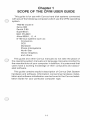
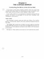
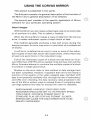
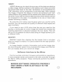
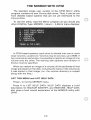
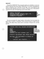
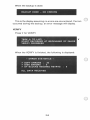
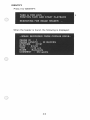
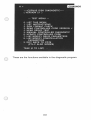
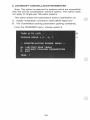
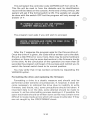
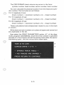
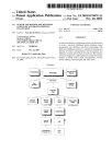
NOTICE
Corvus Systems, Inc. reserves the right to make improvements in the product
described in this manual at any time without notice.
DISCLAIMER OF ALL WARRANTIES AND LIABILITY
Corvus Systems, Inc. makes no warranties , either express or implied , with
respect to this manual or with respect to the software described in this manual,
its quality, performance, merchantability, or fitness for any particular purpose.
Corvus Systems, Inc. software is sold or licensed "as is. " In no event will Corvus
Systems, Inc. be liable for direct, indirect, incidental , or consequential damages
resulting from any defect in the software , even if Corvus Systems, Inc. has been
advised of the possibility of such damages. Regarding software supplied by
Apple Computer, Apple Computer Inc. makes no warranties , either expressed
or implied, regarding its merchantability or its fitness for any particular purpose.
Some states do not allow the exclusion or limitation of implied warranties or
liability for incidental or consequential damages, so the above limitation or
exclusion may not apply to you .
This manual is copyrighted and contains proprietary information. All rights are
reserved . This document may not, in whole or part , be copied, photocopied ,
reproduced , translated or reduced to any electronic medium or machine
readable form without prior consent, in writing , from Corvus Systems, Inc.
Revised manuals and update sheets will be published as needed and may be
purchased by writing to Corvus Systems, Inc.
Corvus Systems Information and Publication Department
©
1981 by Corvus Systems, Inc.
2029 OToole Avenue
San Jose, California 95131-1375
(408) 946-7700
TWX 910-338-0226
All rights reserved.
The following are registered trademarks of Corvus Systems: CONSTELLATION,
MIRROR, MULTIPLEXER and OMNINET. APPLE III is a trademark of Apple
Computer, Inc.
THE CP/M USER GUIDE
TABLE OF CONTENTS
1. Scope of the Manual .................................
2. The Corvus Mirror ....................................
Connecting the Mirror ................................
Using the Mirror ......................................
The Mirror with CP/M ........... . .....................
3. Diagnostics, Troubleshooting, & Updating ..............
The Diagnostic Program: CDIAGNOS ..................
Troubleshooting Guide .......................... .. ....
Firmware Update or Replacement .....................
4. Where do you go from here? ..........................
ii
00
00
00
00
00
00
00
00
00
00
Chapter 1
SCOPE OF THE CP/M USER GUIDE
This guide is for use with Corvus hard disk systems connected
with any of the following computers which use the CP/M operating
system.
TRS-80 model II
Xerox 820
Zenith Z-89
SuperBrain
NEC PC-8001
Altos 8000-1, -2, -4
S-100 bus systems such as:
Cromemco
CCS
Dynabyte
Ithaca Intersystems
North Star
Vector Graphics
and others
This guide and other Corvus manuals do not take the place of
the operating system manuals and language manuals provided by
the manufacturer of your computer. In addition, it is presumed that
users have a working knowledge of their computers and associated software.
This guide contains explicit description of Corvus Disk System
hardware and software. Information concerning hardware installation and software initialization can be found in the Corvus Installation Guide for your particular computer type.
1-1
Chapter 2
THE CORVUS MIRROR
Connecting the Mirror to the Corvus Disk
If you have a drive that contains a Mirror, then you need only
connect the video cable. For directions on how to connect your
video cable, see the section below labeled 'Video Cable.'
If you order a Mirror to complement an already existing Corvus
system, the Mirror is packaged in its own box complete with
installation instructions.
Video Cable
You received a phono plug set with your Mirror. For built-in
Mirrors, connect this cable to the drive cabinet backpanel and to
the VCR.
The VIDEO OUT connector on Mirror or drive cabinet connects
to the VIDEO IN connector on the VCR. The VIDEO IN connector on
the Mirror or drive cabinet connects to the VIDEO OUT connector
on the VCR.
See figure: Video cables connected to drive cabinet back panel.
2-1
USING THE CORVUS MIRROR
This section is presented in two parts:
The first part consists of a general description of the function of
the Mirror and a general description of its software.
The second part consists of the specific application of Mirror
software for your particular operating system.
About images
With the Mirror you can make a video tape copy of an entire disk
or of portions of a disk. This is called a 'backup.'
When the Corvus Mirror makes a copy of data from the Corvus
drive, it makes redundant copies of each block of data.
This method generally produces a few soft errors during the
backup process. An error may occur in one block of a multiple set
of blocks.
A soft error is defined as an error in one or more of the redundant copies of each disk sector (512 byte block), where there was
at least one good block in the redundant copy.
If all of the redundant copies of a block are bad (have an incorrect CRC) then a RETRY will be needed. Only during a retry will the
Mirror firmware attempt to combine the multiple copies of a block
to produce a single good block.
Studies on the error rates of this method of data storage have
not been completed. However, it appears that errors are mainly a
function of the quality of the video cassette tape. Certified VCR
tape is not presently available. But, through the use of redundancy
and CRC error checking, the data recovery rates projected in the
use of the Mirror system meet or exceed those of competing tape
cartridge systems and they far exceed the rates for diskettes.
WHEN MAKING A BACKUp, YOUR VIDEO TAPE
RECORDER SHOULD BE SET TO ITS FASTEST SPEED.
THIS IS BETA I FOR BETA FORMAT AND IT IS
STANDARD PLAY (SP) FOR VHS FORMAT. SLOWER
SPEEDS MAY CAUSE THE DATA ERROR RATE TO BE
GREATLY INCREASED.
2-2
Mirror Utility Options
QUIT
QUIT exits the Mirror utility.
BACKUP
BACKUP creates a Mirror image of an entire drive or a portion of
the volumes on a Corvus drive.
The tape file produced has a 'header block' that is used to save
information about the image being made. This information includes date, time, image size, and system type. There is also an
optional user comment line.
RESTORE
RESTORE reads an image from the tape and places it on the disk
in a volume of equivalent size. If the video image is of the entire
disk, the entire disk must be restored.
As each block is read from the tape, it is checked for recording
errors with a CRC check. If the CRC is bad, a soft error is counted
and the second image of the block is read. If this also fails, the third
and fourth images are tried. If all four fail, a retry error is counted.
Error correction for blocks that can not be recovered through
simple redundancy is done on a secondary pass (retry) of the
image. The Mirror utility program displays an error status following-a restore. If unrecovered blocks remain after the first pass, the
program will request that you rewind the tape to the starting
position for a second pass.
During a retry pass an error recovery scheme rebuilds blocks
that fail the CRC check in the initial restore. Corvus controller
firmware reads the multiple copies of the blocks and finds the
error locations. It pieces together a good block from the redundant copies by using the CRC check to determine the accuracy of
the recovered data.
This recovery method tolerates many more classes of errors
than systems which are limited to short burst error correction.
However, because of its complexity, a second pass consumes a
great deal of processing time in relation to the operations being
performed during the first pass of a restore.
2-3
VERIFY
VERIFY allows you to check the accuracy of the data recorded as
a video image. Verify is similar to the restore, but it does not write
the stored data back to the disk. Verification is accomplished by
CRC checking, not by comparison to the disk data. After reading
the image, it reports the status of errors encountered and indicates whether retry passes will be needed when data is restored to
the drive. If you wish to ensure data accuracy when blocks cannot
be recovered in one pass, it is possible to do one or more retry
passes following a restore.
By using the error status reports given when you use the verify
function, you can evaluate the quality of different video tapes and
tape recorders.
If you need to use a VCR other than the one you used for the
backup, a verify pass of a short image will reveal how closely the
tracking alignment is adjusted between the two decks. This will
tell you if it is possible to restore data using an image backed up on
a different VCR.
IDENTIFY
IDENTIFY reads then displays the file header that is included
when an image is created. It is used to determine the tape position
of timage.
An image header contains information such as the image size,
the host computer system that produced the image, and information you supply when you record an image.
Software Interface to the Mirror
The Corvus disk controller firmware controls Mirror operations.
A host computer sends commands to the disk controller through
the Mirror utility program . These commands perform the Mirror
operations.
MIRROR SOFTWARE OPERATES PROPERLY
ONLY WHEN A TAPE IS ACTUALLY IN THE
RECORDER.
2-4
Summary of Commands:
An image header (which includes the source and length information as well as the level of redundancy) is stored at the beginning of the stored data. Each image can be assigned a number
from 1 to 255, while 0 is reserved for directory usage.
Image headers can be read by using the IDENTIFY command. A
check for the proper file ID can be made or the next file header
encountered can be read.
The following is a list of the commands used by the Mirror:
BACKUp, IDENTIFY, RESTORE, RESTORE RETRY, VERIFY,
VERIFY RETRY, and REPORT ERRORS
Error Explanation:
Three of the most common errors that you may encounter during the use of the Mirror deal with tape timeout.
If you do not correctly position the cassette when you start the
tape, the IMAGE NOT FOUND error displays. The control program
searches for the start of an image for about one minute. If no
image is found within that time, it gives up the search.
If a restore is being done and the size of the image on the tape
does not match the size of the area being restored, the IMAGE
SIZE MISMATCH displays. The IDENTIFY option can be used to
determine the size (in blocks) of the video image.
Another error indicates that the tape you are trying to read has
been partially erased. This can occur if you are recording more
than one image on a video cassette and you fail to properly position the tape prior to recording. This error is called tape timeout
during playback operation.
2-5
THE MIRROR WITH CP/M
The standard single user version of the CP/M Mirror utility
program contains its own Corvus disk driver. Thus, it can be run
from diskette based systems that are not yet interfaced to the
Corvus drive.
To use the utility, load the Mirror program as you would any
other.COM file. Type: MIRROR <return>. A Mirror menu displays:
In CP/M based systems, each drive is divided into one or more
large volumes, usually two. Volumes may be any size, up to 8MB. If
two volumes are same size, it is possible to restore an image of one
volume onto the other. The starting disk address and number of
blocks must be specified.
When you restore an image of a volume, all the attributes of that
image are placed on the disk, including the name of the volume as
it was stored in that image. (I.e., the volume directory is copied
along with the files.)
LIST THIS MENU and LIST HELP DATA
Press L to list the MIRROR menu.
Press H to LIST HELP DATA. HELP DATA displays a brief
description for BACKUp, IDENTIFY, and RESTORE. HELP DATA
also gives a brief overall explanation of the MIRROR utility with
CP/M.
2-6
BACKUP
Press B for BACKUP. The computer asks you whether or not you
want to backup the entire disk. Press N for 'no' which indicates you
want to backup only a portion of the disk. You must specify the
starting disk address and the number of blocks your information
covers if you are not backing up an entire disk.
B
N
18000
20
You are prompted for tape header information that includes the
date, time, a name, a comment, and normal format or fast format.
Type in the date, time, name and a comment. Press N for normal
format.
2-7
When the backup is done:
BACKUP DONE -- NO ERRORS
This is the display assuming no errors are encountered. If errors
occurred during the backup, an error message will display.
VERIFY
Press V for VERIFY.
TASK (L TO LIST) :
START RECORDER AT BEGINNING OF IMAGE
VERIFY PROGRESS
When the VERIFY is finished, the following is displayed:
-- ERROR STATISTICS -# SOFT ERRORS : 30
# DISK ERRORS : 0
# OF BLOCKS NEEDING RETRYS
ALL DATA RECEIVED
2-8
o
V
IDENTIFY
Press I for IDENTIFY:
When the header is found, the following is displayed:
--IMAGE RECORDED FROM CORVUS DRIVE-IMAGE 10 : 1
IMAGE LENGTH : 20 BLOCKS
SYSTEMS : CP/M
DATE : 6/3/83
TIME : 11 :46 a.m.
NAME : Redwoods
COMMENT : Old giants
2-9
RESTORE
Press R for restore. The computer asks you if you want to restore
the entire disk. Whether or not you are restoring the entire disk,
you must specify the starting disk address and the number of
blocks your information covers.
TASK (L FOR LIST) :
RESTORE ENTIRE DISK (YIN) ?
STARTING DISK BLOCK # ?
NUMBER OF BLOCKS ?
CORVUS DRIVE # (1-4) ?
POSITION TAPE AND START PLAYBACK
RESTORE IN PROGRESS ...
When the restore is complete, the following is displayed:
--ERROR STATISTlCS-# SOFT ERRORS
:
3
# DISK ERRORS : 0
# OF BLOCKS NEEDING RETRYS
2-10
o
R
N
18000
20
1
Chapter 3
DIAGNOSTICS, TROUBLESHOOTING, &
UPDATING
The Diagnostic Program .................. .... ........... .
Troubleshooting Guide .. . ... . .. ................... .. ...... 8
Firmware update or replacement .................... .. . .. 10
Checking the firmware version ......................... 10
Updating the firmware ......... ..... . . ................. 11
Formatting the drive ................................... 12
Sparing tracks ........................................ 14
The interleave spec. . ................ . . . .. . ... . .. .. .... 19
The virtual drive offsets .. .... . . ...... .... ... .......... 19
Checking the virtual drive tab .... .. .................... 20
Updating the virtual drive tab ........................... 21
3-1
Chapter 3
DIAGNOSTICS, TROUBLESHOOTING,
UPDATING
THE DIAGNOSTIC PROGRAM
This is the CP/M version of the Corvus Disk Diagnostic
(CDIAGNOS.COM). This diagnostic program provides some relatively safe disk tests along with the ability to list and/or change
some parameters within the controller code.
Please read the whole section on diagnostics before attempting
to run CDIAGNOS.COM.
To avoid accidental change of parameters, the program should
be saved in a special location in order to minimize the likelihood of
it being run by unauthorized personnel.
The diagnostic program CDIAGNOS.COM must be run from the
floppy diskette drive, not from the Corvus hard disk.
To run the diagnostic program , type: CDIAGNOS< return >
3-2
A>
NOS
-----CORVUS DISK DIAGNOSTIC----( VERSION 2.1 )
--- TEST MENU --LIST THIS MENU
LIST INSTRUCTIONS
DISK FORMAT CHECK
READ CONTROLLER CODE VERSION #
HEAD SERVO TEST
MANUAL CONTROLLER DIAGNOSTIC
UPDATE CONTROLLER CODE
LIST/MODIFY DRIVE PARAMETERS
LIST/MODIFY CONSTELLATION
PARAMETERS
9. EXIT BACK TO CP/M
(CTL-C ALSO WORKS)
O.
1.
2.
3.
4.
5.
6.
7.
8.
TASK (0 TO LIST)
:
These are the functions available in the diagnostic program.
3-3
2. DISK FORMAT CHECK
Media defects may occur on the surface of the disk. A media
defect is defined as a read error that occurs more than ten times at
anyone track location. If not attended to, these physical defects
might show up as error signals from your computer when running
a valid program. Or perhaps a valid program just will not function
correctly.
The cyclical redundancy check (CRC) function checks for bad
sectors on the disk and reports the number and location of each of
them. Track reassignment is used to handle the defect areas.
The controller tries to read each 512 byte sector to verify that it
is 'good' (has a correct CRG). If it gets a bad CRC after twenty read
attempts, it will rewrite the sector to reset the CRC. This usually
takes 1 to 2 minutes.
3. READ CONTROLLER CODE VERSION #
This option displays the version number of the Corvus 2-80
firmware residing on the hard disk drive.
4. HEAD SERVO TEST
This test alternately reads 128 byte sectors at disk address 0 and
at the high disk address. This causes the heads to move back and
forth across the platter surfaces of the disk to check if the servo
mechanism is working properly. This test is mainly useful to verify
that the drive will actually read data and move its heads.
5. MANUAL CONTROLLER DIAGNOSTIC
This option should not be used unless under direct supervision
of Corvus customer service personnel.
6. UPDATE CONTROLLER CODE
This option allows the update or initial installation of controller
code on the Corvus drive. This code resides on protected tracks of
the hard disk. Normally this code cannot be written to or read by
the user (even accidentally). However it can be made accessible
(to writing) by turning on the format switch. This option replaces
the separate program CCODE.COM that had similar capabilities.
3-4
To use this option:
A. Power the drive down. If your drive has a format switch (under
the front bezel of the drive), turn it on and proceed to step C.
The format switch is the second switch from the right under
the bezel.)
B. Power the drive back up.
C. Run this program from your floppy based CP/M and select the
update option.
D. After the code is written out, turn off the format switch and
reset the drive by either using the reset switch or by powering
the drive down and up again.
Note: There is a hidden option within this option that allows the
drive to be reformatted and the controller code replaced. This
should only be done as a last resort and under the direct supervision of Corvus Customer Service personnel. This is because the
format operation destroys data in the firmware area as well as in
the user area.
7. LIST/MODIFY DRIVE PARAMETERS
This option allows the examination and/or change of the following:
7 A. SPARED TRACK TABLE
This table specifies physical track numbers which are to be
skipped over when the controller accesses data on the drive. This
allows the hiding of the existence of media defects from the
external user. (The data surface will look perfect to him.)
7B. SECTOR INTERLEAVING SPEC.
The defaults used here have been optimized for small computers like the TRS 80 Model II. Typically, we have selected a value
of:
9 for the 10 and 20 megabyte drives
12 for the 5 megabyte drive
7C. VIRTUAL DRIVE TRACK OFFSET TABLE
This table allows one drive to behave as if it were several smaller
drives daisy-chained together. The table entries specify the track
number where these virtual drives start.
Normally, there would be no occasion to disturb these
parameters unless the drive has been reformatted or a bad track
develops.
3-5
8. LIST/MODIFY CONSTELLATION PARAMETERS
Note: This option is reserved for systems which are compatible
with the Corvus Constellation network system. The option does
not apply to single-user flat-cable systems.
This option allows the examination and/or modification of:
A. master multiplexer connection table (MUX table) and
B. The Constellation polling parameters (polling constants).
From the CDIAGNOS menu, choose option 8.
TASK (0 TO LIST)
:
8
CORVUS DRIVE # (1 - 4)
?
--- CONSTELLATION PARAM . MENU --M: LIST/EDIT MUX TABLE
P: LIST/EDIT POLLING PARAMETERS
E: EXIT
TASK
?
3-6
1
To examine or modify the MUX table, enter M.
M
N
The MUX table is used to specify what is connected to the
master multiplexer. It is usually set to assume that all the slots have
MUX on them. This allows it to work correctly on systems that are
only using a host multiplexer.
To examine or modify the polling parameters, choose the P
·option:
TASK
p
?
--- POLLING PARAMETERS --180
16
32
o
DO YOU WISH TO CHANGE THE POLLING
PARAMETERS (NOT RECOMMENDED) (YIN) ?
These numbers determine certain aspects of the Constellation
polling environment. The default values (listed above) are correct
for most systems.
On systems with interrupts that could interrupt disk activity
(such as a real time clock or screen refresh) the second value
should be set to a larger number like 32. This is the recommended
value if Intertec SuperBrain is connected to the multiplexer.
3-7
TROUBLESHOOTING GUIDE
If your disk system is not performing normally, review these
points:
1. Be sure the drive fuse is the proper value. Place all switches
under the lights on the front panel to the left position. Then
connect the ac cord, provided with the drive, to your drive and
to a wall socket.
2. Power on the drive and wait for it to come ready (as long as 40
seconds). When all the lights on the front panel go off and the
ready light stays on, the drive is ready and all should be well. Go
to the following section titled "Checking the firmware version."
3. If the Corvus disk system fails to come ready, try the following
procedures:
• Insure all cables are properly connected and switches are in
the correct position for the operating configuration.
• Reset the drive manually using the reset switch on the front
panel. If the drive now comes ready, the electro mechanical
head lock may have been stuck. Otherwise:
• Power down the disk system and initiate the power up sequence again.
4. If your drive still does not come ready, power down.
Power down your drive and switch the format switch to the
right. This is the third switch to the right, under the indicator
lights. Repeat the power up sequence. If your drive now comes
ready, you need to put new firmware on your disk.
First go to the following section titled "Firmware update or
replacement" and try to update your firmware. If the update
takes, then your drive should be all right.
If the update is interrupted by a R/Werror message, you need to
format the drive according to the sUbsection titled: "Replacing
the firmware."
5. You may also need to spare tracks or update the virtual drive
table. If so, see the appropriate following sections.
6. If none of the previous suggestions work, contact the nearest
Corvus Systems Service Center for assistance.
3-8
FIRMWARE UPDATE OR REPLACEMENT
You should follow the procedures described in the following
sections in order to check your firmware version, to update your
firmware version, to format your drive, or to verify and change the
Virtual Drive / Track Offset Table. These procedures require that
you have the latest version of the Corvus utilities diskette and a
floppy drive connected to your computer.
Checking Firmware Version
Checking the firmware version is done by using the diagnostic
program that is found on the Corvus utilities diskette.
Execute the Corvus diagnostic program (CDIAGNOS.COM) and
select menu option #3. It will then prompt you for the Corvus drive
# (usually 1). After entering the appropriate drive #, the controller
firmware version will be listed.
TASK (0 TO LIST)
3
:
CORVUS DRIVE # (1-4)
1
?
V16 .3 CORVUS SYSTEMS 27-AUG-81
REVISION# 31
CONTROLLER ROM VERSION #
TASK (0 TO LIST)
:
56
0
Updating the Firmware
Run the diagnostic program. Select the UPDATE option (#6).
The program will prompt you for the controller code file name:
CONTROLLER CODE FILE NAME (CORVXX.CLR):
Here specify the controller code file name and optionally the
disk drive on which it is to be found. For instance:
CONTROLLER CODE FILE NAME (CORVXX.CLR):
B.CORVB5.CLR
3-9
This will select the controller code CORVB5.CLR from drive B: .
This file will be read in from the diskette and its identification
record will be listed on the console. At the end of this printout, the
system will ask if the format switch is ON. The update can usually
be done with the switch OFF but the program will only accept an
answer of Y.
IS FORMAT SWITCH ON (OR FORMAT
JUMPER INSTALLED) (YIN) ?
y
The program next asks if you still wish to proceed.
WRITE CONTROLLER CODE TO DISK (YIN)
CORVUS DRIVE # (1 - 4) ?
?
y
1
After the Y response the program asks for the Corvus drive # .
Once the drive # is given, the code will be written out to the disk.
Should a disk R/W error occur here, there may be some hardware
problem or there may be some bad sectors in the firmware tracks
of the drive. At the conclusion of the operation (no more than 20
seconds) the program will boast of its success and remind you to
switch the format switch back to its normal position.
You may verify that it has worked correctly by requesting the
VERSION option.
Formatting the drive and replacing the firmware
Formatting a drive is a drastic measure and should only be
performed under extreme circumstances. If, however, it does become necessary to reformat the drive (due to inability to write
firmware, bad tracks, etc.) some precautions should be taken. If
important data is on the disk, some attempt should be made to
recover it, as the reformatting process destroys it. If possible, the
spare track table should be written down as this may contain some
difficult to locate media errors which will cause trouble later if they
are not caught by the CRC/FORMAT check.
3-10
The process of formatting is quite simple and is accomplished
through the diagnostic program. First, turn the format switch on
and power up the drive.
FOR 10 AND 20 MEGABYTE DRIVES, YOU MUST MAKE
SURE THE HEAD RE-ZEROES AND THE DRIVE IS READY.
ON 5 MEGABYTE DRIVES THE HEADS MAY NOT RE-ZERO
UNTIL YOU BEGIN FORMATTING.
The FORMAT option is a hidden suboption of the CP/M diagnostic program (CDIAGNOS.COM) and should be performed only
under the direct supervision of Corvus Customer Service personnel. To format the drive, run CDIAGNOS from your diskette based
system and select the UPDATE option. Follow the procedures
previously described, but specify the controller firmware file
name with the extension .FMT instead of .CLR .
The program will prompt you for the Corvus drive # (usually 1)
and warn you that it is about ready to format the drive. The format
operation will take 1 - 2 minutes depending on the drive size (5 MB
drives are slower). If you get a R/W error, try repeating the operation. If this fails, you may have a hardware problem.
When it has finished, the program asks you to power down the
drive, turn off the format switch, and power up the drive. The drive
should re-zero and come ready. (Allow 30 to 90 seconds.) If it does,
you have successfully formatted the drive. If the process fails at
any point, you should start again, checking all connections carefully before proceding.
If you have successfully formatted the drive, the next step is to
write the spare track table. If you salvaged the original spare track
table, just write the new tracks using the DRIVE PARAMETERS
option of the diagnostic program. If you could not retrieve the
table, you must use the CRC/FORMATcheck to find any errors and
spare them out. In either case, you should run at least one pass of
the CRC/FORMAT check to ensure there are no other errors. See
the next section for more information.
3-11
Sparing Tracks
The REV B Corvus drives contain a total of seven extra tracks for
the user area. These tracks can be used in place of tracks in the
user area if a user track is found to be defective.
Defective tracks are 'spared out' by making the disk controller
simply skip over them (rather than re-direct requests to a separate
spare track pool). This choice of sparing methods was chosen to
allow our mirror backup system to function more simply. One
undesirable consequence of this choice of methods is that all the
data on the disk beyond the newly 'spared track' will now be offset
one track from its previous position. Thus this data must be
backed up on some external storage unit before the track is
spared . The data can then be restored after the new spare track
table is made.
Corvus provides a diagnostic program to users which makes the
process very simple.
BACKUP YOUR DRIVE BEFORE SPARING TRACKS
OUT. FAILURE TO DO SO WILL RESULT IN THE LOSS
OF ALL DATA BEYOND THE SPARED TRACK. YOU
WILL HAVE TO RESTORE FROM A MIRROR BACKUP
OR RE-INITIALIZE YOUR SYSTEM.
There are several possible ways of discovering bad tracks. You
may getI/O errors during normal operation. The bad spots may
show up in a CRC/FORMAT check.
If the drive returns I/O errors in the same spot consistently, you
probably have a bad track. Calculating the physical location of the
bad track from the information available to you is nearly
impossible. The best thing to do is run the diagnostic program and
select the CRC/FORMATcheck from the menu. In almost all cases,
the error will show up in this diagnostic routine.
3-12
The CRC/FORMAT check returns any errors in the form:
cylinder number, head number, sector number, track number
You can calculate the physical location from the head and cylinder number. The formulas are as follows:
For 5 megabyte drives:
(track number)
=
«cylinder number) x 4)
+ (head number)
For 10 megabyte drives:
(track number)
=
«cylinder number) x 3)
+ (head number)
For 20 megabyte drives:
(track number)
=
«cylinder number) x 5)
+ (head number)
These calculations have already been made for you in the track
# column.
Write down se track numbers on a piece of paper and cancel out
any duplicates in the list.
Now select the DRIVE PARAMETERS option, #7, of the diagnostic program (CDIAGNOS). Once the drive number is specified
(usually #1), the program will list the spared track table, the sector
interleaving spec., and the virtual drive offset table.
TASK (0 TO LIST)
:
CORVUS DRIVE # (1-4)
7
?
--- SPARED TRACK TABLE ---
> NO TRACKS ARE SPARED <
PRESS RETURN TO CONTINUE
3-13
1
If there are any spared tracks, you should write the list on a piece
of paper (to attach to the drive) or in a notebook. If you ever have to
reformat your drive, you will want to spare out these tracks again.
Then <return>:
SECTOR INTERLEAVING SPEC.
12
PRESS RETURN TO CONTINUE
--- VIRTUAL DRIVE TRACK --OFFSET TABLE
DRIVE
TRACK
1
o
--------- WARN ING
CHANGING ANY OF FOLLOWING PARAMETERS
CAN MAKE ANY USER DATA STORED ON THE
DISK UNUSABLE
DO YOU WISH TO CONTINUE
?
,y
After a Y, the drive parameters menu is displayed which gives
options for various changes.
------ DRIVE PARAMETERS MENU -----S: SPARED TRACK TABLE
I: SECTOR INTERLEAVING
V: VIRTUAL DRIVE OFFSET TABLE
E: EXIT
TASK
s
?
Compare your CRC error list against the spared track list. Cross
off any tracks in your CRC error list that appear in the spared track
list. Any remaining on your CRC error list must be spared out.
3-14
These tracks are simply added to the spared track table with the
ADD option. The table is sorted automatically after each addition.
Spared track numbers are displayed (and later stored) in ascending order.
TASK
S
?
--- SPARED TRACK TABLE --> NO TRACKS ARE SPARED <
ADD, REMOVE. OR ·EXIT (A.R.E)
NEW TRACK # TO SPARE
?
A
17
?
--- SPARED TRACK TABLE --17
ADD. REMOVE. OR EXIT (A.R.E)
TRACK # TO REMOVE
?
R
17
?
--- SPARED TRACK TABLE --> NO TRACKS ARE SPARED <
ADD, REMOVE. OR EXIT (A.R,E)
?
E
The computer displays the current spare track list and the
prompt menu. To add a track to the list, select A for ADD. The
program prompts you for the track number. If you enter the wrong
track number, you can select R for REMOVE to remove it. Then
select A again to enter the correct one. When you have finished
editing the spare track list, press E for EXIT.
Exit will redisplay the drive parameters menu. If yo~ are through
making your changes, select option E for exit. If no changes were
made, the main menu will be re-displayed. If changes were made,
you will be asked if you want these changes written back to the
disk. Enter Y to update the DRIVE PARAMETERS.
The Interleave Spec.
The interleave spec. should always be left at its default value.
3-15
The Virtual Drive Offsets
TASK
v
?
ALL CP/M BASED SYSTEMS CAN ADDRESS
THE DRIVE AS ONE UNIT. THUS THE
VDO TABLE SHOULD BE SET WITH AN
OFFSET OF 0 FOR THE VIRTUAL DRIVE 1
--- VIRTUAL DRIVE/TRACK --OFFSET TABLE
DRIVE
TRACK
1
VIRTUAL DRIVE 1
VIRTUAL DRIVE 2
o
: 0
:-
Checking the virtual drive/track offset table (20 MB drives only)
You should still be in the diagnostic program. Select the DRIVE
PARAMETERS option.
J
After entering the drive #, you will set a display of the drive
parameters. The virtual offset table is the last table displayed. For
a 20 MB drive, this usually has the form:
This number (or numbers) allows the user to make the drive
appear to be subdivided into a number (less than 8) of subdrives
that appear to the software as daisy chained drives. (This scheme
is mainly used on Corvus' Apple products.) In the example above,
we could still address the whole drive as Corvus drive #1, but the
controller would also respond as Corvus drive #2 and address the
last half of the disk space.
3-16
Note: If your system does use these offsets for drive 2 - 8 then be
sure to record the values used and restore these values whenever
the drive is reformatted. If you use the wrong values later on, the
data stored on the drive wiJ/ be addressed wrong and thus be
unusable.
Updating the virtual drive table (for 20 MB drives only)
EXECUTING THIS OPTION WILL DESTROY DATA ON
THE DRIVE. DO NOT PROCEED UNLESS YOU HAVE
BACKED UP ALL DATA ON THE DRIVE.
You should stiff be running the diagnostic program. Select the
DRIVE PARAMETERS option, task V, as shown before.
Since you want to set up the drive for two drive emulation, you
enter 0 as the track offset for drive one, and 9xx (947, 976, or other)
for drive two. Enter a negative sign ( - ) for the track offset for
drive three (or the last drive). The negative says that this is the end
of the table.
BE SURE TO USE THE CORRECT NUMBER AS THE
TRACK OFFSET OF THE SECOND DRIVE. WHILE USE
OF ANOTHER NUMBER MAY WORK FOR A WHILE,
EVENTUALLY THINGS MAY START TO OVERWRITE
ONE ANOTHER. ESPECIALLY IF YOU ARE USING
PIPES.
To finish the update, you must answer Y to the questions about
writing changes back to disk, when you exit the drive parameters
section.
3-17
NOTES:
Chapter 4
WHERE DO YOU GO FROM HERE?
The current Xerox 820 and Zenith Z89/H89 Corvus compatible
product line consists of single user flat cable interface products
only.
Future enhancements will include Corvus Constellation and
Omninet Network compatibility. ·In addition, add-on disk systems
will be available which will allow up to 80 MB of mass storage
connected to a single disk or network system.
4-1