1
Agilent E5061A/E5062A ENA Series
ENA Series RF Network Analyzers
Programmer’s Guide
Fifth Edition
FIRMWARE REVISIONS
This manual applies directly to instruments that have the firmware revision A.03.00.
For additional information about firmware revisions, see Appendix A.
Manufacturing No. E5061-90042
October 2008
Notices
The information contained in this document is subject to change without notice.
This document contains proprietary information that is protected by copyright. All rights
are reserved. No part of this document may be photocopied, reproduced, or translated to
another language without the prior written consent of Agilent Technologies.
Microsoft®,MS-DOS®,Windows®,Visual C++®,Visual Basic®,VBA® and Excel® are
registered
UNIX is a registered trademark in U.S. and other countries, licensed
exclusively through X/Open Company Limited.
Portions ©Copyright 1996, Microsoft Corporation. All rights reserved.
© Copyright 2004, 2005, 2006, 2007 Agilent Technologies
Manual Printing History
The manual’s printing date and part number indicate its current edition. The printing date
changes when a new edition is printed. (Minor corrections and updates that are
incorporated at reprint do not cause the date to change.) The manual part number changes
when extensive technical changes are incorporated.
February 2004
First Edition (part number: E5061-90002)
September 2005
Second Edition (part number: E5061-90012, changes for firmware
version A.02.00)
June 2005
Third Edition (part number: E5061-90022, changes for firmware
version A.02.10)
February 2007
Fourth Edition (part number: E5061-90032, changes for firmware
version A.03.00)
October 2008
Fifth Edition (part number: E5061-90042)
2
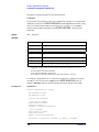
Typeface Conventions
Bold
Boldface type is used when a term is defined. For
example: icons are symbols.
Italic
Italic type is used for emphasis and for titles of
manuals and other publications.
[Key]
Indicates the hardkey whose key label is Key.
[Key] - Item
Indicates a series of key operations in which you
press the [Key] key, select (highlight) the item
called Item on the displayed menu using the [↓]
key and so on, and then press the [Enter] key.
Sample Program Disk
A sample program disk (Agilent part number: E5061-180x0) is furnished with this manual.
The disk contains the sample programs used in this manual.
The customer shall have the personal, non-transferable rights to use, copy, or modify
SAMPLE PROGRAMS in this manual for the customer’s internal operations. The
customer shall use the SAMPLE PROGRAMS solely and exclusively for their own
purposes and shall not license, lease, market, or distribute the SAMPLE PROGRAMS or
modification of any part thereof.
Agilent Technologies shall not be liable for the quality, performance, or behavior of the
SAMPLE PROGRAMS. Agilent Technologies especially disclaims any responsibility for
the operation of the SAMPLE PROGRAMS to be uninterrupted or error-free. The
SAMPLE PROGRAMS are provided AS IS.
AGILENT TECHNOLOGIES DISCLAIMS ANY IMPLIED WARRANTY OF
MERCHANTABILITY AND FITNESS FOR A PARTICULAR PURPOSE.
Agilent Technologies shall not be liable for any infringement of any patent, trademark,
copyright, or other proprietary right by the SAMPLE PROGRAMS or their use. Agilent
Technologies does not warrant that the SAMPLE PROGRAMS are free from
infringements of such rights of third parties. However, Agilent Technologies will not
knowingly infringe or deliver software that infringes the patent, trademark, copyright, or
other proprietary right of a third party.
3
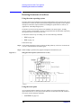
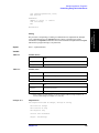
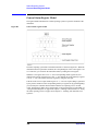
Documentation Map
The following manuals are available for the Agilent E5061A/E5062A.
•
User’s Guide (Part Number E5061-900x0, attached to Option ABA)
This manual describes most of the basic information needed to use the
E5061A/E5062A. It provides a function overview, detailed operation procedure for
each function (from preparation for measurement to analysis of measurement results),
measurement examples, specifications, and supplemental information. For
programming guidance on performing automatic measurement with the
E5061A/E5062A, please see the Programming Manual.
•
Installation and Quick Start Guide (Part Number E5061-900x1, attached to Option
ABA)
This manual describes installation of the instrument after it is delivered and the basic
procedures for applications and analysis. Refer to this manual when you use the
E5061A/E5062A for the first time.
•
Programmer’s Guide (Part Number E5061-900x2, attached to Option ABA)
This manual provides programming information for performing automatic
measurement with the E5061A/E5062A. It includes an outline of remote control,
procedures for detecting measurement start (trigger) and end (sweep end), application
programming examples, a command reference, and related information.
•
VBA Programmer’s Guide (Part Number E5061-900x3, attached to Option ABA)
This manual describes programming information for performing automatic
measurement with internal controller. It includes an outline of VBA programming,
some sample programming examples, a COM object reference, and related
information.
•
Option 100 Fault Location and Structural Return Loss Measurement User’s Guide
Supplement (Part Number E5061-900x4, attached to Option 100)
This manual describes information for using the fault location and structual return loss
measurement functions.
NOTE
The number position shown by “x” in the part numbers above indicates the edition number.
This convention is applied to each manual, CD-ROM (for manuals), and sample programs
disk issued.
4
Contents
1. Making Effective Use of This Manual
Contents of This Manual. . . . . . . . . . . . . . . . . . . . . . . . . . . . . . . . . . . . . . . . . . . . . . . . . . . . . . . . . . . . . . . . 18
How To Use This Manual . . . . . . . . . . . . . . . . . . . . . . . . . . . . . . . . . . . . . . . . . . . . . . . . . . . . . . . . . . . . . . . 20
Looking up SCPI commands. . . . . . . . . . . . . . . . . . . . . . . . . . . . . . . . . . . . . . . . . . . . . . . . . . . . . . . . . . . 20
Using sample programs. . . . . . . . . . . . . . . . . . . . . . . . . . . . . . . . . . . . . . . . . . . . . . . . . . . . . . . . . . . . . . . 21
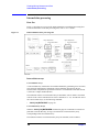
2. Overview of Remote Control
Types of remote control system . . . . . . . . . . . . . . . . . . . . . . . . . . . . . . . . . . . . . . . . . . . . . . . . . . . . . . . . . . 24
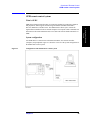
GPIB remote control system . . . . . . . . . . . . . . . . . . . . . . . . . . . . . . . . . . . . . . . . . . . . . . . . . . . . . . . . . . . . 25
What is GPIB? . . . . . . . . . . . . . . . . . . . . . . . . . . . . . . . . . . . . . . . . . . . . . . . . . . . . . . . . . . . . . . . . . . . . . 25
System configuration . . . . . . . . . . . . . . . . . . . . . . . . . . . . . . . . . . . . . . . . . . . . . . . . . . . . . . . . . . . . . . . . 25
Device selector . . . . . . . . . . . . . . . . . . . . . . . . . . . . . . . . . . . . . . . . . . . . . . . . . . . . . . . . . . . . . . . . . . . . . 26
LAN remote control system . . . . . . . . . . . . . . . . . . . . . . . . . . . . . . . . . . . . . . . . . . . . . . . . . . . . . . . . . . . . . 27
System configuration . . . . . . . . . . . . . . . . . . . . . . . . . . . . . . . . . . . . . . . . . . . . . . . . . . . . . . . . . . . . . . . . 27
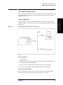
Control over SICL-LAN server. . . . . . . . . . . . . . . . . . . . . . . . . . . . . . . . . . . . . . . . . . . . . . . . . . . . . . . . . 28
Control over telnet server . . . . . . . . . . . . . . . . . . . . . . . . . . . . . . . . . . . . . . . . . . . . . . . . . . . . . . . . . . . . . 33
Sending SCPI command messages . . . . . . . . . . . . . . . . . . . . . . . . . . . . . . . . . . . . . . . . . . . . . . . . . . . . . . . 36
Types and structure of commands . . . . . . . . . . . . . . . . . . . . . . . . . . . . . . . . . . . . . . . . . . . . . . . . . . . . . . 36
Grammar of messages . . . . . . . . . . . . . . . . . . . . . . . . . . . . . . . . . . . . . . . . . . . . . . . . . . . . . . . . . . . . . . . 37
Remote mode . . . . . . . . . . . . . . . . . . . . . . . . . . . . . . . . . . . . . . . . . . . . . . . . . . . . . . . . . . . . . . . . . . . . . . 38
3. Setting Up the Analyzer
Selecting the Active Channel/Trace . . . . . . . . . . . . . . . . . . . . . . . . . . . . . . . . . . . . . . . . . . . . . . . . . . . . . . . 40
Configuring Measurement Conditions . . . . . . . . . . . . . . . . . . . . . . . . . . . . . . . . . . . . . . . . . . . . . . . . . . . . . 41
Setting the Number of Traces . . . . . . . . . . . . . . . . . . . . . . . . . . . . . . . . . . . . . . . . . . . . . . . . . . . . . . . . . . 41
Selecting Measurement Parameters . . . . . . . . . . . . . . . . . . . . . . . . . . . . . . . . . . . . . . . . . . . . . . . . . . . . . 41
Setting the Sweep Condition (Stimulus) . . . . . . . . . . . . . . . . . . . . . . . . . . . . . . . . . . . . . . . . . . . . . . . . . . 41
Configuring Averaging Settings . . . . . . . . . . . . . . . . . . . . . . . . . . . . . . . . . . . . . . . . . . . . . . . . . . . . . . . . 43
Setting the System Z0 . . . . . . . . . . . . . . . . . . . . . . . . . . . . . . . . . . . . . . . . . . . . . . . . . . . . . . . . . . . . . . . . 43
Configuring Display Settings . . . . . . . . . . . . . . . . . . . . . . . . . . . . . . . . . . . . . . . . . . . . . . . . . . . . . . . . . . . . 44
Setting the Layout of Windows and Graphs . . . . . . . . . . . . . . . . . . . . . . . . . . . . . . . . . . . . . . . . . . . . . . . 44
Configuring Trace Display Settings . . . . . . . . . . . . . . . . . . . . . . . . . . . . . . . . . . . . . . . . . . . . . . . . . . . . . 47
Printing a Message in the Echo Window . . . . . . . . . . . . . . . . . . . . . . . . . . . . . . . . . . . . . . . . . . . . . . . . . 49
Turning On or Off Display Update . . . . . . . . . . . . . . . . . . . . . . . . . . . . . . . . . . . . . . . . . . . . . . . . . . . . . . 49
Showing/Hiding Frequencies . . . . . . . . . . . . . . . . . . . . . . . . . . . . . . . . . . . . . . . . . . . . . . . . . . . . . . . . . . 49
Showing or Hiding the Title . . . . . . . . . . . . . . . . . . . . . . . . . . . . . . . . . . . . . . . . . . . . . . . . . . . . . . . . . . . 49
Configuring Date/Time Display . . . . . . . . . . . . . . . . . . . . . . . . . . . . . . . . . . . . . . . . . . . . . . . . . . . . . . . . 49
Turning On or Off the LCD Backlight . . . . . . . . . . . . . . . . . . . . . . . . . . . . . . . . . . . . . . . . . . . . . . . . . . . 49
Setting display colors . . . . . . . . . . . . . . . . . . . . . . . . . . . . . . . . . . . . . . . . . . . . . . . . . . . . . . . . . . . . . . . . 50
Saving and Loading the Settings . . . . . . . . . . . . . . . . . . . . . . . . . . . . . . . . . . . . . . . . . . . . . . . . . . . . . . . . . 51
Sample Program . . . . . . . . . . . . . . . . . . . . . . . . . . . . . . . . . . . . . . . . . . . . . . . . . . . . . . . . . . . . . . . . . . . . . . 52
4. Performing a Calibration
Calibration . . . . . . . . . . . . . . . . . . . . . . . . . . . . . . . . . . . . . . . . . . . . . . . . . . . . . . . . . . . . . . . . . . . . . . . . . . 60
Performing a Calibration (Obtaining the Calibration Coefficients) . . . . . . . . . . . . . . . . . . . . . . . . . . . . . 60
Defining Calibration Kits . . . . . . . . . . . . . . . . . . . . . . . . . . . . . . . . . . . . . . . . . . . . . . . . . . . . . . . . . . . . . 64
Saving and Loading Calibration Coefficients . . . . . . . . . . . . . . . . . . . . . . . . . . . . . . . . . . . . . . . . . . . . . . 66
Sample Program . . . . . . . . . . . . . . . . . . . . . . . . . . . . . . . . . . . . . . . . . . . . . . . . . . . . . . . . . . . . . . . . . . . . . . 67
5
Contents
Calibration . . . . . . . . . . . . . . . . . . . . . . . . . . . . . . . . . . . . . . . . . . . . . . . . . . . . . . . . . . . . . . . . . . . . . . . . 67
ECal . . . . . . . . . . . . . . . . . . . . . . . . . . . . . . . . . . . . . . . . . . . . . . . . . . . . . . . . . . . . . . . . . . . . . . . . . . . . . 75
5. Making a Measurement
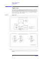
Trigger system . . . . . . . . . . . . . . . . . . . . . . . . . . . . . . . . . . . . . . . . . . . . . . . . . . . . . . . . . . . . . . . . . . . . . . .
System-wide state and transition . . . . . . . . . . . . . . . . . . . . . . . . . . . . . . . . . . . . . . . . . . . . . . . . . . . . . . .
Channel-wide state and transition. . . . . . . . . . . . . . . . . . . . . . . . . . . . . . . . . . . . . . . . . . . . . . . . . . . . . . .
Staring a Measurement Cycle (Triggering the instrument) . . . . . . . . . . . . . . . . . . . . . . . . . . . . . . . . . . . . .
Configuring the Instrument to Automatically Perform Continuous Measurement . . . . . . . . . . . . . . . . .
Starting Measurement on Demand . . . . . . . . . . . . . . . . . . . . . . . . . . . . . . . . . . . . . . . . . . . . . . . . . . . . . .
Waiting for the End of Measurement . . . . . . . . . . . . . . . . . . . . . . . . . . . . . . . . . . . . . . . . . . . . . . . . . . . . . .
Using the Status Register . . . . . . . . . . . . . . . . . . . . . . . . . . . . . . . . . . . . . . . . . . . . . . . . . . . . . . . . . . . . .
Using the :TRIG:SING Command. . . . . . . . . . . . . . . . . . . . . . . . . . . . . . . . . . . . . . . . . . . . . . . . . . . . . .
Using Wait Time . . . . . . . . . . . . . . . . . . . . . . . . . . . . . . . . . . . . . . . . . . . . . . . . . . . . . . . . . . . . . . . . . . . .
80
81
82
83
83
83
84
84
87
88
6. Analyzing Data
Retrieving Measurement Results at Specified Points. . . . . . . . . . . . . . . . . . . . . . . . . . . . . . . . . . . . . . . . . . 90
Showing/Hiding Markers . . . . . . . . . . . . . . . . . . . . . . . . . . . . . . . . . . . . . . . . . . . . . . . . . . . . . . . . . . . . . 90
Turning On or Off Reference Marker Mode. . . . . . . . . . . . . . . . . . . . . . . . . . . . . . . . . . . . . . . . . . . . . . . 90
Setting (Changing) and Retrieving Stimulus Value at Marker Positions . . . . . . . . . . . . . . . . . . . . . . . . . 90
Retrieving Measurement Results at Marker Positions . . . . . . . . . . . . . . . . . . . . . . . . . . . . . . . . . . . . . . . 90
Searching for Positions That Match Specified Criteria . . . . . . . . . . . . . . . . . . . . . . . . . . . . . . . . . . . . . . . . 91
Using Marker Search . . . . . . . . . . . . . . . . . . . . . . . . . . . . . . . . . . . . . . . . . . . . . . . . . . . . . . . . . . . . . . . . 91
Using the Analysis Command . . . . . . . . . . . . . . . . . . . . . . . . . . . . . . . . . . . . . . . . . . . . . . . . . . . . . . . . . 93
Sample Program . . . . . . . . . . . . . . . . . . . . . . . . . . . . . . . . . . . . . . . . . . . . . . . . . . . . . . . . . . . . . . . . . . . . 95
Bandwidth Search. . . . . . . . . . . . . . . . . . . . . . . . . . . . . . . . . . . . . . . . . . . . . . . . . . . . . . . . . . . . . . . . . . . . . 97
Setting the Bandwidth Definition Value . . . . . . . . . . . . . . . . . . . . . . . . . . . . . . . . . . . . . . . . . . . . . . . . . . 97
Retrieving Bandwidth Search Results . . . . . . . . . . . . . . . . . . . . . . . . . . . . . . . . . . . . . . . . . . . . . . . . . . . 97
Sample Program . . . . . . . . . . . . . . . . . . . . . . . . . . . . . . . . . . . . . . . . . . . . . . . . . . . . . . . . . . . . . . . . . . . . 97
Notch search . . . . . . . . . . . . . . . . . . . . . . . . . . . . . . . . . . . . . . . . . . . . . . . . . . . . . . . . . . . . . . . . . . . . . . . . . 99
Setting the notch definition value . . . . . . . . . . . . . . . . . . . . . . . . . . . . . . . . . . . . . . . . . . . . . . . . . . . . . . . 99
Reading out the notch search result . . . . . . . . . . . . . . . . . . . . . . . . . . . . . . . . . . . . . . . . . . . . . . . . . . . . . 99
Statistical Analysis . . . . . . . . . . . . . . . . . . . . . . . . . . . . . . . . . . . . . . . . . . . . . . . . . . . . . . . . . . . . . . . . . . . 100
Analyzing impedance . . . . . . . . . . . . . . . . . . . . . . . . . . . . . . . . . . . . . . . . . . . . . . . . . . . . . . . . . . . . . . . . . 101
7. Reading/Writing Measurement Data
Data Transfer Format . . . . . . . . . . . . . . . . . . . . . . . . . . . . . . . . . . . . . . . . . . . . . . . . . . . . . . . . . . . . . . . . .
ASCII Transfer Format . . . . . . . . . . . . . . . . . . . . . . . . . . . . . . . . . . . . . . . . . . . . . . . . . . . . . . . . . . . . . .
Binary Transfer Format. . . . . . . . . . . . . . . . . . . . . . . . . . . . . . . . . . . . . . . . . . . . . . . . . . . . . . . . . . . . . .
Internal data processing . . . . . . . . . . . . . . . . . . . . . . . . . . . . . . . . . . . . . . . . . . . . . . . . . . . . . . . . . . . . . . .
Data flow. . . . . . . . . . . . . . . . . . . . . . . . . . . . . . . . . . . . . . . . . . . . . . . . . . . . . . . . . . . . . . . . . . . . . . . . .
Internal data arrays . . . . . . . . . . . . . . . . . . . . . . . . . . . . . . . . . . . . . . . . . . . . . . . . . . . . . . . . . . . . . . . . .
Retrieving Measurement Results . . . . . . . . . . . . . . . . . . . . . . . . . . . . . . . . . . . . . . . . . . . . . . . . . . . . . . . .
Retrieving Internal Data Arrays . . . . . . . . . . . . . . . . . . . . . . . . . . . . . . . . . . . . . . . . . . . . . . . . . . . . . . .
Entering Data into a Trace . . . . . . . . . . . . . . . . . . . . . . . . . . . . . . . . . . . . . . . . . . . . . . . . . . . . . . . . . . . . .
104
105
106
108
108
108
111
111
115
8. Limit Test
Performing a Limit Test . . . . . . . . . . . . . . . . . . . . . . . . . . . . . . . . . . . . . . . . . . . . . . . . . . . . . . . . . . . . . . . 120
6
Contents
Configuring Limit Lines . . . . . . . . . . . . . . . . . . . . . . . . . . . . . . . . . . . . . . . . . . . . . . . . . . . . . . . . . . . . . 120
Showing/Hiding Limit Lines. . . . . . . . . . . . . . . . . . . . . . . . . . . . . . . . . . . . . . . . . . . . . . . . . . . . . . . . . . 120
Turning On or Off the Limit Test Feature . . . . . . . . . . . . . . . . . . . . . . . . . . . . . . . . . . . . . . . . . . . . . . . . 120
Showing/Hiding “Fail” . . . . . . . . . . . . . . . . . . . . . . . . . . . . . . . . . . . . . . . . . . . . . . . . . . . . . . . . . . . . . . 120
Obtaining Test Results . . . . . . . . . . . . . . . . . . . . . . . . . . . . . . . . . . . . . . . . . . . . . . . . . . . . . . . . . . . . . . . . 121
Test Results at Each Measurement Point . . . . . . . . . . . . . . . . . . . . . . . . . . . . . . . . . . . . . . . . . . . . . . . . 121
Test Results for Each Trace. . . . . . . . . . . . . . . . . . . . . . . . . . . . . . . . . . . . . . . . . . . . . . . . . . . . . . . . . . . 121
Test Results for Each Channel . . . . . . . . . . . . . . . . . . . . . . . . . . . . . . . . . . . . . . . . . . . . . . . . . . . . . . . . 122
Overall Test Result . . . . . . . . . . . . . . . . . . . . . . . . . . . . . . . . . . . . . . . . . . . . . . . . . . . . . . . . . . . . . . . . . 124
Sample Program . . . . . . . . . . . . . . . . . . . . . . . . . . . . . . . . . . . . . . . . . . . . . . . . . . . . . . . . . . . . . . . . . . . . . 125
9. Saving and Recalling (File Management)
Saving and Recalling File . . . . . . . . . . . . . . . . . . . . . . . . . . . . . . . . . . . . . . . . . . . . . . . . . . . . . . . . . . . . . . 132
Specifying file . . . . . . . . . . . . . . . . . . . . . . . . . . . . . . . . . . . . . . . . . . . . . . . . . . . . . . . . . . . . . . . . . . . . . 132
Saving and recalling instrument status . . . . . . . . . . . . . . . . . . . . . . . . . . . . . . . . . . . . . . . . . . . . . . . . . . 132
Saving measurement data . . . . . . . . . . . . . . . . . . . . . . . . . . . . . . . . . . . . . . . . . . . . . . . . . . . . . . . . . . . . 133
Saving the images on the LCD screen . . . . . . . . . . . . . . . . . . . . . . . . . . . . . . . . . . . . . . . . . . . . . . . . . . 133
Saving and recalling the segment sweep table . . . . . . . . . . . . . . . . . . . . . . . . . . . . . . . . . . . . . . . . . . . . 134
Saving and recalling the limit table. . . . . . . . . . . . . . . . . . . . . . . . . . . . . . . . . . . . . . . . . . . . . . . . . . . . . 134
Saving/loading (importing) the VBA program . . . . . . . . . . . . . . . . . . . . . . . . . . . . . . . . . . . . . . . . . . . . 134
Sample program . . . . . . . . . . . . . . . . . . . . . . . . . . . . . . . . . . . . . . . . . . . . . . . . . . . . . . . . . . . . . . . . . . . 136
Managing Files . . . . . . . . . . . . . . . . . . . . . . . . . . . . . . . . . . . . . . . . . . . . . . . . . . . . . . . . . . . . . . . . . . . . . . 139
Creating directory (folder) . . . . . . . . . . . . . . . . . . . . . . . . . . . . . . . . . . . . . . . . . . . . . . . . . . . . . . . . . . . 139
Deleting file (directory). . . . . . . . . . . . . . . . . . . . . . . . . . . . . . . . . . . . . . . . . . . . . . . . . . . . . . . . . . . . . . 139
Copying file. . . . . . . . . . . . . . . . . . . . . . . . . . . . . . . . . . . . . . . . . . . . . . . . . . . . . . . . . . . . . . . . . . . . . . . 139
Transferring files . . . . . . . . . . . . . . . . . . . . . . . . . . . . . . . . . . . . . . . . . . . . . . . . . . . . . . . . . . . . . . . . . . . 139
Retrieving data from storage . . . . . . . . . . . . . . . . . . . . . . . . . . . . . . . . . . . . . . . . . . . . . . . . . . . . . . . . . . 139
Sample program . . . . . . . . . . . . . . . . . . . . . . . . . . . . . . . . . . . . . . . . . . . . . . . . . . . . . . . . . . . . . . . . . . . 140
10. Communication with External Instruments Using Handler I/O Port
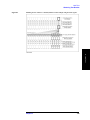
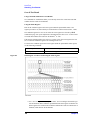
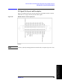
Handler I/O Port Overview. . . . . . . . . . . . . . . . . . . . . . . . . . . . . . . . . . . . . . . . . . . . . . . . . . . . . . . . . . . . . 148
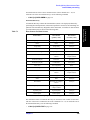
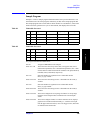
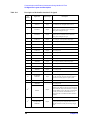
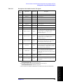
I/O Signal Pin Layout and Description. . . . . . . . . . . . . . . . . . . . . . . . . . . . . . . . . . . . . . . . . . . . . . . . . . . . 149
Inputting/Outputting Data. . . . . . . . . . . . . . . . . . . . . . . . . . . . . . . . . . . . . . . . . . . . . . . . . . . . . . . . . . . . . . 152
Specifying signal direction of port . . . . . . . . . . . . . . . . . . . . . . . . . . . . . . . . . . . . . . . . . . . . . . . . . . . . . 152
Reading data input to port . . . . . . . . . . . . . . . . . . . . . . . . . . . . . . . . . . . . . . . . . . . . . . . . . . . . . . . . . . . . 153
Data output to port. . . . . . . . . . . . . . . . . . . . . . . . . . . . . . . . . . . . . . . . . . . . . . . . . . . . . . . . . . . . . . . . . . 153
Preset states at power-on. . . . . . . . . . . . . . . . . . . . . . . . . . . . . . . . . . . . . . . . . . . . . . . . . . . . . . . . . . . . . . . 154
Timing Chart . . . . . . . . . . . . . . . . . . . . . . . . . . . . . . . . . . . . . . . . . . . . . . . . . . . . . . . . . . . . . . . . . . . . . . . . 155
Electrical Characteristics . . . . . . . . . . . . . . . . . . . . . . . . . . . . . . . . . . . . . . . . . . . . . . . . . . . . . . . . . . . . . . 158
Input signal . . . . . . . . . . . . . . . . . . . . . . . . . . . . . . . . . . . . . . . . . . . . . . . . . . . . . . . . . . . . . . . . . . . . . . . 158
Output signal . . . . . . . . . . . . . . . . . . . . . . . . . . . . . . . . . . . . . . . . . . . . . . . . . . . . . . . . . . . . . . . . . . . . . . 159
Power supply (+5 V) . . . . . . . . . . . . . . . . . . . . . . . . . . . . . . . . . . . . . . . . . . . . . . . . . . . . . . . . . . . . . . . . 159
Sample Program . . . . . . . . . . . . . . . . . . . . . . . . . . . . . . . . . . . . . . . . . . . . . . . . . . . . . . . . . . . . . . . . . . . . . 160
11. Working with Automatic Test Systems
Preventing Erroneous Key Operation on the Front Panel (Key Lock Feature) . . . . . . . . . . . . . . . . . . . . . 162
Improving Command Processing Speed. . . . . . . . . . . . . . . . . . . . . . . . . . . . . . . . . . . . . . . . . . . . . . . . . . . 163
Measurement results (trace) need not to be updated . . . . . . . . . . . . . . . . . . . . . . . . . . . . . . . . . . . . . . . . 163
7
Contents
Measurement results (trace) need to be updated. . . . . . . . . . . . . . . . . . . . . . . . . . . . . . . . . . . . . . . . . . .
Sample program . . . . . . . . . . . . . . . . . . . . . . . . . . . . . . . . . . . . . . . . . . . . . . . . . . . . . . . . . . . . . . . . . . .
Detecting Occurrence of an Error. . . . . . . . . . . . . . . . . . . . . . . . . . . . . . . . . . . . . . . . . . . . . . . . . . . . . . . .
Using the status reporting system . . . . . . . . . . . . . . . . . . . . . . . . . . . . . . . . . . . . . . . . . . . . . . . . . . . . . .
Using the error queue . . . . . . . . . . . . . . . . . . . . . . . . . . . . . . . . . . . . . . . . . . . . . . . . . . . . . . . . . . . . . . .
Sample program . . . . . . . . . . . . . . . . . . . . . . . . . . . . . . . . . . . . . . . . . . . . . . . . . . . . . . . . . . . . . . . . . . .
163
164
166
166
166
167
12. Sample Application Programs
Basic measurement (measuring a band pass filter) . . . . . . . . . . . . . . . . . . . . . . . . . . . . . . . . . . . . . . . . . .
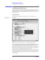
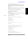
Controlling Using SICL-LAN Server . . . . . . . . . . . . . . . . . . . . . . . . . . . . . . . . . . . . . . . . . . . . . . . . . . . .
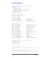
Using VBA macro . . . . . . . . . . . . . . . . . . . . . . . . . . . . . . . . . . . . . . . . . . . . . . . . . . . . . . . . . . . . . . . . .
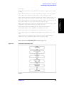
Description of operation in VBA macro. . . . . . . . . . . . . . . . . . . . . . . . . . . . . . . . . . . . . . . . . . . . . . . . .
Controlling Using Telnet Server. . . . . . . . . . . . . . . . . . . . . . . . . . . . . . . . . . . . . . . . . . . . . . . . . . . . . . . . .
Using VBA macro . . . . . . . . . . . . . . . . . . . . . . . . . . . . . . . . . . . . . . . . . . . . . . . . . . . . . . . . . . . . . . . . .
Description of operation in VBA macro. . . . . . . . . . . . . . . . . . . . . . . . . . . . . . . . . . . . . . . . . . . . . . . . .
170
176
176
177
184
184
185
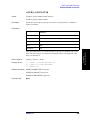
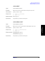
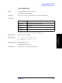
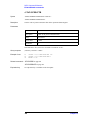
13. SCPI Command Reference
Notational conventions in this command reference . . . . . . . . . . . . . . . . . . . . . . . . . . . . . . . . . . . . . . . . .
Syntax . . . . . . . . . . . . . . . . . . . . . . . . . . . . . . . . . . . . . . . . . . . . . . . . . . . . . . . . . . . . . . . . . . . . . . . . . . .
Description . . . . . . . . . . . . . . . . . . . . . . . . . . . . . . . . . . . . . . . . . . . . . . . . . . . . . . . . . . . . . . . . . . . . . . .
Parameters. . . . . . . . . . . . . . . . . . . . . . . . . . . . . . . . . . . . . . . . . . . . . . . . . . . . . . . . . . . . . . . . . . . . . . . .
Query response . . . . . . . . . . . . . . . . . . . . . . . . . . . . . . . . . . . . . . . . . . . . . . . . . . . . . . . . . . . . . . . . . . . .
Related commands . . . . . . . . . . . . . . . . . . . . . . . . . . . . . . . . . . . . . . . . . . . . . . . . . . . . . . . . . . . . . . . . .
Equivalent key . . . . . . . . . . . . . . . . . . . . . . . . . . . . . . . . . . . . . . . . . . . . . . . . . . . . . . . . . . . . . . . . . . . .
IEEE Common Commands . . . . . . . . . . . . . . . . . . . . . . . . . . . . . . . . . . . . . . . . . . . . . . . . . . . . . . . . . . . .
*CLS . . . . . . . . . . . . . . . . . . . . . . . . . . . . . . . . . . . . . . . . . . . . . . . . . . . . . . . . . . . . . . . . . . . . . . . . . . . .
*ESE . . . . . . . . . . . . . . . . . . . . . . . . . . . . . . . . . . . . . . . . . . . . . . . . . . . . . . . . . . . . . . . . . . . . . . . . . . . .
*ESR? . . . . . . . . . . . . . . . . . . . . . . . . . . . . . . . . . . . . . . . . . . . . . . . . . . . . . . . . . . . . . . . . . . . . . . . . . . .
*IDN? . . . . . . . . . . . . . . . . . . . . . . . . . . . . . . . . . . . . . . . . . . . . . . . . . . . . . . . . . . . . . . . . . . . . . . . . . . .
*OPC. . . . . . . . . . . . . . . . . . . . . . . . . . . . . . . . . . . . . . . . . . . . . . . . . . . . . . . . . . . . . . . . . . . . . . . . . . . .
*OPC? . . . . . . . . . . . . . . . . . . . . . . . . . . . . . . . . . . . . . . . . . . . . . . . . . . . . . . . . . . . . . . . . . . . . . . . . . . .
*OPT? . . . . . . . . . . . . . . . . . . . . . . . . . . . . . . . . . . . . . . . . . . . . . . . . . . . . . . . . . . . . . . . . . . . . . . . . . . .
*RST . . . . . . . . . . . . . . . . . . . . . . . . . . . . . . . . . . . . . . . . . . . . . . . . . . . . . . . . . . . . . . . . . . . . . . . . . . .
*SRE . . . . . . . . . . . . . . . . . . . . . . . . . . . . . . . . . . . . . . . . . . . . . . . . . . . . . . . . . . . . . . . . . . . . . . . . . . . .
*STB? . . . . . . . . . . . . . . . . . . . . . . . . . . . . . . . . . . . . . . . . . . . . . . . . . . . . . . . . . . . . . . . . . . . . . . . . . . .
*TRG . . . . . . . . . . . . . . . . . . . . . . . . . . . . . . . . . . . . . . . . . . . . . . . . . . . . . . . . . . . . . . . . . . . . . . . . . . .
*WAI . . . . . . . . . . . . . . . . . . . . . . . . . . . . . . . . . . . . . . . . . . . . . . . . . . . . . . . . . . . . . . . . . . . . . . . . . . . .
E5061A/E5062A commands . . . . . . . . . . . . . . . . . . . . . . . . . . . . . . . . . . . . . . . . . . . . . . . . . . . . . . . . . . .
:ABOR . . . . . . . . . . . . . . . . . . . . . . . . . . . . . . . . . . . . . . . . . . . . . . . . . . . . . . . . . . . . . . . . . . . . . . . . . .
:CALC{1-4}:BLIM . . . . . . . . . . . . . . . . . . . . . . . . . . . . . . . . . . . . . . . . . . . . . . . . . . . . . . . . . . . . . . . .
:CALC{1-4}:BLIM:DB . . . . . . . . . . . . . . . . . . . . . . . . . . . . . . . . . . . . . . . . . . . . . . . . . . . . . . . . . . . . .
:CALC{1-4}:BLIM:DISP:MARK . . . . . . . . . . . . . . . . . . . . . . . . . . . . . . . . . . . . . . . . . . . . . . . . . . . . .
:CALC{1-4}:BLIM:DISP:VAL . . . . . . . . . . . . . . . . . . . . . . . . . . . . . . . . . . . . . . . . . . . . . . . . . . . . . . .
:CALC{1-4}:BLIM:FAIL? . . . . . . . . . . . . . . . . . . . . . . . . . . . . . . . . . . . . . . . . . . . . . . . . . . . . . . . . . . .
:CALC{1-4}:BLIM:MAX . . . . . . . . . . . . . . . . . . . . . . . . . . . . . . . . . . . . . . . . . . . . . . . . . . . . . . . . . . .
:CALC{1-4}:BLIM:MIN . . . . . . . . . . . . . . . . . . . . . . . . . . . . . . . . . . . . . . . . . . . . . . . . . . . . . . . . . . . .
:CALC{1-4}:BLIM:REP? . . . . . . . . . . . . . . . . . . . . . . . . . . . . . . . . . . . . . . . . . . . . . . . . . . . . . . . . . . .
:CALC{1-4}:CONV . . . . . . . . . . . . . . . . . . . . . . . . . . . . . . . . . . . . . . . . . . . . . . . . . . . . . . . . . . . . . . . .
194
194
194
195
195
195
195
196
196
197
197
198
198
198
199
199
200
201
201
201
202
202
203
204
205
206
207
208
209
210
211
8
Contents
:CALC{1-4}:CONV:FUNC . . . . . . . . . . . . . . . . . . . . . . . . . . . . . . . . . . . . . . . . . . . . . . . . . . . . . . . . . . 212
:CALC{1-4}:CORR:EDEL:TIME . . . . . . . . . . . . . . . . . . . . . . . . . . . . . . . . . . . . . . . . . . . . . . . . . . . . . 213
:CALC{1-4}:CORR:OFFS:PHAS . . . . . . . . . . . . . . . . . . . . . . . . . . . . . . . . . . . . . . . . . . . . . . . . . . . . . 214
:CALC{1-4}:DATA:FDAT . . . . . . . . . . . . . . . . . . . . . . . . . . . . . . . . . . . . . . . . . . . . . . . . . . . . . . . . . . . 215
:CALC{1-4}:DATA:FMEM . . . . . . . . . . . . . . . . . . . . . . . . . . . . . . . . . . . . . . . . . . . . . . . . . . . . . . . . . . 216
:CALC{1-4}:DATA:SDAT . . . . . . . . . . . . . . . . . . . . . . . . . . . . . . . . . . . . . . . . . . . . . . . . . . . . . . . . . . . 217
:CALC{1-4}:DATA:SMEM . . . . . . . . . . . . . . . . . . . . . . . . . . . . . . . . . . . . . . . . . . . . . . . . . . . . . . . . . . 218
:CALC{1-4}:FORM . . . . . . . . . . . . . . . . . . . . . . . . . . . . . . . . . . . . . . . . . . . . . . . . . . . . . . . . . . . . . . . . 219
:CALC{1-4}:FUNC:DATA? . . . . . . . . . . . . . . . . . . . . . . . . . . . . . . . . . . . . . . . . . . . . . . . . . . . . . . . . . . 221
:CALC{1-4}:FUNC:DOM . . . . . . . . . . . . . . . . . . . . . . . . . . . . . . . . . . . . . . . . . . . . . . . . . . . . . . . . . . . 222
:CALC{1-4}:FUNC:DOM:COUP . . . . . . . . . . . . . . . . . . . . . . . . . . . . . . . . . . . . . . . . . . . . . . . . . . . . . 223
:CALC{1-4}:FUNC:DOM:STAR. . . . . . . . . . . . . . . . . . . . . . . . . . . . . . . . . . . . . . . . . . . . . . . . . . . . . . 224
:CALC{1-4}:FUNC:DOM:STOP . . . . . . . . . . . . . . . . . . . . . . . . . . . . . . . . . . . . . . . . . . . . . . . . . . . . . . 225
:CALC{1-4}:FUNC:EXEC. . . . . . . . . . . . . . . . . . . . . . . . . . . . . . . . . . . . . . . . . . . . . . . . . . . . . . . . . . . 225
:CALC{1-4}:FUNC:PEXC. . . . . . . . . . . . . . . . . . . . . . . . . . . . . . . . . . . . . . . . . . . . . . . . . . . . . . . . . . . 226
:CALC{1-4}:FUNC:POIN? . . . . . . . . . . . . . . . . . . . . . . . . . . . . . . . . . . . . . . . . . . . . . . . . . . . . . . . . . . 227
:CALC{1-4}:FUNC:PPOL . . . . . . . . . . . . . . . . . . . . . . . . . . . . . . . . . . . . . . . . . . . . . . . . . . . . . . . . . . . 228
:CALC{1-4}:FUNC:TARG . . . . . . . . . . . . . . . . . . . . . . . . . . . . . . . . . . . . . . . . . . . . . . . . . . . . . . . . . . 229
:CALC{1-4}:FUNC:TTR . . . . . . . . . . . . . . . . . . . . . . . . . . . . . . . . . . . . . . . . . . . . . . . . . . . . . . . . . . . . 230
:CALC{1-4}:FUNC:TYPE . . . . . . . . . . . . . . . . . . . . . . . . . . . . . . . . . . . . . . . . . . . . . . . . . . . . . . . . . . . 231
:CALC{1-4}:LIM . . . . . . . . . . . . . . . . . . . . . . . . . . . . . . . . . . . . . . . . . . . . . . . . . . . . . . . . . . . . . . . . . . 232
:CALC{1-4}:LIM:DATA . . . . . . . . . . . . . . . . . . . . . . . . . . . . . . . . . . . . . . . . . . . . . . . . . . . . . . . . . . . . 233
:CALC{1-4}:LIM:DISP . . . . . . . . . . . . . . . . . . . . . . . . . . . . . . . . . . . . . . . . . . . . . . . . . . . . . . . . . . . . . 235
:CALC{1-4}:LIM:DISP:CLIP . . . . . . . . . . . . . . . . . . . . . . . . . . . . . . . . . . . . . . . . . . . . . . . . . . . . . . . . 236
:CALC{1-4}:LIM:FAIL? . . . . . . . . . . . . . . . . . . . . . . . . . . . . . . . . . . . . . . . . . . . . . . . . . . . . . . . . . . . . 237
:CALC{1-4}:LIM:OFFS:AMPL. . . . . . . . . . . . . . . . . . . . . . . . . . . . . . . . . . . . . . . . . . . . . . . . . . . . . . . 238
:CALC{1-4}:LIM:OFFS:MARK . . . . . . . . . . . . . . . . . . . . . . . . . . . . . . . . . . . . . . . . . . . . . . . . . . . . . . 239
:CALC{1-4}:LIM:OFFS:STIM . . . . . . . . . . . . . . . . . . . . . . . . . . . . . . . . . . . . . . . . . . . . . . . . . . . . . . . 240
:CALC{1-4}:LIM:REP:ALL? . . . . . . . . . . . . . . . . . . . . . . . . . . . . . . . . . . . . . . . . . . . . . . . . . . . . . . . . 241
:CALC{1-4}:LIM:REP? . . . . . . . . . . . . . . . . . . . . . . . . . . . . . . . . . . . . . . . . . . . . . . . . . . . . . . . . . . . . . 242
:CALC{1-4}:LIM:REP:POIN?. . . . . . . . . . . . . . . . . . . . . . . . . . . . . . . . . . . . . . . . . . . . . . . . . . . . . . . . 242
:CALC{1-4}:MARK:BWID . . . . . . . . . . . . . . . . . . . . . . . . . . . . . . . . . . . . . . . . . . . . . . . . . . . . . . . . . . 243
:CALC{1-4}:MARK:COUP . . . . . . . . . . . . . . . . . . . . . . . . . . . . . . . . . . . . . . . . . . . . . . . . . . . . . . . . . . 244
:CALC{1-4}:MARK:FUNC:DOM. . . . . . . . . . . . . . . . . . . . . . . . . . . . . . . . . . . . . . . . . . . . . . . . . . . . . 245
:CALC{1-4}:MARK:FUNC:DOM:COUP. . . . . . . . . . . . . . . . . . . . . . . . . . . . . . . . . . . . . . . . . . . . . . . 246
:CALC{1-4}:MARK:FUNC:DOM:STAR . . . . . . . . . . . . . . . . . . . . . . . . . . . . . . . . . . . . . . . . . . . . . . . 247
:CALC{1-4}:MARK:FUNC:DOM:STOP . . . . . . . . . . . . . . . . . . . . . . . . . . . . . . . . . . . . . . . . . . . . . . . 248
:CALC{1-4}:MARK:FUNC:MULT:PEXC . . . . . . . . . . . . . . . . . . . . . . . . . . . . . . . . . . . . . . . . . . . . . . 249
:CALC{1-4}:MARK:FUNC:MULT:PPOL . . . . . . . . . . . . . . . . . . . . . . . . . . . . . . . . . . . . . . . . . . . . . . 250
:CALC{1-4}:MARK:FUNC:MULT:TARG . . . . . . . . . . . . . . . . . . . . . . . . . . . . . . . . . . . . . . . . . . . . . . 251
:CALC{1-4}:MARK:FUNC:MULT:TRAC . . . . . . . . . . . . . . . . . . . . . . . . . . . . . . . . . . . . . . . . . . . . . . 252
:CALC{1-4}:MARK:FUNC:MULT:TTR . . . . . . . . . . . . . . . . . . . . . . . . . . . . . . . . . . . . . . . . . . . . . . . 253
:CALC{1-4}:MARK:FUNC:MULT:TYPE . . . . . . . . . . . . . . . . . . . . . . . . . . . . . . . . . . . . . . . . . . . . . . 254
:CALC{1-4}:MARK:MATH:FLAT . . . . . . . . . . . . . . . . . . . . . . . . . . . . . . . . . . . . . . . . . . . . . . . . . . . . 255
:CALC{1-4}:MARK:MATH:FLAT:DATA?. . . . . . . . . . . . . . . . . . . . . . . . . . . . . . . . . . . . . . . . . . . . . . 256
:CALC{1-4}:MARK:MATH:FST . . . . . . . . . . . . . . . . . . . . . . . . . . . . . . . . . . . . . . . . . . . . . . . . . . . . . 257
:CALC{1-4}:MARK:MATH:FST:DATA? . . . . . . . . . . . . . . . . . . . . . . . . . . . . . . . . . . . . . . . . . . . . . . . 258
:CALC{1-4}:MARK:MATH:STAT . . . . . . . . . . . . . . . . . . . . . . . . . . . . . . . . . . . . . . . . . . . . . . . . . . . . 259
:CALC{1-4}:MARK:MATH:STAT:DATA? . . . . . . . . . . . . . . . . . . . . . . . . . . . . . . . . . . . . . . . . . . . . . . 260
9
Contents
:CALC{1-4}:MARK:NOTC . . . . . . . . . . . . . . . . . . . . . . . . . . . . . . . . . . . . . . . . . . . . . . . . . . . . . . . . .
:CALC{1-4}:MARK:REF . . . . . . . . . . . . . . . . . . . . . . . . . . . . . . . . . . . . . . . . . . . . . . . . . . . . . . . . . . .
:CALC{1-4}:MARK{1-10} . . . . . . . . . . . . . . . . . . . . . . . . . . . . . . . . . . . . . . . . . . . . . . . . . . . . . . . . . .
:CALC{1-4}:MARK{1-10}:ACT . . . . . . . . . . . . . . . . . . . . . . . . . . . . . . . . . . . . . . . . . . . . . . . . . . . . .
:CALC{1-4}:MARK{1-10}:BWID:DATA? . . . . . . . . . . . . . . . . . . . . . . . . . . . . . . . . . . . . . . . . . . . . .
:CALC{1-4}:MARK{1-10}:BWID:THR . . . . . . . . . . . . . . . . . . . . . . . . . . . . . . . . . . . . . . . . . . . . . . .
:CALC{1-4}:MARK{1-10}:DISC . . . . . . . . . . . . . . . . . . . . . . . . . . . . . . . . . . . . . . . . . . . . . . . . . . . . .
:CALC{1-4}:MARK{1-10}:FUNC:EXEC . . . . . . . . . . . . . . . . . . . . . . . . . . . . . . . . . . . . . . . . . . . . . .
:CALC{1-4}:MARK{1-10}:FUNC:PEXC . . . . . . . . . . . . . . . . . . . . . . . . . . . . . . . . . . . . . . . . . . . . . .
:CALC{1-4}:MARK{1-10}:FUNC:PPOL. . . . . . . . . . . . . . . . . . . . . . . . . . . . . . . . . . . . . . . . . . . . . . .
:CALC{1-4}:MARK{1-10}:FUNC:TARG . . . . . . . . . . . . . . . . . . . . . . . . . . . . . . . . . . . . . . . . . . . . . .
:CALC{1-4}:MARK{1-10}:FUNC:TRAC . . . . . . . . . . . . . . . . . . . . . . . . . . . . . . . . . . . . . . . . . . . . . .
:CALC{1-4}:MARK{1-10}:FUNC:TTR. . . . . . . . . . . . . . . . . . . . . . . . . . . . . . . . . . . . . . . . . . . . . . . .
:CALC{1-4}:MARK{1-10}:FUNC:TYPE . . . . . . . . . . . . . . . . . . . . . . . . . . . . . . . . . . . . . . . . . . . . . .
:CALC{1-4}:MARK{1-10}:NOTC:DATA? . . . . . . . . . . . . . . . . . . . . . . . . . . . . . . . . . . . . . . . . . . . . .
:CALC{1-4}:MARK{1-10}:NOTC:THR . . . . . . . . . . . . . . . . . . . . . . . . . . . . . . . . . . . . . . . . . . . . . . .
:CALC{1-4}:MARK{1-10}:SET . . . . . . . . . . . . . . . . . . . . . . . . . . . . . . . . . . . . . . . . . . . . . . . . . . . . . .
:CALC{1-4}:MARK{1-10}:X . . . . . . . . . . . . . . . . . . . . . . . . . . . . . . . . . . . . . . . . . . . . . . . . . . . . . . . .
:CALC{1-4}:MARK{1-10}:Y? . . . . . . . . . . . . . . . . . . . . . . . . . . . . . . . . . . . . . . . . . . . . . . . . . . . . . . .
:CALC{1-4}:MATH:FUNC . . . . . . . . . . . . . . . . . . . . . . . . . . . . . . . . . . . . . . . . . . . . . . . . . . . . . . . . . .
:CALC{1-4}:MATH:MEM . . . . . . . . . . . . . . . . . . . . . . . . . . . . . . . . . . . . . . . . . . . . . . . . . . . . . . . . . .
:CALC{1-4}:MST . . . . . . . . . . . . . . . . . . . . . . . . . . . . . . . . . . . . . . . . . . . . . . . . . . . . . . . . . . . . . . . . .
:CALC{1-4}:MST:DATA? . . . . . . . . . . . . . . . . . . . . . . . . . . . . . . . . . . . . . . . . . . . . . . . . . . . . . . . . . . .
:CALC{1-4}:PAR:COUN. . . . . . . . . . . . . . . . . . . . . . . . . . . . . . . . . . . . . . . . . . . . . . . . . . . . . . . . . . . .
:CALC{1-4}:PAR{1-4}:DEF . . . . . . . . . . . . . . . . . . . . . . . . . . . . . . . . . . . . . . . . . . . . . . . . . . . . . . . . .
:CALC{1-4}:PAR{1-4}:SEL . . . . . . . . . . . . . . . . . . . . . . . . . . . . . . . . . . . . . . . . . . . . . . . . . . . . . . . . .
:CALC{1-4}:RLIM . . . . . . . . . . . . . . . . . . . . . . . . . . . . . . . . . . . . . . . . . . . . . . . . . . . . . . . . . . . . . . . .
:CALC{1-4}:RLIM:DATA . . . . . . . . . . . . . . . . . . . . . . . . . . . . . . . . . . . . . . . . . . . . . . . . . . . . . . . . . . .
:CALC{1-4}:RLIM:DISP:LINE . . . . . . . . . . . . . . . . . . . . . . . . . . . . . . . . . . . . . . . . . . . . . . . . . . . . . .
:CALC{1-4}:RLIM:DISP:SEL . . . . . . . . . . . . . . . . . . . . . . . . . . . . . . . . . . . . . . . . . . . . . . . . . . . . . . .
:CALC{1-4}:RLIM:DISP:VAL . . . . . . . . . . . . . . . . . . . . . . . . . . . . . . . . . . . . . . . . . . . . . . . . . . . . . . .
:CALC{1-4}:RLIM:FAIL? . . . . . . . . . . . . . . . . . . . . . . . . . . . . . . . . . . . . . . . . . . . . . . . . . . . . . . . . . . .
:CALC{1-4}:RLIM:REP? . . . . . . . . . . . . . . . . . . . . . . . . . . . . . . . . . . . . . . . . . . . . . . . . . . . . . . . . . . .
:CALC{1-4}:SMO . . . . . . . . . . . . . . . . . . . . . . . . . . . . . . . . . . . . . . . . . . . . . . . . . . . . . . . . . . . . . . . . .
:CALC{1-4}:SMO:APER . . . . . . . . . . . . . . . . . . . . . . . . . . . . . . . . . . . . . . . . . . . . . . . . . . . . . . . . . . .
:CONT:HAND:A . . . . . . . . . . . . . . . . . . . . . . . . . . . . . . . . . . . . . . . . . . . . . . . . . . . . . . . . . . . . . . . . . .
:CONT:HAND:B . . . . . . . . . . . . . . . . . . . . . . . . . . . . . . . . . . . . . . . . . . . . . . . . . . . . . . . . . . . . . . . . . .
:CONT:HAND:C . . . . . . . . . . . . . . . . . . . . . . . . . . . . . . . . . . . . . . . . . . . . . . . . . . . . . . . . . . . . . . . . . .
:CONT:HAND:C:MODE . . . . . . . . . . . . . . . . . . . . . . . . . . . . . . . . . . . . . . . . . . . . . . . . . . . . . . . . . . . .
:CONT:HAND:D . . . . . . . . . . . . . . . . . . . . . . . . . . . . . . . . . . . . . . . . . . . . . . . . . . . . . . . . . . . . . . . . . .
:CONT:HAND:D:MODE . . . . . . . . . . . . . . . . . . . . . . . . . . . . . . . . . . . . . . . . . . . . . . . . . . . . . . . . . . . .
:CONT:HAND:E . . . . . . . . . . . . . . . . . . . . . . . . . . . . . . . . . . . . . . . . . . . . . . . . . . . . . . . . . . . . . . . . . .
:CONT:HAND:F. . . . . . . . . . . . . . . . . . . . . . . . . . . . . . . . . . . . . . . . . . . . . . . . . . . . . . . . . . . . . . . . . . .
:CONT:HAND:IND:STAT . . . . . . . . . . . . . . . . . . . . . . . . . . . . . . . . . . . . . . . . . . . . . . . . . . . . . . . . . . .
:CONT:HAND:OUTP{1-2} . . . . . . . . . . . . . . . . . . . . . . . . . . . . . . . . . . . . . . . . . . . . . . . . . . . . . . . . . .
:CONT:HAND:RTR:STAT . . . . . . . . . . . . . . . . . . . . . . . . . . . . . . . . . . . . . . . . . . . . . . . . . . . . . . . . . . .
:DISP:ANN:FREQ . . . . . . . . . . . . . . . . . . . . . . . . . . . . . . . . . . . . . . . . . . . . . . . . . . . . . . . . . . . . . . . . .
:DISP:CCL . . . . . . . . . . . . . . . . . . . . . . . . . . . . . . . . . . . . . . . . . . . . . . . . . . . . . . . . . . . . . . . . . . . . . . .
:DISP:CLOC . . . . . . . . . . . . . . . . . . . . . . . . . . . . . . . . . . . . . . . . . . . . . . . . . . . . . . . . . . . . . . . . . . . . . .
10
261
262
263
264
265
266
267
268
269
270
271
272
273
274
276
277
278
279
280
281
281
282
283
284
285
286
286
287
288
289
290
291
292
293
294
295
295
296
297
298
299
300
301
302
302
303
304
304
305
Contents
:DISP:COL{1-2}:BACK. . . . . . . . . . . . . . . . . . . . . . . . . . . . . . . . . . . . . . . . . . . . . . . . . . . . . . . . . . . . . 306
:DISP:COL{1-2}:GRAT{1-2} . . . . . . . . . . . . . . . . . . . . . . . . . . . . . . . . . . . . . . . . . . . . . . . . . . . . . . . . 307
:DISP:COL{1-2}:LIM{1-2} . . . . . . . . . . . . . . . . . . . . . . . . . . . . . . . . . . . . . . . . . . . . . . . . . . . . . . . . . . 308
:DISP:COL{1-2}:RES . . . . . . . . . . . . . . . . . . . . . . . . . . . . . . . . . . . . . . . . . . . . . . . . . . . . . . . . . . . . . . 308
:DISP:COL{1-2}:TRAC{1-4}:DATA . . . . . . . . . . . . . . . . . . . . . . . . . . . . . . . . . . . . . . . . . . . . . . . . . . 309
:DISP:COL{1-2}:TRAC{1-4}:MEM . . . . . . . . . . . . . . . . . . . . . . . . . . . . . . . . . . . . . . . . . . . . . . . . . . . 310
:DISP:ECHO . . . . . . . . . . . . . . . . . . . . . . . . . . . . . . . . . . . . . . . . . . . . . . . . . . . . . . . . . . . . . . . . . . . . . . 311
:DISP:ECHO:CLE . . . . . . . . . . . . . . . . . . . . . . . . . . . . . . . . . . . . . . . . . . . . . . . . . . . . . . . . . . . . . . . . . 311
:DISP:ENAB . . . . . . . . . . . . . . . . . . . . . . . . . . . . . . . . . . . . . . . . . . . . . . . . . . . . . . . . . . . . . . . . . . . . . . 312
:DISP:FSIG . . . . . . . . . . . . . . . . . . . . . . . . . . . . . . . . . . . . . . . . . . . . . . . . . . . . . . . . . . . . . . . . . . . . . . . 313
:DISP:IMAG . . . . . . . . . . . . . . . . . . . . . . . . . . . . . . . . . . . . . . . . . . . . . . . . . . . . . . . . . . . . . . . . . . . . . . 313
:DISP:MAX. . . . . . . . . . . . . . . . . . . . . . . . . . . . . . . . . . . . . . . . . . . . . . . . . . . . . . . . . . . . . . . . . . . . . . . 314
:DISP:SKEY . . . . . . . . . . . . . . . . . . . . . . . . . . . . . . . . . . . . . . . . . . . . . . . . . . . . . . . . . . . . . . . . . . . . . . 314
:DISP:SPL . . . . . . . . . . . . . . . . . . . . . . . . . . . . . . . . . . . . . . . . . . . . . . . . . . . . . . . . . . . . . . . . . . . . . . . . 315
:DISP:TABL . . . . . . . . . . . . . . . . . . . . . . . . . . . . . . . . . . . . . . . . . . . . . . . . . . . . . . . . . . . . . . . . . . . . . . 316
:DISP:TABL:TYPE. . . . . . . . . . . . . . . . . . . . . . . . . . . . . . . . . . . . . . . . . . . . . . . . . . . . . . . . . . . . . . . . . 317
:DISP:UPD . . . . . . . . . . . . . . . . . . . . . . . . . . . . . . . . . . . . . . . . . . . . . . . . . . . . . . . . . . . . . . . . . . . . . . . 318
:DISP:WIND{1-4}:ACT. . . . . . . . . . . . . . . . . . . . . . . . . . . . . . . . . . . . . . . . . . . . . . . . . . . . . . . . . . . . . 318
:DISP:WIND{1-4}:ANN:MARK:ALIG . . . . . . . . . . . . . . . . . . . . . . . . . . . . . . . . . . . . . . . . . . . . . . . . 319
:DISP:WIND{1-4}:ANN:MARK:SING. . . . . . . . . . . . . . . . . . . . . . . . . . . . . . . . . . . . . . . . . . . . . . . . . 320
:DISP:WIND{1-4}:LAB. . . . . . . . . . . . . . . . . . . . . . . . . . . . . . . . . . . . . . . . . . . . . . . . . . . . . . . . . . . . . 321
:DISP:WIND{1-4}:MAX . . . . . . . . . . . . . . . . . . . . . . . . . . . . . . . . . . . . . . . . . . . . . . . . . . . . . . . . . . . . 322
:DISP:WIND{1-4}:SPL . . . . . . . . . . . . . . . . . . . . . . . . . . . . . . . . . . . . . . . . . . . . . . . . . . . . . . . . . . . . . 323
:DISP:WIND{1-4}:TITL . . . . . . . . . . . . . . . . . . . . . . . . . . . . . . . . . . . . . . . . . . . . . . . . . . . . . . . . . . . . 324
:DISP:WIND{1-4}:TITL:DATA. . . . . . . . . . . . . . . . . . . . . . . . . . . . . . . . . . . . . . . . . . . . . . . . . . . . . . . 324
:DISP:WIND{1-4}:TRAC{1-4}:ANN:MARK:POS:X . . . . . . . . . . . . . . . . . . . . . . . . . . . . . . . . . . . . . 325
:DISP:WIND{1-4}:TRAC{1-4}:ANN:MARK:POS:Y . . . . . . . . . . . . . . . . . . . . . . . . . . . . . . . . . . . . . 326
:DISP:WIND{1-4}:TRAC{1-4}:ANN:YAX:MODE . . . . . . . . . . . . . . . . . . . . . . . . . . . . . . . . . . . . . . . 327
:DISP:WIND{1-4}:TRAC{1-4}:MEM . . . . . . . . . . . . . . . . . . . . . . . . . . . . . . . . . . . . . . . . . . . . . . . . . 328
:DISP:WIND{1-4}:TRAC{1-4}:STAT. . . . . . . . . . . . . . . . . . . . . . . . . . . . . . . . . . . . . . . . . . . . . . . . . . 329
:DISP:WIND{1-4}:TRAC{1-4}:Y:AUTO . . . . . . . . . . . . . . . . . . . . . . . . . . . . . . . . . . . . . . . . . . . . . . . 329
:DISP:WIND{1-4}:TRAC{1-4}:Y:PDIV . . . . . . . . . . . . . . . . . . . . . . . . . . . . . . . . . . . . . . . . . . . . . . . . 330
:DISP:WIND{1-4}:TRAC{1-4}:Y:RLEV . . . . . . . . . . . . . . . . . . . . . . . . . . . . . . . . . . . . . . . . . . . . . . . 331
:DISP:WIND{1-4}:TRAC{1-4}:Y:RPOS . . . . . . . . . . . . . . . . . . . . . . . . . . . . . . . . . . . . . . . . . . . . . . . 332
:DISP:WIND{1-4}:TRAC{1-4}:Y:TRAC:FREQ . . . . . . . . . . . . . . . . . . . . . . . . . . . . . . . . . . . . . . . . . 333
:DISP:WIND{1-4}:TRAC{1-4}:Y:TRAC:MODE. . . . . . . . . . . . . . . . . . . . . . . . . . . . . . . . . . . . . . . . . 334
:DISP:WIND{1-4}:X:SPAC . . . . . . . . . . . . . . . . . . . . . . . . . . . . . . . . . . . . . . . . . . . . . . . . . . . . . . . . . . 335
:DISP:WIND{1-4}:Y:DIV . . . . . . . . . . . . . . . . . . . . . . . . . . . . . . . . . . . . . . . . . . . . . . . . . . . . . . . . . . . 336
:FORM:BORD . . . . . . . . . . . . . . . . . . . . . . . . . . . . . . . . . . . . . . . . . . . . . . . . . . . . . . . . . . . . . . . . . . . . 337
:FORM:DATA . . . . . . . . . . . . . . . . . . . . . . . . . . . . . . . . . . . . . . . . . . . . . . . . . . . . . . . . . . . . . . . . . . . . . 338
:HCOP . . . . . . . . . . . . . . . . . . . . . . . . . . . . . . . . . . . . . . . . . . . . . . . . . . . . . . . . . . . . . . . . . . . . . . . . . . . 339
:HCOP:ABOR. . . . . . . . . . . . . . . . . . . . . . . . . . . . . . . . . . . . . . . . . . . . . . . . . . . . . . . . . . . . . . . . . . . . . 339
:HCOP:IMAG . . . . . . . . . . . . . . . . . . . . . . . . . . . . . . . . . . . . . . . . . . . . . . . . . . . . . . . . . . . . . . . . . . . . . 339
:INIT{1-4}. . . . . . . . . . . . . . . . . . . . . . . . . . . . . . . . . . . . . . . . . . . . . . . . . . . . . . . . . . . . . . . . . . . . . . . . 340
:INIT{1-4}:CONT. . . . . . . . . . . . . . . . . . . . . . . . . . . . . . . . . . . . . . . . . . . . . . . . . . . . . . . . . . . . . . . . . . 341
:MMEM:CAT? . . . . . . . . . . . . . . . . . . . . . . . . . . . . . . . . . . . . . . . . . . . . . . . . . . . . . . . . . . . . . . . . . . . . 342
:MMEM:COPY. . . . . . . . . . . . . . . . . . . . . . . . . . . . . . . . . . . . . . . . . . . . . . . . . . . . . . . . . . . . . . . . . . . . 343
:MMEM:DEL . . . . . . . . . . . . . . . . . . . . . . . . . . . . . . . . . . . . . . . . . . . . . . . . . . . . . . . . . . . . . . . . . . . . . 344
:MMEM:LOAD . . . . . . . . . . . . . . . . . . . . . . . . . . . . . . . . . . . . . . . . . . . . . . . . . . . . . . . . . . . . . . . . . . . 345
11
Contents
:MMEM:LOAD:CHAN . . . . . . . . . . . . . . . . . . . . . . . . . . . . . . . . . . . . . . . . . . . . . . . . . . . . . . . . . . . . .
:MMEM:LOAD:CHAN:COEF . . . . . . . . . . . . . . . . . . . . . . . . . . . . . . . . . . . . . . . . . . . . . . . . . . . . . . .
:MMEM:LOAD:LIM . . . . . . . . . . . . . . . . . . . . . . . . . . . . . . . . . . . . . . . . . . . . . . . . . . . . . . . . . . . . . . .
:MMEM:LOAD:PROG . . . . . . . . . . . . . . . . . . . . . . . . . . . . . . . . . . . . . . . . . . . . . . . . . . . . . . . . . . . . .
:MMEM:LOAD:RLIM . . . . . . . . . . . . . . . . . . . . . . . . . . . . . . . . . . . . . . . . . . . . . . . . . . . . . . . . . . . . . .
:MMEM:LOAD:SEGM . . . . . . . . . . . . . . . . . . . . . . . . . . . . . . . . . . . . . . . . . . . . . . . . . . . . . . . . . . . . .
:MMEM:MDIR. . . . . . . . . . . . . . . . . . . . . . . . . . . . . . . . . . . . . . . . . . . . . . . . . . . . . . . . . . . . . . . . . . . .
:MMEM:STOR . . . . . . . . . . . . . . . . . . . . . . . . . . . . . . . . . . . . . . . . . . . . . . . . . . . . . . . . . . . . . . . . . . . .
:MMEM:STOR:CHAN. . . . . . . . . . . . . . . . . . . . . . . . . . . . . . . . . . . . . . . . . . . . . . . . . . . . . . . . . . . . . .
:MMEM:STOR:CHAN:CLE . . . . . . . . . . . . . . . . . . . . . . . . . . . . . . . . . . . . . . . . . . . . . . . . . . . . . . . . .
:MMEM:STOR:CHAN:COEF . . . . . . . . . . . . . . . . . . . . . . . . . . . . . . . . . . . . . . . . . . . . . . . . . . . . . . . .
:MMEM:STOR:FDAT . . . . . . . . . . . . . . . . . . . . . . . . . . . . . . . . . . . . . . . . . . . . . . . . . . . . . . . . . . . . . .
:MMEM:STOR:IMAG . . . . . . . . . . . . . . . . . . . . . . . . . . . . . . . . . . . . . . . . . . . . . . . . . . . . . . . . . . . . . .
:MMEM:STOR:LIM. . . . . . . . . . . . . . . . . . . . . . . . . . . . . . . . . . . . . . . . . . . . . . . . . . . . . . . . . . . . . . . .
:MMEM:STOR:PROG . . . . . . . . . . . . . . . . . . . . . . . . . . . . . . . . . . . . . . . . . . . . . . . . . . . . . . . . . . . . . .
:MMEM:STOR:RLIM . . . . . . . . . . . . . . . . . . . . . . . . . . . . . . . . . . . . . . . . . . . . . . . . . . . . . . . . . . . . . .
:MMEM:STOR:SALL . . . . . . . . . . . . . . . . . . . . . . . . . . . . . . . . . . . . . . . . . . . . . . . . . . . . . . . . . . . . . .
:MMEM:STOR:SEGM. . . . . . . . . . . . . . . . . . . . . . . . . . . . . . . . . . . . . . . . . . . . . . . . . . . . . . . . . . . . . .
:MMEM:STOR:STYP . . . . . . . . . . . . . . . . . . . . . . . . . . . . . . . . . . . . . . . . . . . . . . . . . . . . . . . . . . . . . .
:MMEM:TRAN . . . . . . . . . . . . . . . . . . . . . . . . . . . . . . . . . . . . . . . . . . . . . . . . . . . . . . . . . . . . . . . . . . .
:OUTP . . . . . . . . . . . . . . . . . . . . . . . . . . . . . . . . . . . . . . . . . . . . . . . . . . . . . . . . . . . . . . . . . . . . . . . . . . .
:PROG:CAT? . . . . . . . . . . . . . . . . . . . . . . . . . . . . . . . . . . . . . . . . . . . . . . . . . . . . . . . . . . . . . . . . . . . . .
:PROG:NAME . . . . . . . . . . . . . . . . . . . . . . . . . . . . . . . . . . . . . . . . . . . . . . . . . . . . . . . . . . . . . . . . . . . .
:PROG:STAT . . . . . . . . . . . . . . . . . . . . . . . . . . . . . . . . . . . . . . . . . . . . . . . . . . . . . . . . . . . . . . . . . . . . .
:SENS:CORR:COLL:ECAL:PATH? . . . . . . . . . . . . . . . . . . . . . . . . . . . . . . . . . . . . . . . . . . . . . . . . . . .
:SENS:CORR:IMP . . . . . . . . . . . . . . . . . . . . . . . . . . . . . . . . . . . . . . . . . . . . . . . . . . . . . . . . . . . . . . . . .
:SENS{1-4}:AVER:CLE . . . . . . . . . . . . . . . . . . . . . . . . . . . . . . . . . . . . . . . . . . . . . . . . . . . . . . . . . . . .
:SENS{1-4}:AVER . . . . . . . . . . . . . . . . . . . . . . . . . . . . . . . . . . . . . . . . . . . . . . . . . . . . . . . . . . . . . . . . .
:SENS{1-4}:AVER:COUN . . . . . . . . . . . . . . . . . . . . . . . . . . . . . . . . . . . . . . . . . . . . . . . . . . . . . . . . . .
:SENS{1-4}:BAND . . . . . . . . . . . . . . . . . . . . . . . . . . . . . . . . . . . . . . . . . . . . . . . . . . . . . . . . . . . . . . . .
:SENS{1-4}:BWID. . . . . . . . . . . . . . . . . . . . . . . . . . . . . . . . . . . . . . . . . . . . . . . . . . . . . . . . . . . . . . . . .
:SENS{1-4}:CORR:CLE . . . . . . . . . . . . . . . . . . . . . . . . . . . . . . . . . . . . . . . . . . . . . . . . . . . . . . . . . . . .
:SENS{1-4}:CORR:COEF? . . . . . . . . . . . . . . . . . . . . . . . . . . . . . . . . . . . . . . . . . . . . . . . . . . . . . . . . . .
:SENS{1-4}:CORR:COLL:CKIT . . . . . . . . . . . . . . . . . . . . . . . . . . . . . . . . . . . . . . . . . . . . . . . . . . . . .
:SENS{1-4}:CORR:COLL:CKIT:LAB . . . . . . . . . . . . . . . . . . . . . . . . . . . . . . . . . . . . . . . . . . . . . . . . .
:SENS{1-4}:CORR:COLL:CKIT:ORD:LOAD. . . . . . . . . . . . . . . . . . . . . . . . . . . . . . . . . . . . . . . . . . .
:SENS{1-4}:CORR:COLL:CKIT:ORD:OPEN . . . . . . . . . . . . . . . . . . . . . . . . . . . . . . . . . . . . . . . . . . .
:SENS{1-4}:CORR:COLL:CKIT:ORD:SHOR . . . . . . . . . . . . . . . . . . . . . . . . . . . . . . . . . . . . . . . . . . .
:SENS{1-4}:CORR:COLL:CKIT:ORD:THRU . . . . . . . . . . . . . . . . . . . . . . . . . . . . . . . . . . . . . . . . . . .
:SENS{1-4}:CORR:COLL:CKIT:RES . . . . . . . . . . . . . . . . . . . . . . . . . . . . . . . . . . . . . . . . . . . . . . . . .
:SENS{1-4}:CORR:COLL:CKIT:STAN{1-21}:ARB. . . . . . . . . . . . . . . . . . . . . . . . . . . . . . . . . . . . . .
:SENS{1-4}:CORR:COLL:CKIT:STAN{1-21}:C0 . . . . . . . . . . . . . . . . . . . . . . . . . . . . . . . . . . . . . . .
:SENS{1-4}:CORR:COLL:CKIT:STAN{1-21}:C1 . . . . . . . . . . . . . . . . . . . . . . . . . . . . . . . . . . . . . . .
:SENS{1-4}:CORR:COLL:CKIT:STAN{1-21}:C2 . . . . . . . . . . . . . . . . . . . . . . . . . . . . . . . . . . . . . . .
:SENS{1-4}:CORR:COLL:CKIT:STAN{1-21}:C3 . . . . . . . . . . . . . . . . . . . . . . . . . . . . . . . . . . . . . . .
:SENS{1-4}:CORR:COLL:CKIT:STAN{1-21}:DEL . . . . . . . . . . . . . . . . . . . . . . . . . . . . . . . . . . . . . .
:SENS{1-4}:CORR:COLL:CKIT:STAN{1-21}:L0. . . . . . . . . . . . . . . . . . . . . . . . . . . . . . . . . . . . . . . .
:SENS{1-4}:CORR:COLL:CKIT:STAN{1-21}:L1. . . . . . . . . . . . . . . . . . . . . . . . . . . . . . . . . . . . . . . .
:SENS{1-4}:CORR:COLL:CKIT:STAN{1-21}:L2. . . . . . . . . . . . . . . . . . . . . . . . . . . . . . . . . . . . . . . .
12
346
347
348
349
350
351
352
353
354
354
355
356
357
358
359
360
361
362
363
364
365
365
366
367
368
369
370
370
371
372
373
373
374
375
376
377
378
379
380
380
381
382
383
384
385
386
387
388
389
Contents
:SENS{1-4}:CORR:COLL:CKIT:STAN{1-21}:L3 . . . . . . . . . . . . . . . . . . . . . . . . . . . . . . . . . . . . . . . . 390
:SENS{1-4}:CORR:COLL:CKIT:STAN{1-21}:LAB . . . . . . . . . . . . . . . . . . . . . . . . . . . . . . . . . . . . . . 391
:SENS{1-4}:CORR:COLL:CKIT:STAN{1-21}:LOSS . . . . . . . . . . . . . . . . . . . . . . . . . . . . . . . . . . . . . 392
:SENS{1-4}:CORR:COLL:CKIT:STAN{1-21}:TYPE . . . . . . . . . . . . . . . . . . . . . . . . . . . . . . . . . . . . . 393
:SENS{1-4}:CORR:COLL:CKIT:STAN{1-21}:Z0 . . . . . . . . . . . . . . . . . . . . . . . . . . . . . . . . . . . . . . . . 394
:SENS{1-4}:CORR:COLL:ECAL:ERES. . . . . . . . . . . . . . . . . . . . . . . . . . . . . . . . . . . . . . . . . . . . . . . . 395
:SENS{1-4}:CORR:COLL:ECAL:ISOL . . . . . . . . . . . . . . . . . . . . . . . . . . . . . . . . . . . . . . . . . . . . . . . . 395
:SENS{1-4}:CORR:COLL:ECAL:SOLT1 . . . . . . . . . . . . . . . . . . . . . . . . . . . . . . . . . . . . . . . . . . . . . . . 397
:SENS{1-4}:CORR:COLL:ECAL:SOLT2 . . . . . . . . . . . . . . . . . . . . . . . . . . . . . . . . . . . . . . . . . . . . . . . 397
:SENS{1-4}:CORR:COLL:ECAL:THRU . . . . . . . . . . . . . . . . . . . . . . . . . . . . . . . . . . . . . . . . . . . . . . . 398
:SENS{1-4}:CORR:COLL:ISOL . . . . . . . . . . . . . . . . . . . . . . . . . . . . . . . . . . . . . . . . . . . . . . . . . . . . . . 399
:SENS{1-4}:CORR:COLL:METH:ERES . . . . . . . . . . . . . . . . . . . . . . . . . . . . . . . . . . . . . . . . . . . . . . . 399
:SENS{1-4}:CORR:COLL:LOAD . . . . . . . . . . . . . . . . . . . . . . . . . . . . . . . . . . . . . . . . . . . . . . . . . . . . . 401
:SENS{1-4}:CORR:COLL:METH:OPEN . . . . . . . . . . . . . . . . . . . . . . . . . . . . . . . . . . . . . . . . . . . . . . . 402
:SENS{1-4}:CORR:COLL:METH:SHOR . . . . . . . . . . . . . . . . . . . . . . . . . . . . . . . . . . . . . . . . . . . . . . . 402
:SENS{1-4}:CORR:COLL:METH:SOLT1 . . . . . . . . . . . . . . . . . . . . . . . . . . . . . . . . . . . . . . . . . . . . . . 403
:SENS{1-4}:CORR:COLL:METH:SOLT2 . . . . . . . . . . . . . . . . . . . . . . . . . . . . . . . . . . . . . . . . . . . . . . 403
:SENS{1-4}:CORR:COLL:METH:THRU. . . . . . . . . . . . . . . . . . . . . . . . . . . . . . . . . . . . . . . . . . . . . . . 404
:SENS{1-4}:CORR:COLL:METH:TYPE? . . . . . . . . . . . . . . . . . . . . . . . . . . . . . . . . . . . . . . . . . . . . . . 405
:SENS{1-4}:CORR:COLL:OPEN . . . . . . . . . . . . . . . . . . . . . . . . . . . . . . . . . . . . . . . . . . . . . . . . . . . . . 406
:SENS{1-4}:CORR:COLL:SAVE . . . . . . . . . . . . . . . . . . . . . . . . . . . . . . . . . . . . . . . . . . . . . . . . . . . . . 407
:SENS{1-4}:CORR:COLL:SHOR . . . . . . . . . . . . . . . . . . . . . . . . . . . . . . . . . . . . . . . . . . . . . . . . . . . . . 407
:SENS{1-4}:CORR:COLL:THRU . . . . . . . . . . . . . . . . . . . . . . . . . . . . . . . . . . . . . . . . . . . . . . . . . . . . . 408
:SENS{1-4}:CORR:EXT . . . . . . . . . . . . . . . . . . . . . . . . . . . . . . . . . . . . . . . . . . . . . . . . . . . . . . . . . . . . 409
:SENS{1-4}:CORR:EXT:PORT{1-2} . . . . . . . . . . . . . . . . . . . . . . . . . . . . . . . . . . . . . . . . . . . . . . . . . . 410
:SENS{1-4}:CORR:PROP . . . . . . . . . . . . . . . . . . . . . . . . . . . . . . . . . . . . . . . . . . . . . . . . . . . . . . . . . . . 411
:SENS{1-4}:CORR:RVEL:COAX . . . . . . . . . . . . . . . . . . . . . . . . . . . . . . . . . . . . . . . . . . . . . . . . . . . . . 411
:SENS{1-4}:CORR:STAT . . . . . . . . . . . . . . . . . . . . . . . . . . . . . . . . . . . . . . . . . . . . . . . . . . . . . . . . . . . 412
:SENS{1-4}:CORR:TYPE{1-4}?. . . . . . . . . . . . . . . . . . . . . . . . . . . . . . . . . . . . . . . . . . . . . . . . . . . . . . 413
:SENS{1-4}:FREQ . . . . . . . . . . . . . . . . . . . . . . . . . . . . . . . . . . . . . . . . . . . . . . . . . . . . . . . . . . . . . . . . . 414
:SENS{1-4}:FREQ:CENT . . . . . . . . . . . . . . . . . . . . . . . . . . . . . . . . . . . . . . . . . . . . . . . . . . . . . . . . . . . 415
:SENS{1-4}:FREQ:DATA? . . . . . . . . . . . . . . . . . . . . . . . . . . . . . . . . . . . . . . . . . . . . . . . . . . . . . . . . . . 416
:SENS{1-4}:FREQ:SPAN. . . . . . . . . . . . . . . . . . . . . . . . . . . . . . . . . . . . . . . . . . . . . . . . . . . . . . . . . . . . 417
:SENS{1-4}:FREQ:STAR . . . . . . . . . . . . . . . . . . . . . . . . . . . . . . . . . . . . . . . . . . . . . . . . . . . . . . . . . . . 418
:SENS{1-4}:FREQ:STOP. . . . . . . . . . . . . . . . . . . . . . . . . . . . . . . . . . . . . . . . . . . . . . . . . . . . . . . . . . . . 419
:SENS{1-4}:ROSC:SOUR? . . . . . . . . . . . . . . . . . . . . . . . . . . . . . . . . . . . . . . . . . . . . . . . . . . . . . . . . . . 420
:SENS{1-4}:SEGM:DATA . . . . . . . . . . . . . . . . . . . . . . . . . . . . . . . . . . . . . . . . . . . . . . . . . . . . . . . . . . . 421
:SENS{1-4}:SEGM:SWE:POIN?. . . . . . . . . . . . . . . . . . . . . . . . . . . . . . . . . . . . . . . . . . . . . . . . . . . . . . 423
:SENS{1-4}:SEGM:SWE:TIME? . . . . . . . . . . . . . . . . . . . . . . . . . . . . . . . . . . . . . . . . . . . . . . . . . . . . . 423
:SENS{1-4}:SWE:DEL . . . . . . . . . . . . . . . . . . . . . . . . . . . . . . . . . . . . . . . . . . . . . . . . . . . . . . . . . . . . . 424
:SENS{1-4}:SWE:POIN. . . . . . . . . . . . . . . . . . . . . . . . . . . . . . . . . . . . . . . . . . . . . . . . . . . . . . . . . . . . . 425
:SENS{1-4}:SWE:TIME . . . . . . . . . . . . . . . . . . . . . . . . . . . . . . . . . . . . . . . . . . . . . . . . . . . . . . . . . . . . 426
:SENS{1-4}:SWE:TIME:AUTO . . . . . . . . . . . . . . . . . . . . . . . . . . . . . . . . . . . . . . . . . . . . . . . . . . . . . . 427
:SENS{1-4}:SWE:TYPE . . . . . . . . . . . . . . . . . . . . . . . . . . . . . . . . . . . . . . . . . . . . . . . . . . . . . . . . . . . . 428
:SERV:CHAN:ACT?. . . . . . . . . . . . . . . . . . . . . . . . . . . . . . . . . . . . . . . . . . . . . . . . . . . . . . . . . . . . . . . . 428
:SERV:CHAN:COUN? . . . . . . . . . . . . . . . . . . . . . . . . . . . . . . . . . . . . . . . . . . . . . . . . . . . . . . . . . . . . . . 429
:SERV:CHAN{1-4}:TRAC:ACT? . . . . . . . . . . . . . . . . . . . . . . . . . . . . . . . . . . . . . . . . . . . . . . . . . . . . . 429
:SERV:CHAN:TRAC:COUN? . . . . . . . . . . . . . . . . . . . . . . . . . . . . . . . . . . . . . . . . . . . . . . . . . . . . . . . . 429
:SERV:PORT:COUN? . . . . . . . . . . . . . . . . . . . . . . . . . . . . . . . . . . . . . . . . . . . . . . . . . . . . . . . . . . . . . . . 430
13
Contents
:SOUR{1-4}:POW . . . . . . . . . . . . . . . . . . . . . . . . . . . . . . . . . . . . . . . . . . . . . . . . . . . . . . . . . . . . . . . . .
:SOUR{1-4}:POW:ATT . . . . . . . . . . . . . . . . . . . . . . . . . . . . . . . . . . . . . . . . . . . . . . . . . . . . . . . . . . . . .
:SOUR{1-4}:POW:CENT . . . . . . . . . . . . . . . . . . . . . . . . . . . . . . . . . . . . . . . . . . . . . . . . . . . . . . . . . . .
:SOUR{1-4}:POW:PORT:COUP . . . . . . . . . . . . . . . . . . . . . . . . . . . . . . . . . . . . . . . . . . . . . . . . . . . . . .
:SOUR{1-4}:POW:PORT{1-2} . . . . . . . . . . . . . . . . . . . . . . . . . . . . . . . . . . . . . . . . . . . . . . . . . . . . . . .
:SOUR{1-4}:POW:SLOP. . . . . . . . . . . . . . . . . . . . . . . . . . . . . . . . . . . . . . . . . . . . . . . . . . . . . . . . . . . .
:SOUR{1-4}:POW:SLOP:STAT . . . . . . . . . . . . . . . . . . . . . . . . . . . . . . . . . . . . . . . . . . . . . . . . . . . . . .
:SOUR{1-4}:POW:SPAN. . . . . . . . . . . . . . . . . . . . . . . . . . . . . . . . . . . . . . . . . . . . . . . . . . . . . . . . . . . .
:SOUR{1-4}:POW:STAR. . . . . . . . . . . . . . . . . . . . . . . . . . . . . . . . . . . . . . . . . . . . . . . . . . . . . . . . . . . .
:SOUR{1-4}:POW:STOP. . . . . . . . . . . . . . . . . . . . . . . . . . . . . . . . . . . . . . . . . . . . . . . . . . . . . . . . . . . .
:STAT:OPER? . . . . . . . . . . . . . . . . . . . . . . . . . . . . . . . . . . . . . . . . . . . . . . . . . . . . . . . . . . . . . . . . . . . . .
:STAT:OPER:COND?. . . . . . . . . . . . . . . . . . . . . . . . . . . . . . . . . . . . . . . . . . . . . . . . . . . . . . . . . . . . . . .
:STAT:OPER:ENAB . . . . . . . . . . . . . . . . . . . . . . . . . . . . . . . . . . . . . . . . . . . . . . . . . . . . . . . . . . . . . . . .
:STAT:OPER:NTR . . . . . . . . . . . . . . . . . . . . . . . . . . . . . . . . . . . . . . . . . . . . . . . . . . . . . . . . . . . . . . . . .
:STAT:OPER:PTR. . . . . . . . . . . . . . . . . . . . . . . . . . . . . . . . . . . . . . . . . . . . . . . . . . . . . . . . . . . . . . . . . .
:STAT:PRES . . . . . . . . . . . . . . . . . . . . . . . . . . . . . . . . . . . . . . . . . . . . . . . . . . . . . . . . . . . . . . . . . . . . . .
:STAT:QUES? . . . . . . . . . . . . . . . . . . . . . . . . . . . . . . . . . . . . . . . . . . . . . . . . . . . . . . . . . . . . . . . . . . . . .
:STAT:QUES:BLIM? . . . . . . . . . . . . . . . . . . . . . . . . . . . . . . . . . . . . . . . . . . . . . . . . . . . . . . . . . . . . . . .
:STAT:QUES:BLIM:CHAN{1-4}? . . . . . . . . . . . . . . . . . . . . . . . . . . . . . . . . . . . . . . . . . . . . . . . . . . . .
:STAT:QUES:BLIM:CHAN{1-4}:COND? . . . . . . . . . . . . . . . . . . . . . . . . . . . . . . . . . . . . . . . . . . . . . .
:STAT:QUES:BLIM:CHAN{1-4}:ENAB . . . . . . . . . . . . . . . . . . . . . . . . . . . . . . . . . . . . . . . . . . . . . . .
:STAT:QUES:BLIM:CHAN{1-4}:NTR . . . . . . . . . . . . . . . . . . . . . . . . . . . . . . . . . . . . . . . . . . . . . . . . .
:STAT:QUES:BLIM:CHAN{1-4}:PTR . . . . . . . . . . . . . . . . . . . . . . . . . . . . . . . . . . . . . . . . . . . . . . . . .
:STAT:QUES:BLIM:COND? . . . . . . . . . . . . . . . . . . . . . . . . . . . . . . . . . . . . . . . . . . . . . . . . . . . . . . . . .
:STAT:QUES:BLIM:ENAB . . . . . . . . . . . . . . . . . . . . . . . . . . . . . . . . . . . . . . . . . . . . . . . . . . . . . . . . . .
:STAT:QUES:BLIM:NTR. . . . . . . . . . . . . . . . . . . . . . . . . . . . . . . . . . . . . . . . . . . . . . . . . . . . . . . . . . . .
:STAT:QUES:BLIM:PTR . . . . . . . . . . . . . . . . . . . . . . . . . . . . . . . . . . . . . . . . . . . . . . . . . . . . . . . . . . . .
:STAT:QUES:COND?. . . . . . . . . . . . . . . . . . . . . . . . . . . . . . . . . . . . . . . . . . . . . . . . . . . . . . . . . . . . . . .
:STAT:QUES:ENAB. . . . . . . . . . . . . . . . . . . . . . . . . . . . . . . . . . . . . . . . . . . . . . . . . . . . . . . . . . . . . . . .
:STAT:QUES:LIM?. . . . . . . . . . . . . . . . . . . . . . . . . . . . . . . . . . . . . . . . . . . . . . . . . . . . . . . . . . . . . . . . .
:STAT:QUES:LIM:CHAN{1-4}? . . . . . . . . . . . . . . . . . . . . . . . . . . . . . . . . . . . . . . . . . . . . . . . . . . . . . .
:STAT:QUES:LIM:CHAN{1-4}:COND? . . . . . . . . . . . . . . . . . . . . . . . . . . . . . . . . . . . . . . . . . . . . . . .
:STAT:QUES:LIM:CHAN{1-4}:ENAB. . . . . . . . . . . . . . . . . . . . . . . . . . . . . . . . . . . . . . . . . . . . . . . . .
:STAT:QUES:LIM:CHAN{1-4}:NTR . . . . . . . . . . . . . . . . . . . . . . . . . . . . . . . . . . . . . . . . . . . . . . . . . .
:STAT:QUES:LIM:CHAN{1-4}:PTR. . . . . . . . . . . . . . . . . . . . . . . . . . . . . . . . . . . . . . . . . . . . . . . . . . .
:STAT:QUES:LIM:COND? . . . . . . . . . . . . . . . . . . . . . . . . . . . . . . . . . . . . . . . . . . . . . . . . . . . . . . . . . .
:STAT:QUES:LIM:ENAB . . . . . . . . . . . . . . . . . . . . . . . . . . . . . . . . . . . . . . . . . . . . . . . . . . . . . . . . . . .
:STAT:QUES:LIM:NTR . . . . . . . . . . . . . . . . . . . . . . . . . . . . . . . . . . . . . . . . . . . . . . . . . . . . . . . . . . . . .
:STAT:QUES:LIM:PTR . . . . . . . . . . . . . . . . . . . . . . . . . . . . . . . . . . . . . . . . . . . . . . . . . . . . . . . . . . . . .
:STAT:QUES:NTR . . . . . . . . . . . . . . . . . . . . . . . . . . . . . . . . . . . . . . . . . . . . . . . . . . . . . . . . . . . . . . . . .
:STAT:QUES:PTR. . . . . . . . . . . . . . . . . . . . . . . . . . . . . . . . . . . . . . . . . . . . . . . . . . . . . . . . . . . . . . . . . .
:STAT:QUES:RLIM? . . . . . . . . . . . . . . . . . . . . . . . . . . . . . . . . . . . . . . . . . . . . . . . . . . . . . . . . . . . . . . .
:STAT:QUES:RLIM:CHAN{1-4}? . . . . . . . . . . . . . . . . . . . . . . . . . . . . . . . . . . . . . . . . . . . . . . . . . . . .
:STAT:QUES:RLIM:CHAN{1-4}:COND? . . . . . . . . . . . . . . . . . . . . . . . . . . . . . . . . . . . . . . . . . . . . . .
:STAT:QUES:RLIM:CHAN{1-4}:ENAB . . . . . . . . . . . . . . . . . . . . . . . . . . . . . . . . . . . . . . . . . . . . . . .
:STAT:QUES:RLIM:CHAN{1-4}:NTR . . . . . . . . . . . . . . . . . . . . . . . . . . . . . . . . . . . . . . . . . . . . . . . . .
:STAT:QUES:RLIM:CHAN{1-4}:PTR . . . . . . . . . . . . . . . . . . . . . . . . . . . . . . . . . . . . . . . . . . . . . . . . .
:STAT:QUES:RLIM:COND? . . . . . . . . . . . . . . . . . . . . . . . . . . . . . . . . . . . . . . . . . . . . . . . . . . . . . . . . .
:STAT:QUES:RLIM:ENAB . . . . . . . . . . . . . . . . . . . . . . . . . . . . . . . . . . . . . . . . . . . . . . . . . . . . . . . . . .
14
431
432
433
434
435
436
437
438
439
440
441
441
442
443
444
445
445
445
446
446
447
448
449
449
450
451
452
453
454
455
455
455
456
457
458
459
460
461
462
463
464
465
465
465
466
467
468
468
469
Contents
:STAT:QUES:RLIM:NTR . . . . . . . . . . . . . . . . . . . . . . . . . . . . . . . . . . . . . . . . . . . . . . . . . . . . . . . . . . . . 470
:STAT:QUES:RLIM:PTR . . . . . . . . . . . . . . . . . . . . . . . . . . . . . . . . . . . . . . . . . . . . . . . . . . . . . . . . . . . . 471
:SYST:BACK . . . . . . . . . . . . . . . . . . . . . . . . . . . . . . . . . . . . . . . . . . . . . . . . . . . . . . . . . . . . . . . . . . . . . 472
:SYST:BEEP:COMP:IMM . . . . . . . . . . . . . . . . . . . . . . . . . . . . . . . . . . . . . . . . . . . . . . . . . . . . . . . . . . . 473
:SYST:BEEP:COMP:STAT . . . . . . . . . . . . . . . . . . . . . . . . . . . . . . . . . . . . . . . . . . . . . . . . . . . . . . . . . . 473
:SYST:BEEP:WARN:IMM. . . . . . . . . . . . . . . . . . . . . . . . . . . . . . . . . . . . . . . . . . . . . . . . . . . . . . . . . . . 474
:SYST:BEEP:WARN:STAT . . . . . . . . . . . . . . . . . . . . . . . . . . . . . . . . . . . . . . . . . . . . . . . . . . . . . . . . . . 474
:SYST:DATE. . . . . . . . . . . . . . . . . . . . . . . . . . . . . . . . . . . . . . . . . . . . . . . . . . . . . . . . . . . . . . . . . . . . . . 475
:SYST:ERR? . . . . . . . . . . . . . . . . . . . . . . . . . . . . . . . . . . . . . . . . . . . . . . . . . . . . . . . . . . . . . . . . . . . . . . 476
:SYST:KLOC:KBD. . . . . . . . . . . . . . . . . . . . . . . . . . . . . . . . . . . . . . . . . . . . . . . . . . . . . . . . . . . . . . . . . 477
:SYST:KLOC:MOUS . . . . . . . . . . . . . . . . . . . . . . . . . . . . . . . . . . . . . . . . . . . . . . . . . . . . . . . . . . . . . . . 478
:SYST:POFF . . . . . . . . . . . . . . . . . . . . . . . . . . . . . . . . . . . . . . . . . . . . . . . . . . . . . . . . . . . . . . . . . . . . . . 479
:SYST:PRES . . . . . . . . . . . . . . . . . . . . . . . . . . . . . . . . . . . . . . . . . . . . . . . . . . . . . . . . . . . . . . . . . . . . . . 479
:SYST:SEC:LEV. . . . . . . . . . . . . . . . . . . . . . . . . . . . . . . . . . . . . . . . . . . . . . . . . . . . . . . . . . . . . . . . . . . 480
:SYST:SERV? . . . . . . . . . . . . . . . . . . . . . . . . . . . . . . . . . . . . . . . . . . . . . . . . . . . . . . . . . . . . . . . . . . . . . 481
:SYST:TIME . . . . . . . . . . . . . . . . . . . . . . . . . . . . . . . . . . . . . . . . . . . . . . . . . . . . . . . . . . . . . . . . . . . . . . 482
:SYST:UPR . . . . . . . . . . . . . . . . . . . . . . . . . . . . . . . . . . . . . . . . . . . . . . . . . . . . . . . . . . . . . . . . . . . . . . . 483
:TRIG . . . . . . . . . . . . . . . . . . . . . . . . . . . . . . . . . . . . . . . . . . . . . . . . . . . . . . . . . . . . . . . . . . . . . . . . . . . 484
:TRIG:SING . . . . . . . . . . . . . . . . . . . . . . . . . . . . . . . . . . . . . . . . . . . . . . . . . . . . . . . . . . . . . . . . . . . . . . 484
:TRIG:SOUR. . . . . . . . . . . . . . . . . . . . . . . . . . . . . . . . . . . . . . . . . . . . . . . . . . . . . . . . . . . . . . . . . . . . . . 485
Command list . . . . . . . . . . . . . . . . . . . . . . . . . . . . . . . . . . . . . . . . . . . . . . . . . . . . . . . . . . . . . . . . . . . . . . . 486
Command tree . . . . . . . . . . . . . . . . . . . . . . . . . . . . . . . . . . . . . . . . . . . . . . . . . . . . . . . . . . . . . . . . . . . . 486
A. Manual Changes
Manual Changes . . . . . . . . . . . . . . . . . . . . . . . . . . . . . . . . . . . . . . . . . . . . . . . . . . . . . . . . . . . . . . . . . . . . . 500
Change 3 . . . . . . . . . . . . . . . . . . . . . . . . . . . . . . . . . . . . . . . . . . . . . . . . . . . . . . . . . . . . . . . . . . . . . . . . . 501
Change 2 . . . . . . . . . . . . . . . . . . . . . . . . . . . . . . . . . . . . . . . . . . . . . . . . . . . . . . . . . . . . . . . . . . . . . . . . . 501
Change 1 . . . . . . . . . . . . . . . . . . . . . . . . . . . . . . . . . . . . . . . . . . . . . . . . . . . . . . . . . . . . . . . . . . . . . . . . . 502
B. Status Reporting System
General Status Register Model . . . . . . . . . . . . . . . . . . . . . . . . . . . . . . . . . . . . . . . . . . . . . . . . . . . . . . . . . . 506
Event Register . . . . . . . . . . . . . . . . . . . . . . . . . . . . . . . . . . . . . . . . . . . . . . . . . . . . . . . . . . . . . . . . . . . . . 507
Enable Register . . . . . . . . . . . . . . . . . . . . . . . . . . . . . . . . . . . . . . . . . . . . . . . . . . . . . . . . . . . . . . . . . . . . 507
Status Byte Register . . . . . . . . . . . . . . . . . . . . . . . . . . . . . . . . . . . . . . . . . . . . . . . . . . . . . . . . . . . . . . . . 507
Condition Register and Transition Filter . . . . . . . . . . . . . . . . . . . . . . . . . . . . . . . . . . . . . . . . . . . . . . . . 508
Status Register Structure. . . . . . . . . . . . . . . . . . . . . . . . . . . . . . . . . . . . . . . . . . . . . . . . . . . . . . . . . . . . . . . 509
Using the Status Reporting System. . . . . . . . . . . . . . . . . . . . . . . . . . . . . . . . . . . . . . . . . . . . . . . . . . . . . . . 523
C. Error Messages
Error Messages . . . . . . . . . . . . . . . . . . . . . . . . . . . . . . . . . . . . . . . . . . . . . . . . . . . . . . . . . . . . . . . . . . . . . . 526
A . . . . . . . . . . . . . . . . . . . . . . . . . . . . . . . . . . . . . . . . . . . . . . . . . . . . . . . . . . . . . . . . . . . . . . . . . . . . . . . 526
B . . . . . . . . . . . . . . . . . . . . . . . . . . . . . . . . . . . . . . . . . . . . . . . . . . . . . . . . . . . . . . . . . . . . . . . . . . . . . . . 526
C . . . . . . . . . . . . . . . . . . . . . . . . . . . . . . . . . . . . . . . . . . . . . . . . . . . . . . . . . . . . . . . . . . . . . . . . . . . . . . . 526
D . . . . . . . . . . . . . . . . . . . . . . . . . . . . . . . . . . . . . . . . . . . . . . . . . . . . . . . . . . . . . . . . . . . . . . . . . . . . . . . 527
E . . . . . . . . . . . . . . . . . . . . . . . . . . . . . . . . . . . . . . . . . . . . . . . . . . . . . . . . . . . . . . . . . . . . . . . . . . . . . . . 527
F. . . . . . . . . . . . . . . . . . . . . . . . . . . . . . . . . . . . . . . . . . . . . . . . . . . . . . . . . . . . . . . . . . . . . . . . . . . . . . . . 528
G . . . . . . . . . . . . . . . . . . . . . . . . . . . . . . . . . . . . . . . . . . . . . . . . . . . . . . . . . . . . . . . . . . . . . . . . . . . . . . . 529
H . . . . . . . . . . . . . . . . . . . . . . . . . . . . . . . . . . . . . . . . . . . . . . . . . . . . . . . . . . . . . . . . . . . . . . . . . . . . . . . 529
15
Contents
I. . . . . . . . . . . . . . . . . . . . . . . . . . . . . . . . . . . . . . . . . . . . . . . . . . . . . . . . . . . . . . . . . . . . . . . . . . . . . . . .
L ...............................................................................
M. . . . . . . . . . . . . . . . . . . . . . . . . . . . . . . . . . . . . . . . . . . . . . . . . . . . . . . . . . . . . . . . . . . . . . . . . . . . . . .
N...............................................................................
O...............................................................................
P ...............................................................................
Q...............................................................................
R ...............................................................................
S ...............................................................................
T ...............................................................................
U...............................................................................
Warning Message . . . . . . . . . . . . . . . . . . . . . . . . . . . . . . . . . . . . . . . . . . . . . . . . . . . . . . . . . . . . . . . . . .
16
529
530
530
530
531
531
532
533
533
534
534
536
1. Making Effective Use of
This Manual
1
Making Effective Use of This Manual
This chapter describes the contents of this guide.Using this chapter with the table of
contents helps you to retrieve description of a subject you wish to understand as well as to
obtain an overview of this guide.Also see the latter part of this chapter for brief description
of usage of this guide, focusing on searching commands.
17
Making Effective Use of This Manual
Contents of This Manual
Contents of This Manual
This is a programming guide with Agilent E5061A/E5062A.
This guide describes programming method mainly aiming at learning how to write a
program that remotely controls the E5061A/E5062A using SCPI commands, focusing on
sample usage with the HTBasic.
Controlling the E5061A/E5062A using the built-in VBA is not covered by this guide; it is
described in VBA Programmer's Guide. For using the E5061A/E5062A VBA, see VBA
Programmer's Guide.
Description in this guide assumes that the reader has learned manual operation of the
E5061A/E5062A.Thus, this guide does not describe each feature of the E5061A/E5062A
in detail. For detailed information on each feature, see User's Guide.
The chapter-by-chapter contents of this manual are as follows.
Chapter 1, “Making Effective Use of This Manual.”
This chapter describes the contents of this guide.Using this chapter with the table of
contents helps you to retrieve description of a subject you wish to understand as well
as to obtain an overview of this guide.Also see the latter part of this chapter for brief
description of usage of this guide, focusing on searching commands.
Chapter 2, “Overview of Remote Control.”
This chapter provides an overview of the remote control system and the SCPI
commands.
Chapter 3, “Setting Up the Analyzer.”
This chapter describes how to configure measurement conditions and how to
configure the way the instrument displays measurement results on the LCD.
Chapter 4, “Performing a Calibration.”
This chapter describes how to obtain the calibration coefficients and perform error
correction and how to define the calibration kit required to obtain the calibration
coefficients.
Chapter 5, “Making a Measurement.”
This chapter describes how to trigger the instrument to start a new measurement
cycle and how to detect the end of a measurement cycle.
Chapter 6, “Analyzing Data.”
This chapter describes how to use markers and analysis command.
Chapter 7, “Reading/Writing Measurement Data.”
This chapter provides an overview of the Agilent E5061A/E5062A's internal data
processing flow and describes how to read and write measurement results (internal
data array).
Chapter 8, “Limit Test.”
18
Chapter 1
This chapter describes how to use the Limit Test feature to perform a limit test and
determine the pass/fail status of the measured data.
Chapter 9, “Saving and Recalling (File Management).”
This chapter describes how to save and recall instrument status and measurement
results onto/from the files. Here also covered is managing files.
Chapter 10, “Communication with External Instruments Using Handler I/O Port.”
This chapter provides necessary information for communicating with external
instruments (for example, a handler in a production line) using the handler I/O port
equipped with the Agilent E5061A/E5062A.
Chapter 11, “Working with Automatic Test Systems.”
This chapter describes useful features when the Agilent E5061A/E5062A is
integrated with the automatic test system.
Chapter 12, “Sample Application Programs.”
This chapter introduces several sample programs for basic measurement,
measurement with a system using the handler I/O, and controlling the instrument
over LAN.
Chapter 13, “SCPI Command Reference.”
This chapter describes the SCPI command reference for the Agilent
E5061A/E5062A. It describes the commands using their abbreviated format in
alphabetical order. If you want to look up commands by softkeys, refer to the User’s
Guide.
Appendix A, “Manual Changes.”
This appendix contains the information required to adapt this manual to earlier
versions or configurations of the Agilent E5061A/E5062A than that indicated by the
current printing date of this manual. The information in this manual applies directly
to the E5061A/E5062A model that has the serial number prefix listed on the title
page of this manual.
Appendix B, “Status Reporting System.”
This appendix describes the status reporting system of the Agilent E5061A/E5062A.
Appendix C, “Error Messages.”
The Agilent E5061A/E5062A provides error messages to indicate its operating
status. This appendix describes the error messages of the E5061A/E5062A in order
of error number.
Chapter 1
19
1. Making Effective Use of
This Manual
Making Effective Use of This Manual
Contents of This Manual
Making Effective Use of This Manual
How To Use This Manual
How To Use This Manual
Chapters 3 to 9 provide task-based descriptions of SCPI commands that are useful for
programming and explain how you can use them. These chapters contain explanations and
sample program listings that you can use to develop your custom programs. For more
information on individual commands, see Chapter 13, “SCPI Command Reference.”
Looking up SCPI commands
Chapter 13 “SCPI Command Reference” contains a complete reference of SCPI
commands. You can look up a particular SCPI command in any of the following ways:
Lookup by Abbreviated Command Name
The command reference is organized alphabetically according to the
abbreviated name used as the title for each command’s description.
Lookup by Full Command Name
You can use the index at the end of the manual to find full command
names along with the page numbers where they appear.
NOTE
Some SCPI commands supported by the E5061A/E5062A have optional syntax elements.
In the command reference conventions, these elements are enclosed between square
brackets ([]) or printed in lowercase letters. See “Syntax” on page 194 for more
information.
20
Chapter 1
Using sample programs
This manual comes with a sample program disk, which contains the source files of the
sample programs used in the manual. The disk is DOS-formatted and the files are saved in
ASCII format.
Loading a sample program
To load a sample program into the HTBasic interpreter, use the GET command. For
example, you can load setup.bas, one of the sample programs, by the following procedure:
In the HTBasic screen, type the following command and press the Return key.
GET "setup.bas"
Looking up a sample program
To look up the description of a sample program, see the listings under “Sample program”
in the index.
Chapter 1
21
1. Making Effective Use of
This Manual
Making Effective Use of This Manual
How To Use This Manual
Making Effective Use of This Manual
How To Use This Manual
22
Chapter 1
2. Overview of Remote
Control
2
Overview of Remote Control
This chapter provides an overview of the remote control system and the SCPI commands.
23
Overview of Remote Control
Types of remote control system
Types of remote control system
Depending on the system controller and the interface, you can configure 4 types of remote
control system as shown in the table below.
System controller
Interface
GPIB
(talker/listener mode)
System to control the E5061A/E5062A and
other devices connected via GPIB from the
external controller.
For more information, refer to “GPIB remote
control system” on page 25.
LAN
System to control the E5061A/E5062A and
other devices connected via LAN from the
external controller.
For more information, refer to “LAN remote
control system” on page 27.
——
System to control the E5061A/E5062A itself
using built-in E5061A/E5062A VBA.
For more information, refer to VBA
Programmers Guide.
GPIB
(system controller
mode)
System to control the E5061A/E5062A itself
and external devices connected via GPIB
using built-in E5061A/E5062A VBA.
For more information, refer to VBA
Programmers Guide.
External controller
(external computer
such as PC and
workstation)
E5061A/E5062A
24
Overview
Chapter 2
Overview of Remote Control
GPIB remote control system
GPIB remote control system
What is GPIB?
System configuration
Use GPIB cables to connect between the E5061A/E5062A, the external controller
(computer), and peripherals. Figure 2-1 shows the overview of the system configuration of
the GPIB remote control system.
Figure 2-1
Configuration of the GPIB remote control system
Chapter 2
25
2. Overview of Remote
Control
GPIB (General Purpose Interface Bus) is an interface standard for connecting computers
and peripherals, which supports the following international standards: IEEE 488.1,
IEC-625, IEEE 488.2, and JIS-C1901. The GPIB interface allows you to control the
Agilent E5061A/E5062A from an external computer. The computer sends commands and
instructions to the E5061A/E5062A and receives data sent from the E5061A/E5062A via
GPIB.
Overview of Remote Control
GPIB remote control system
Required Equipment
1. E5061A/E5062A
2. External controller (computer)
Use a personal computer or workstation equipped with the GPIB interface. You need to
install software to control this instrument via GPIB into the external controller (for
example, HTBasic and Agilent VEE).
3. Other devices (other instruments and/or peripherals that serve your purpose)
4. GPIB cables for connecting the E5061A/E5062A, the external controller, and other
devices
Scale of system you can construct
•
You can connect up to 15 devices in a single GPIB system.
•
The length of cables to connect between devices must be 4 m or less. The total length
of connecting cables in a single GPIB system must be 2 m × the number of connected
devices (including the controller) or less. You cannot construct the system in which the
total cable length exceeds 20 m.
•
The number of connectors connected to an individual device must be 4 or less. If you
connect 5 or more connectors, excessive force is applied to the connector part, which
may result in failure.
•
You can choose the device connection topology from start, linear, and combined. Loop
connection is not supported.
Device selector
The device selector is a unique value assigned to each device that is used by the controller
to select the control target (to send/receive messages) among devices connected on the
GPIB remote control system.
The device selector consists of a select code (usually, 7) and a GPIB address. For example,
when the select code is 7 and the GPIB address is 17, the device selector is 717. The select
code must be set for each system. The GPIB address must be set to a unique value for each
device, which is used to identify devices on the same system. In the description and sample
programs in this manual, it is assumed that the device selector is set to 717.
Setting the GPIB address of the E5061A/E5062A
[System] - GPIB Setup - Talker/Listener Address
26
Chapter 2
Overview of Remote Control
LAN remote control system
LAN remote control system
The LAN (Local Area Network) remote control system provides two methods: controlling
the E5061A/E5062A using the SICL-LAN server and controlling the E5061A/E5062A
using the telnet server.
Use a LAN cable to connect between the E5061A/E5062A and the external controller
(computer). Figure 2-2 shows the overview of the system configuration of the LAN remote
control system.
Figure 2-2
Configuration of the LAN remote control system
Required Equipment
1. E5061A/E5062A
2. External controller (personal computer or workstation that can be connected to LAN
and Agilent I/O Library is installed into)
3. Other devices (other instruments and/or peripherals that serve your purpose)
4. LAN cable for connecting the E5061A/E5062A with the external controller
Preparing the E5061A/E5062A
Before controlling the E5061A/E5062A via LAN, you need to configure the network
function. For detailed information on the procedure, refer to User’s Guide.
Chapter 2
27
2. Overview of Remote
Control
System configuration
Overview of Remote Control
LAN remote control system
Control over SICL-LAN server
In the control system using the SICL-LAN server, communication between the external
controller (client) and the E5061A/E5062A (server) is performed using the SICL-LAN
protocol. Communication is performed using SICL (Standard Instrument Control Library).
You can control the E5061A/E5062A by programming using SICL or VISA with the C
language in the UNIX environment, or Visual C++, Visual Basic, or VEE in the Windows
environment.
Preparing the E5061A/E5062A
To communicate with the external controller, follow these steps to turn on the SICL-LAN
server of the E5061A/E5062A in advance.
Step 1. Turn on the SICL-LAN server of the E5061A/E5062A.
[System] - Misc Setup - Network Setup - SICL-LAN Server [ON]
Step 2. Set the GPIB address of the E5061A/E5062A for control with the SICL-LAN server. “XX”
represents an address number.
[System] - Misc Setup - Network Setup - SICL-LAN Address [XX]
NOTE
You need to restart the E5061A/E5062A firmware after changing the on/off setting or
address setting of the SICL-LAN server.
Preparing the external controller
In order to establish communication to the E5061A/E5062A using the TCP/IP protocol,
you need to set the I/O interface of the external controller in advance. This section shows
the setting procedure when using the external controller in the Windows environment.
NOTE
You must install the Agilent I/O Libraries in advance.
Use Agilent I/O Libraries M.01.01 or Agilent I/O Libraries Suite 14 or later.
For further information on the I/O Libraries, see the Agilent I/O Libraries Manual.
The Agilent I/O Libraries may not be available for certain external controllers or OS
versions. For further details, refer to the Help guidance for the Agilent I/O Libraries.
28
Chapter 2
Overview of Remote Control
LAN remote control system
Step 1. From your PC’s Start menu, click Program - Agilent I/O Libraries Suite - Agilent
Connection Expert to open the Agilent Connection Expert setting screen.
2. Overview of Remote
Control
Step 2. In the Agilent Connection Expert setting screen, select LAN(TCPIP0) in the Instrument I/O
on this PC frame, and then select I/O Configuration - Add Instrument on the menu.
Step 3. In the Add Instrument screen, press OK as LAN has been selected.
Chapter 2
29
Overview of Remote Control
LAN remote control system
Step 4. In the LAN Instrument Properties screen, set up the IP address of the E5061A/E5062A and
click OK.You can change settings as necessary. For details, refer to the Agilent I/O
Libraries Suite manual.
Step 5. In the Agilent Connection Expert screen, check that the E5061A/E5062A has been added
under LAN(TCPIP0) in the Instrument I/O on this PC frame.
30
Chapter 2
Overview of Remote Control
LAN remote control system
Control using C or Visual Basic
You can control the E5061A/E5062A by programming using SICL with the C language in
the UNIX environment, or Visual C++ or Visual Basic in the Windows environment.
For more information on the control method, see a sample program using the VBA macro
of Microsoft Excel described in “Controlling Using SICL-LAN Server” on page 176.
Control using Agilent VEE
NOTE
2. Overview of Remote
Control
Agilent VEE allows you to control the E5061A/E5062A via the I/O interface. The
following example shows how to control the E5061A/E5062A that is set as follows: the
address of the SICL-LAN server is 17 and the IP address is 1.10.100.50.
When using Agilent VEE for PC, use Agilent VEE Pro 6 for Windows or later.
Step 1. On the Agilent EVE’s I/O menu, click Instrument Manager....
Step 2. In the Instrument Manager setting screen, click Add....
Step 3. The Instrument Properties setting screen appear. Make the settings as follows: Name (1 in
the figure below): SICL_LAN (you can specify any name), Interface (2 in the figure
below): GPIB, and Address (3 in the figure below): 917 (for the E5061A/E5062A, fixed to
9. 17 is the address of the SICL-LAN server). Then, click Gateway: This host. The Select
or Enter Gateway setting screen appears. Enter the IP address or host name of the
E5061A/E5062A (4 in the figure below).
Figure 2-3 shows an example of control using the I/O interface that has been set in the
above procedure.
Chapter 2
31
Overview of Remote Control
LAN remote control system
Figure 2-3
Example of control using Agilent VEE
32
Chapter 2
Overview of Remote Control
LAN remote control system
Control over telnet server
In the control system over telnet server, communications are performed through connection
between the sockets provided by the processes of the external controller and the
E5061A/E5062A to establish a network path between them.
Preparing the E5061A/E5062A
To communicate with the external controller, follow these steps to turn on the telnet server
of the E5061A/E5062A in advance.
[System] - Misc Setup - Network Setup - Telnet Server [ON]
Chapter 2
33
2. Overview of Remote
Control
A socket is an endpoint for network connection; port 23 and port 5025 are provided for the
sockets for the E5061A/E5062A. Port 23 is provided for conversational control using
telnet (user interface program for the TELNET protocol) and port 5025 for control from a
program.
Overview of Remote Control
LAN remote control system
Conversational control using telnet (using port 23)
You can use telnet to perform conversational control by sending SCPI commands to the
E5061A/E5062A on a message-by-message basis. For telnet, the socket of port 23 is used
for communications.
In this example, in order to show you the control procedure using telnet, you control the
E5061A/E5062A (IP address: 1.10.100.50 and host name: e5061a) from the external
controller in the Windows environment.
Step 1. Open the MS-DOS command prompt screen.
Step 2. At the MS-DOS prompt, type telnet 1.10.100.50 or telnet e5061a and press the return key.
Step 3. The telnet screen opens.
Step 4. Type a command and press the return key; it is sent to the E5061A/E5062A and executed.
If you enter a command that queries some data, the query response is displayed below the
line you have entered the command.
Figure 2-4 shows the screen after using the :SYST:PRES command on page 479 to reset,
the :SENS{1-4}:FREQ:STAR command on page 418 and :SENS{1-4}:FREQ:STOP
command on page 419 commands to set the sweep start value and stop value to 1 GHz and
2 GHz respectively, and checking the settings.
Figure 2-4
Example of control using telnet
Step 5. Select Disconnect from the Connect menu in the telnet screen (1 in Figure 2-4) to break the
connection to the E5061A/E5062A and select Exit from the Edit menu to exit the telnet. (In
other environment such as the UNIX environment, press ] while holding down the control
key. The telnet prompt appears. At the telnet prompt, type quit and press the return key.
The connection to the E5061A/E5062A breaks and telnet finishes.)
34
Chapter 2
Overview of Remote Control
LAN remote control system
Control from a program (using port 5025)
When controlling the E5061A/E5062A from a program on the external controller, use the
socket of port 5025 for connection.
NOTE
Some functions such as service requests that are available in the GPIB remote control
system are not available in control over telnet server.
Control using C or Visual Basic
For socket programming, the library for network connection on the TCP/IP protocol is
required. For the UNIX environment, BSD (Berkeley Software Distribution) Sockets API
is available; for the Windows environment, WinSock (WinSock1.1 and WinSock2.0)
created by porting BSD Sockets to Windows and expanding it is available.
For more information on the control method, see a sample program for control using
WinSock described in “Controlling Using Telnet Server” on page 184.
Agilent Control using VEE
Agilent VEE allows you to control the E5061A/E5062A through the connection to the
socket of port 5025 using To/From Socket. Figure 2-5 shows an example (when the IP
address of the E5061A/E5062A is 1.10.100.50). Enter 5025 in the field to specify the port
for connection (1 in Figure 2-5) and enter the IP address or host name of the
E5061A/E5062A in the filed to specify the host name (2 in Figure 2-5).
Figure 2-5
Example of control using Agilent VEE
Chapter 2
35
2. Overview of Remote
Control
You can control the E5061A/E5062A by socket programming using the C language in the
UNIX environment, or Visual C++ or Visual Basic in the Windows environment.
Overview of Remote Control
Sending SCPI command messages
Sending SCPI command messages
Types and structure of commands
The SCPI commands available for the E5061A/E5062A are classified into 2 groups as
follows.
E5061A/E5062A commands
Commands specific to the E5061A/E5062A. They cover all measurement functions that
the E5061A/E5062A has and some general-purpose functions. The commands in this
group are arranged in a hierarchical structure called the command tree (see “Command
tree” on page 486). Each command consists of character strings (mnemonics) indicating
each hierarchical level and colon (:) separators between hierarchical levels.
IEEE common commands
Commands to cover general-purpose functions defined in IEEE488.2 that are available
commonly to instruments that support this standard. The commands in this group have an
asterisk (*) at the beginning. For the commands in this group, there is no hierarchical
structure.
Concepts of the command tree
The commands at the top of the command tree are called “root command” or simply
“root.” To access lower level commands in the tree, you need to specify a specific path like
a directory path in the DOS file system. After power-on or reset, the current path is set to
the root. Special characters in messages change the path setting as described below.
Message terminator A message terminator such as the
<new line> character sets the current path to the root.
Colon (:)
A colon between 2 command mnemonics lowers the level of the
current path in the command tree. A colon used as the first character of
a command specifies the command mnemonic that follows as the
root-level command.
Semicolon (;)
A semicolon does not change the current path and separates 2
commands in the same message.
Figure 2-6 shows an example of how to use colons and semicolons to efficiently access
commands in the command tree.
36
Chapter 2
Overview of Remote Control
Sending SCPI command messages
Figure 2-6
Using colons and semicolons
2. Overview of Remote
Control
Grammar of messages
This section describes the grammar to send program messages via GPIB. Program
messages are messages that the user sends to the instrument from the external controller to
control the instrument. A program message consists of 1 or more commands and their
necessary parameters.
Upper/lower case sensitivity
Upper/lower case insensitive.
Program message terminator
A program message must be terminated with one of the 3 program message terminators:
<new line>, <^END>, or <new line><^END>. <^END> indicates that EOI on the GPIB
interface becomes active at the instant when the immediately previous data byte is sent. For
example, the OUTPUT command of HTBasic automatically sends the message terminator
after the last data byte.
Parameters
A space (ASCII code: 32) is required between a command and its first parameter. When
sending several parameters in a single command, separate each parameter with a comma
(,).
Message including several commands
When sending 2 or more commands in a single message, separate each command with a
semicolon (;). The following example shows how to send the *CLS command and the
:STAT:PRES command in a single message using HTBasic.
OUTPUT 717;"*CLS;:STAT:PRES"
Chapter 2
37
Overview of Remote Control
Sending SCPI command messages
Remote mode
The E5061A/E5062A does not provide remote mode. Therefore, even if you send a GPIB
command, it never enters into remote mode automatically. There is no local key to release
remote mode.
If you need to prevent misoperation during remote control due to entry from the front panel
or mouse, lock the input devices using the following commands.
•
:SYST:KLOC:KBD command on page 477
•
:SYST:KLOC:MOUS command on page 478
38
Chapter 2
3. Setting Up the Analyzer
3
Setting Up the Analyzer
This chapter describes how to configure measurement conditions and how to configure the
way the instrument displays measurement results on the LCD.
39
Setting Up the Analyzer
Selecting the Active Channel/Trace
Selecting the Active Channel/Trace
You can configure the E5061A/E5062A using various commands. Some commands
require you to specify, and deal only with, a particular channel or trace while other
commands do not require you to do so.
Those commands that do not require you to specify a particular channel or trace apply to
currently active channels and traces. Before issuing such a command, therefore, you must
make the appropriate channels and traces active.
To make a channel active, use the following command:
•
NOTE
:DISP:WIND{1-4}:ACT on page 318
Only the currently displayed channels can be an active channel. Therefore, you must
display the desired channels using :DISP:SPL command on page 315 before you can
make them active.
To make a trace active, use the following command:
•
NOTE
:CALC{1-4}:PAR{1-4}:SEL on page 286
Only the currently displayed traces can be an active trace. Therefore, you must display the
desired traces using :CALC{1-4}:PAR:COUN command on page 284 before you can
make them active.
40
Chapter 3
Setting Up the Analyzer
Configuring Measurement Conditions
Configuring Measurement Conditions
Setting the Number of Traces
When you set the number of traces, that setting determines the upper limit trace number;
for example, if the setting is 3, traces 1 through 3 will be displayed. To set the number of
traces, use the following command:
•
NOTE
:CALC{1-4}:PAR:COUN on page 284
Only the currently displayed traces can be an active trace. Therefore, you must set the
number of traces appropriately before you can make them active.
Selecting Measurement Parameters
To select the measurement parameter (S parameter) for each trace, use the following
command:
:CALC{1-4}:PAR{1-4}:DEF on page 285
Setting the Sweep Condition (Stimulus)
How you can set the sweep condition depends on the sweep type. You can choose between
the following four sweep types:
•
Liner sweep
•
Log sweep
•
Segment sweep
•
Power sweep
To select one of the above sweep types, use the following command:
•
:SENS{1-4}:SWE:TYPE on page 428
Turning On/Off of Stimulus Signal Output
To turn on/off the stimulus signal output, use the following commands. For example, if the
power output is automatically turned off due to the power trip feature, remove the cause of
the overinput and turn on the stimulus signal output by executing the following command.
You cannot perform measurement until you turn on the stimulus signal output.
•
:OUTP on page 365
Configuring Linear Sweep Settings
To set the sweep range, use the following commands:
Start value
:SENS{1-4}:FREQ:STAR on page 418
Stop value
:SENS{1-4}:FREQ:STOP on page 419
Center value
:SENS{1-4}:FREQ:CENT on page 415
Chapter 3
41
3. Setting Up the Analyzer
•
Setting Up the Analyzer
Configuring Measurement Conditions
Span value
:SENS{1-4}:FREQ:SPAN on page 417
To set the number of measurement points, use the following command:
:SENS{1-4}:SWE:POIN on page 425
•
To set the measurement time, use the following commands:
Measurement time
:SENS{1-4}:SWE:TIME on page 426
Turning on/off auto setting
:SENS{1-4}:SWE:TIME:AUTO on page 427
To set the sweep delay time, use the following command:
•
:SENS{1-4}:SWE:DEL on page 424
To set the IF bandwidth, use the one of the following commands (both provide the same
function):
•
:SENS{1-4}:BAND on page 372
•
:SENS{1-4}:BWID on page 373
Setting Power Level
When the instrument is equipped with the power range expansion function (Option 250,
275, 1E1), you select the power range using the following command:
•
:SOUR{1-4}:POW:ATT on page 432
To set the power level, use the following command:
•
:SOUR{1-4}:POW on page 431
To select whether to output the same power level (the set value for port 1) or different
power level for each port, use the following command:
•
:SOUR{1-4}:POW:PORT:COUP on page 434
•
:SOUR{1-4}:POW:PORT{1-2} on page 435
To set the correction of power level attenuation proportional to the frequency (power slope
feature), use the following command:
•
:SOUR{1-4}:POW:SLOP:STAT on page 437
•
:SOUR{1-4}:POW:SLOP on page 436
Configuring Segment Sweep Settings
When you opt to use segment sweep, you can set all items (in the segment sweep table)
using a single command:
•
:SENS{1-4}:SEGM:DATA on page 421
Alternatively, you can configure the segment sweep settings based on the data contained in
a CSV file by issuing the following command:
•
:MMEM:LOAD:SEGM on page 351
Also, you can save the contents of the current segment sweep table to a file by issuing the
following command:
42
Chapter 3
Setting Up the Analyzer
Configuring Measurement Conditions
•
:MMEM:STOR:SEGM on page 362
For more information on how to save and load the segment sweep table, refer to “Saving
and recalling the segment sweep table.”
Configuring Power Sweep Settings
To set the sweep range, use the following commands:
Start value
:SOUR{1-4}:POW:STAR on page 439
Stop value
:SOUR{1-4}:POW:STOP on page 440
Center value
:SOUR{1-4}:POW:CENT on page 433
Span value
:SOUR{1-4}:POW:SPAN on page 438
To set the fixed frequency (CW frequency), use the following command:
•
:SENS{1-4}:FREQ on page 414
To set the number of points, the sweep time, the sweep delay time, and the IF bandwidth,
use the same commands as for the linear/log sweep.
3. Setting Up the Analyzer
Configuring Averaging Settings
To configure the smoothing settings, use the following commands:
On/off
:SENS{1-4}:AVER on page 370
Averaging factor
:SENS{1-4}:AVER:COUN on page 371
Clear (Restart)
:SENS{1-4}:AVER:CLE on page 370
Setting the System Z0
NOTE
This function is available with the firmware version 3.01 or greater.
To set the system characteristic impedance (Z0), use the following command:
•
:SENS:CORR:IMP on page 369
Chapter 3
43
Setting Up the Analyzer
Configuring Display Settings
Configuring Display Settings
Setting the Layout of Windows and Graphs
You can split the E5061A/E5062A's LCD screen into multiple windows that display
channel-specific result information, and can select the window layout from a number of
variations. In addition, you can place on screen a segment sweep table or echo window
(which you can use to display messages from your custom program).
Selecting the Window Layout (Channel Display Mode)
One window displays the results for a single channel. You cannot have a single window
display the results from more than one channel. This means that setting the window layout
determines the number of channels displayed on screen.
To select one of the 14 different window layouts shown in Figure 3-1, use the following
command:
•
:DISP:SPL on page 315
Selecting the Graph Layout (Trace Display Mode)
You can place a number of trace graphs in each window, and can select one of the
pre-defined graph layouts. The number of graphs differ depending on your selected graph
layout. If the number of graphs is equal to or larger than the number of traces (set by the
:CALC{1-4}:PAR:COUN command on page 284 command), each graph always displays
one trace. On the other hand, if the number of graphs is smaller than the number of traces,
some of the graphs display two or more traces. Graph 1 is populated with trace 1, graph 2
with trace 2, and so on. Traces whose numbers exceed the last graph's number will
populate graph 1, graph 2, and so on.
To select one of the 14 different graph layouts shown in Figure 3-1, use the following
command:
•
:DISP:WIND{1-4}:SPL on page 323
Maximizing a Window and Graphs
When you have multiple windows displayed, you can maximize the active channel window
so that it covers the entire screen area. To maximize a window, use the following
command:
•
:DISP:MAX on page 314
Similarly, when you have multiple traces displayed, you can maximize the active trace so
that it extends throughout the entire window. To maximize a trace, use the following
command:
•
44
:DISP:WIND{1-4}:MAX on page 322
Chapter 3
Setting Up the Analyzer
Configuring Display Settings
Figure 3-1
Window/graph layouts and command parameters
3. Setting Up the Analyzer
Chapter 3
45
Setting Up the Analyzer
Configuring Display Settings
Showing/Hiding a Table or Echo Window
You can have the following items displayed at the bottom of the LCD screen.
•
Segment sweep table
•
Limit table
•
Marker list table
•
Echo window (a window you can use to display messages from your custom program)
To show or hide each of the above items, use the following command:
•
:DISP:TABL on page 316
You can have two or more of the above items displayed at a time. The screen displays only
the item selected using the following command:
•
:DISP:TABL:TYPE on page 317
Showing/Hiding Softkey Labels
You can show or hide the softkey labels placed alongside the right-hand edge of the LCD
screen. To show or hide the softkey labels, use the following command:
•
46
:DISP:SKEY on page 314
Chapter 3
Setting Up the Analyzer
Configuring Display Settings
Configuring Trace Display Settings
Selecting Which Traces to Display
Each trace has two different representations: data and memory traces. You can show or
hide the data and memory traces independently of each other. To show or hide the data or
memory traces, use the following commands:
Data trace
:DISP:WIND{1-4}:TRAC{1-4}:STAT on page 329
Memory trace
:DISP:WIND{1-4}:TRAC{1-4}:MEM on page 328
To copy the data trace to the memory trace, use the following command:
•
:CALC{1-4}:MATH:MEM on page 281
Configuring Cross-Trace Math Operations
You can perform math operations performed between the data and memory traces and have
the results displayed as the data trace. To perform cross-trace math operations, use the
following command:
:CALC{1-4}:MATH:FUNC on page 281
Configuring Smoothing Settings
To turn on or off smoothing, use the following command:
•
:CALC{1-4}:SMO on page 293
The smoothing aperture is expressed as a percentage with respect to the sweep range. To
set the smoothing aperture, use the following command:
•
:CALC{1-4}:SMO:APER on page 294
Selecting the Data Format
You can select the following data format:
R Rectangular display formats
•
•
•
•
•
•
•
•
•
Log magnitude format
Phase format
Group delay format
Linear magnitude format
SWR format
Real format
Imaginary format
Expanded phase format
Positive phase format
R Imaginary format
R Expanded phase format
To select the measurement parameter data format, use the following command:
•
:CALC{1-4}:FORM on page 219
Chapter 3
47
3. Setting Up the Analyzer
•
Setting Up the Analyzer
Configuring Display Settings
Configuring the Display Scale
Depending on the measurement parameter data format, you can configure the display scale
in one of the following two ways:
Rectangular display formats:
When you are using one of rectangular display formats (Logarithmic magnitude/Phase/
Group delay/Linear magnitude/SWR/Real/Imaginary/Expanded phase/Positive phase), you
can configure the display scale by setting the following four items:
NOTE
Number of divisions
:DISP:WIND{1-4}:Y:DIV on page 336
Scale per division
:DISP:WIND{1-4}:TRAC{1-4}:Y:PDIV on page 330
Reference graticule line
:DISP:WIND{1-4}:TRAC{1-4}:Y:RPOS on page 332
Reference graticule line value
:DISP:WIND{1-4}:TRAC{1-4}:Y:RLEV on page 331
The number of divisions is a channel-wide setting (shared among all traces) while the
remaining three settings are trace-specific.
You can show or hide graticule label (the label on the left-hand side of the graticule lines)
by issuing the following command:
•
:DISP:WIND{1-4}:LAB on page 321
Smith Chart/Polar formats:
When you are using one of Smith chart/Polar formats, you can only set the full scale value
(the outermost circle's value) using the following command:
•
:DISP:WIND{1-4}:TRAC{1-4}:Y:PDIV on page 330
Auto Scale
You can use Auto Scale to automatically set the display scale. This feature works by
automatically adjusting the reference division line value and the scale value per division
when you are using one of rectangular display formats; or the full scale value when you are
using one of Smith chart/Polar formats.
To perform Auto Scale, use the following command:
•
48
:DISP:WIND{1-4}:TRAC{1-4}:Y:AUTO on page 329
Chapter 3
Setting Up the Analyzer
Configuring Display Settings
Printing a Message in the Echo Window
You can print a message in the echo window by issuing the following command:
•
:DISP:ECHO on page 311
You can clear any message displayed in the echo window by issuing the following
command:
•
:DISP:ECHO:CLE on page 311
Turning On or Off Display Update
To turn on or off the update of the LCD screen, use the following command:
•
:DISP:ENAB on page 312
Showing/Hiding Frequencies
To show or hide frequencies on the LCD screen, use the following command:
•
:DISP:ANN:FREQ on page 304
To show or hide the title, use the following command:
•
:DISP:WIND{1-4}:TITL on page 324
To define the title string that appears in the title display area, use the following command:
•
:DISP:WIND{1-4}:TITL:DATA on page 324
Configuring Date/Time Display
To show or hide the current date and time on the left-hand side of the instrument status bar,
use the following command:
•
:DISP:CLOC on page 305
To set the date and time, use the following command:
•
:SYST:DATE on page 475
•
:SYST:TIME on page 482
Turning On or Off the LCD Backlight
To turn on or off the LCD backlight, use the following command (note that turning off the
backlight makes the screen unreadable):
•
:SYST:BACK on page 472
Chapter 3
49
3. Setting Up the Analyzer
Showing or Hiding the Title
Setting Up the Analyzer
Configuring Display Settings
Setting display colors
Selecting display mode
You can select the display mode of the LCD display from 2 modes: normal display
(background: black) or inverted display (background: white).
To select the display mode, use the following command:
:DISP:IMAG on page 313
•
Setting display color for each item
To set the display colors, use the following commands:
Data trace
:DISP:COL{1-2}:TRAC{1-4}:DATA on page 309
Memory trace
:DISP:COL{1-2}:TRAC{1-4}:MEM on page 310
Graph
:DISP:COL{1-2}:GRAT{1-2} on page 307
Limit test
:DISP:COL{1-2}:LIM{1-2} on page 308
Background
:DISP:COL{1-2}:BACK on page 306
Resetting display colors to factory state
You can reset the display colors in normal display and inverted display to the preset factory
state.
To reset the display colors, use the following command:
•
50
:DISP:COL{1-2}:RES on page 308
Chapter 3
Setting Up the Analyzer
Saving and Loading the Settings
Saving and Loading the Settings
You can save the settings for measurement conditions and screen display to a file along
with other instrument settings, and can later load them from the file.
Once you have saved the measurement condition and screen display settings to a file, you
can later load them whenever necessary; you can quickly modify the settings loaded from a
file to create new settings without having to issue many commands.
To save the current settings to a file, use the following command:
•
:MMEM:STOR on page 353
To load the settings from a file, use the following command:
•
:MMEM:LOAD on page 345
For more information on how to save and load the settings, refer to “Saving and recalling
instrument status.”
3. Setting Up the Analyzer
Chapter 3
51
Setting Up the Analyzer
Sample Program
Sample Program
Example 3-1 is a sample program that demonstrates how to configure measurement
conditions. You can find the source file of this program, named setup.htb, on the sample
program disk.
The sample program puts the instrument into the preset state, configures it as shown in
Table 3-1, and saves the settings to a file named “Ex_3_1.sta”.
Table 3-1
Target settings in Example 3-1
Item
Setting
Window Layout
Channel 1
Channel 1 in the upper
window (2/3 of the screen
height) and channel 2 in the
lower window (1/3 of the
screen height)
Sweep type
Segment
Sweep range
See Table 3-2.
Number of measurement points
IF bandwidth
Power
Number of traces
4
Graph Layout
Four graphs at upper left,
upper right, lower left, and
lower right.
Trace 1
Trace 2
Trace 3
Trace 4
52
Measurement parameter
S11
Data format
Smith chart (Lin)
Full-scale value
2
Measurement parameter
S21
Data format
Log magnitude
Reference division line
number
9
Reference division line
value
2
Scale per division
10 dBm
Measurement parameter
S12
Data format
Log magnitude
Reference division line
number
9
Reference division line
value
2
Scale per division
10 dBm
Measurement parameter
S22
Data format
Smith chart (Lin)
Full-scale value
2
Chapter 3
Setting Up the Analyzer
Sample Program
Table 3-1
Target settings in Example 3-1
Item
Channel 2
Sweep type
Linear
Sweep range
Center value
1.9 GHz
Span value
500 MHz
Number of measurement points
101
IF bandwidth
30 kHz
Power
0 dBm
Number of traces
4
Graph Layout
Two graphs at left and right
Trace 1
Measurement parameter
S21
Data format
Log magnitude
Reference division line
number
9
Reference division line
value
2
Scale per division
10 dBm
Measurement parameter
S22
Data format
Smith chart (Lin)
Full-scale value
2
3. Setting Up the Analyzer
Trace 2
Table 3-2
Setting
Segment table for channel 1
Segment
Number
Start value
Stop value
Number of
measurement
points
IF bandwidth
Power
1
1.7 GHz
1.9 GHz
21
30 kHz
0 dBm
2
1.9 GHz
2 GHz
101
10 kHz
-10 dBm
3
2 GHz
2.2 GHz
21
30 kHz
0 dBm
Chapter 3
53
Setting Up the Analyzer
Sample Program
The program is described in detail below:
Line 70
Assigns a GPIB address to the I/O pass.
Line 90
Stores the number of channel 1's sweep segments into the Segm
variable.
Lines 100 to 150
These lines store the start and stop values for channel 1's segments 1
through 3 into the Star1(*) and Stop1(*) variables, respectively.
Lines 160 to 170
These lines store channel 2's center and span values into the Star2 and
Stop2 variables, respectively.
Lines 180 to 210
These lines store the number of points for channel 1's segments 1
through 3 into the Nop1(*) variable, and the number of measurement
points for channel 2 into the Nop2 variable.
Lines 220 to 250
These lines store the IF bandwidth for channel 1's segments 1 through
3 into the If_bw1(*) variable, and the IF bandwidth for channel 2 into
the If_bw2 variable.
Lines 260 to 290
These lines store the power for channel 1's segments 1 through 3 into
the Pow1(*) variable, and the power for channel 2 into the Pow2
variable.
Lines 300 to 310
These lines store the number of channel'1 traces into the Num_of_tr1
variable, and the number of channel 2's traces into the Num_of_tr2
variable.
Lines 320 to 330
These lines store channel 1's graph layout into the Allocate1$ variable,
and channel 2's graph layout into the Allocate2$ variable.
Lines 340 to 390
These lines store the measurement parameters for channel 1's traces 1
through 4 into the Para1$(*) variable, and the measurement parameters
for channel 2's traces 1 through 2 into the Para2$(*) variable.
Lines 400 to 450
These lines store the data formats for channel 1's traces 1 through 4
into the Fmt1$(*) variable, and the data formats for channel 2's traces
1 through 2 into the Fmt2$(*) variable.
Lines 460 to 480
These lines store the reference division line numbers for channel 1's
traces 2 through 3 into the Ref_pos1(*) variable, and the reference
division line numbers for channel 2's trace 1 into the Ref_pos2(*)
variable.
Lines 490 to 510
These lines store the reference division line values for channel 1's
traces 2 through 3 into the Ref_lev1(*) variable, and the reference
division line values for channel 2's trace 1 into the Ref_lev2(*)
variable.
Lines 520 to 570
These lines store the data formats for channel 1's traces 1 through 4
into the Fmt1$(*) variable, and the data formats for channel 2's traces
1 through 2 into the Fmt2$(*) variable.
Line 580
Stores the name of the file into the File$ variable.
Line 600
Puts the instrument into preset state.
Line 620
Places the window for channel 1 in the upper part of the LCD screen,
and the window for channel 2 in the lower part.
Lines 630 to 640
These lines turn on Continuous Activation mode for channels 1 and 2.
54
Chapter 3
Setting Up the Analyzer
Sample Program
Line 680
Sets channel 1’s sweep type to “segment”.
Lines 690 to 730
These lines set up the segment table for channel 1.
Line 600: Sends the command that sets up the segment table along
with the parameter header (“5,0,1,1,0,0” causes the IF bandwidth
and power to be set on a segment by segment basis; Segm
represents the number of segments).
Lines 700 to 730: Send the data for the start and stop values,
number of points, IF bandwidth, and power (Star1, Stop1, Nop1,
If_bw1, Pow1) on a segment by segment basis.
Lines 750 to 760
For channel 1, these lines set the number of traces to Num_of_tr1 and
the graph layout to Allocate1$.
Lines 770 to 890
For channel 1, the program iterates the following loop while
incrementing i from 1 to Num_of_tr1 for each trace.
Line 780: Sets the measurement parameter to Para1$(i).
Line 790: Makes trace(i) active.
Line 800: Sets the data format to Fmt1$(i).
Lines 850 to 870: If the data format is neither Smith chart nor
polar, these lines set the reference division line number to
Ref_pos1(i), the reference division line value to Ref_lev1(i), and
the scale per division to Scale1(i).
Line 930
Sets channel 2's sweep type to “linear”.
Lines 940 to 980
For channel 2, these lines set the center value to Cent2, the span value
to Span2, the number of measurement points to Nop2, the IF
bandwidth to If_bw2, and the power to Pow2.
Lines 1000 to 1010 For channel 2, these lines set the number of traces to Num_of_tr2 and
the graph layout to Allocate2$.
Lines 1020 to 1140 For channel 2, the program iterates the following loop while
incrementing i from 1 to Num_of_tr2 for each trace.
Line 1030: Sets the measurement parameter to Para2$(i).
Line 1040: Makes trace(i) active.
Line 1050: Sets the data format to Fmt2$(i).
Line 1080: If the data format is Smith chart or polar, this line sets
the full-scale value to Scale2(i).
Lines 1100 to 1120: If the data format is neither Smith chart nor
polar, these lines set the reference division line number to
Ref_pos2(i), the reference division line value to Ref_lev2(i), and
the scale per division to Scale2(i).
Line 1160
Chapter 3
Saves the settings of the E5061A/E5062A under the file name File$.
55
3. Setting Up the Analyzer
Line 830: If the data format is Smith chart or polar, this line sets
the full-scale value to Scale1(i).
Setting Up the Analyzer
Sample Program
Example 3-1
Configuring Measurement Conditions (setup.htb)
10
DIM Allocate1$[9],Allocate2$[9],File$[20]
20
DIM Para1$(1:4)[9],Para2$(1:2)[9],Fmt1$(1:4)[9],Fmt2$(1:2)[9]
30
REAL Star1(1:3),Stop1(1:3),Pow1(1:3),Cent2,Span2,Pow2
40
REAL Ref_rev1(1:4),Ref_rev2(1:2),Scale1(1:4),Scale2(1:2)
50
INTEGER Segm,Nop1(1:3),Nop2,Num_of_tr1,Num_of_tr2
60
INTEGER Ref_pos1(1:4),Ref_pos2(1:2),I
70
ASSIGN @Agte507x TO 717
80
!
90
Segm=3
! Number of Segment Ch.1
: 3
100
Star1(1)=1.7E+9
! Start Frequency Ch.1 Segm.1: 1.7 GHz
110
Star1(2)=1.9E+9
!
Segm.2: 1.9 GHz
120
Star1(3)=2.E+9
!
Segm.3: 2 GHz
130
Stop1(1)=1.9E+9
! Stop Frequency Ch.1 Segm.1: 1.9 GHz
140
Stop1(2)=2.E+9
!
Segm.2: 2 GHz
150
Stop1(3)=2.2E+9
!
Segm.3: 2.2 GHz
160
Cent2=1.9E+9
! Center Frequency Ch.2
: 1.9 GHz
170
Span2=5.00E+8
! Span
Ch.2
: 500 MHz
180
Nop1(1)=21
! Number
Ch.1 Segm.1: 21
190
Nop1(2)=101
!
of Points
Segm.2: 101
200
Nop1(3)=21
!
Segm.3: 21
210
Nop2=101
!
Ch.2
: 101
220
If_bw1(1)=5.0E+4
! IF Bandwidth
Ch.1 Segm.1: 50 kHz
230
If_bw1(2)=1.0E+4
!
Segm.2: 10 kHz
240
If_bw1(3)=5.0E+4
!
Segm.3: 50 kHz
250
If_bw2=7.0E+4
!
Ch.2
: 70 kHz
260
Pow1(1)=0
! Power
Ch.1 Segm.1: 0 dBm
270
Pow1(2)=-10
!
Segm.2: -10 dBm
280
Pow1(3)=0
!
Segm.3: 0 dBm
290
Pow2=0
!
Ch.2
: 0 dBm
300
Num_of_tr1=4
! Number
Ch.1
: 4
310
Num_of_tr2=2
!
of Traces
Ch.2
: 2
320
Allocate1$="D12_34" ! Allocate Traces Ch.1
: D12_34
330
Allocate2$="D12"
!
Ch.2
: D12
340
Para1$(1)="S11"
! Measurement
Ch.1 Trace1: S11
350
Para1$(2)="S21"
!
Parameter
Trace2: S21
360
Para1$(3)="S12"
!
Trace3: S12
370
Para1$(4)="S22"
!
Trace4: S22
380
Para2$(1)="S21"
!
Ch.2 Trace1: S21
390
Para2$(2)="S22"
!
Trace2: S22
400
Fmt1$(1)="SLIN"
! Data Format
Ch.1 Trace1:
Smith(Lin/Phase)
410
Fmt1$(2)="MLOG"
!
Trace2: Log Mag
420
Fmt1$(3)="MLOG"
!
Trace3: Log Mag
430
Fmt1$(4)="SLIN"
!
Trace4: Smith(Lin/Phase)
440
Fmt2$(1)="MLOG"
!
Ch.2 Trace1: Log Mag
450
Fmt2$(2)="SLIN"
!
Trace2: Smith(Lin/Phase)
460
Ref_pos1(2)=9
! Reference
Ch.1 Trace2: 9
470
Ref_pos1(3)=9
!
Position
Trace3: 9
480
Ref_pos2(1)=9
!
Ch.2 Trace1: 9
490
Ref_lev1(2)=0
! Reference Level Ch.1 Trace2: 0 dBm
500
Ref_lev1(3)=0
!
Trace3: 0 dBm
510
Ref_lev2(1)=0
!
Ch.2 Trace1: 0 dBm
520
Scale1(1)=2
! Scale
Ch.1 Trace1: 2
530
Scale1(2)=10
!
Trace2: 10 dBm
540
Scale1(3)=10
!
Trace3: 10 dBm
56
Chapter 3
Setting Up the Analyzer
Sample Program
Chapter 3
57
3. Setting Up the Analyzer
550
Scale1(4)=2
!
Trace4: 2
560
Scale2(1)=10
!
Ch.2 Trace1: 10 dBm
570
Scale2(2)=2
!
Trace2: 2
580
File$="Ex_3_1.sta"
! Save File Name
: Ex_3_1.sta
590
!
600
OUTPUT @Agte507x;":SYST:PRES"
610
!
620
OUTPUT @Agte507x;":DISP:SPL D1_1_2"
630
OUTPUT @Agte507x;":INIT1:CONT ON"
640
OUTPUT @Agte507x;":INIT2:CONT ON"
650
!
660
! Channel 1
670
!
680
OUTPUT @Agte507x;":SENS1:SWE:TYPE SEGM"
690
OUTPUT @Agte507x;":SENS1:SEGM:DATA 5,0,1,1,0,0,";Segm;",";
700
FOR I=1 TO Segm-1
710
OUTPUT
@Agte507x;Star1(I);",";Stop1(I);",";Nop1(I);",";If_bw1(I);",";Pow1(I);",
";
720
NEXT I
730
OUTPUT
@Agte507x;Star1(Segm);",";Stop1(Segm);",";Nop1(Segm);",";If_bw1(Segm);",
";Pow(Segm)
740
!
750
OUTPUT @Agte507x;":CALC1:PAR:COUN ";Num_of_tr1
760
OUTPUT @Agte507x;":DISP:WIND1:SPL "&Allocate1$
770
FOR I=1 TO Num_of_tr1
780
OUTPUT @Agte507x;":CALC1:PAR"&VAL$(I)&":DEF "&Para1$(I)
790
OUTPUT @Agte507x;":CALC1:PAR"&VAL$(I)&":SEL"
800
OUTPUT @Agte507x;":CALC1:FORM "&Fmt1$(I)
810
SELECT Fmt1$(I)
820
CASE "SLIN","SLOG","SCOM","SMIT","SADM","PLIN","PLOG","POL"
830
OUTPUT @Agte507x;":DISP:WIND1:TRAC"&VAL$(I)&":Y:PDIV
";Scale1(I)
840
CASE ELSE
850
OUTPUT @Agte507x;":DISP:WIND1:TRAC"&VAL$(I)&":Y:RPOS
";Ref_pos1(I)
860
OUTPUT @Agte507x;":DISP:WIND1:TRAC"&VAL$(I)&":Y:RLEV
";Ref_rev1(I)
870
OUTPUT @Agte507x;":DISP:WIND1:TRAC"&VAL$(I)&":Y:PDIV
";Scale1(I)
880
END SELECT
890
NEXT I
900
!
910
! Channel 2
920
!
921
PAUSE
930
OUTPUT @Agte507x;":SENS2:SWE:TYPE LIN"
940
OUTPUT @Agte507x;":SENS2:FREQ:CENT ";Cent2
950
OUTPUT @Agte507x;":SENS2:FREQ:SPAN ";Span2
960
OUTPUT @Agte507x;":SENS2:SWE:POIN ";Nop2
970
OUTPUT @Agte507x;":SENS2:BAND ";If_bw2
980
OUTPUT @Agte507x;":SOUR2:POW ";Pow2
990
!
1000
OUTPUT @Agte507x;":CALC2:PAR:COUN ";Num_of_tr2
1010
OUTPUT @Agte507x;":DISP:WIND2:SPL "&Allocate2$
1020
FOR I=1 TO Num_of_tr2
1030
OUTPUT @Agte507x;":CALC2:PAR"&VAL$(I)&":DEF "&Para2$(I)
Setting Up the Analyzer
Sample Program
1040
OUTPUT @Agte507x;":CALC2:PAR"&VAL$(I)&":SEL"
1050
OUTPUT @Agte507x;":CALC2:FORM "&Fmt2$(I)
1060
SELECT Fmt2$(I)
1070
CASE "SLIN","SLOG","SCOM","SMIT","SADM","PLIN","PLOG","POL"
1080
OUTPUT @Agte507x;":DISP:WIND2:TRAC"&VAL$(I)&":Y:PDIV
";Scale2(I)
1090
CASE ELSE
1100
OUTPUT @Agte507x;":DISP:WIND2:TRAC"&VAL$(I)&":Y:RPOS
";Ref_pos2(I)
1110
OUTPUT @Agte507x;":DISP:WIND2:TRAC"&VAL$(I)&":Y:RLEV
";Ref_rev2(I)
1120
OUTPUT @Agte507x;":DISP:WIND2:TRAC"&VAL$(I)&":Y:PDIV
";Scale2(I)
1130
END SELECT
1140
NEXT I
1150
!
1160
OUTPUT @Agte507x;":MMEM:STOR """&File$&""""
1170
END
58
Chapter 3
4. Performing a Calibration
4
Performing a Calibration
This chapter describes how to obtain the calibration coefficients and perform error
correction and how to define the calibration kit required to obtain the calibration
coefficients.
59
Performing a Calibration
Calibration
Calibration
You need to execute calibration to eliminate error elements related to measurement and
perform accurate measurement.
Performing a Calibration (Obtaining the Calibration Coefficients)
Selecting a Calibration Kit
To select a calibration kit, use the following command:
•
:SENS{1-4}:CORR:COLL:CKIT on page 375
Selecting a Calibration Type
The calibration coefficients are calculated based on the selected calibration type. Before
you can calculate the calibration coefficients, therefore, you must select the appropriate
calibration type using the following command.
Calibration type
Response
Command
OPEN
:SENS{1-4}:CORR:COLL:METH:OPEN on page 402
SHORT
:SENS{1-4}:CORR:COLL:METH:SHOR on page 402
THRU
:SENS{1-4}:CORR:COLL:METH:THRU on page 404
Enhanced Response
:SENS{1-4}:CORR:COLL:METH:ERES on page 399
Full 1-Port
:SENS{1-4}:CORR:COLL:METH:SOLT1 on page 403
Full 2-Port
:SENS{1-4}:CORR:COLL:METH:SOLT2 on page 403
To check the currently selected calibration type, use the following command:
•
:SENS{1-4}:CORR:COLL:METH:TYPE? on page 405
Measuring the Calibration Data
To measure the calibration data, use the following command:
Calibration data items
NOTE
Command
OPEN
:SENS{1-4}:CORR:COLL:OPEN on page 406
SHORT
:SENS{1-4}:CORR:COLL:SHOR on page 407
LOAD
:SENS{1-4}:CORR:COLL:LOAD on page 401
THRU
:SENS{1-4}:CORR:COLL:THRU on page 408
Isolation
:SENS{1-4}:CORR:COLL:ISOL on page 399
You cannot run more than one of the commands listed above at a time; if you issue another
command before the currently running command completes successfully, the current
command will be aborted. When you write a program that issues multiple calibration
commands in series, therefore, you should use the *OPC? command on page 198
command or some other means to ensure that no command is executed before the
60
Chapter 4
Performing a Calibration
Calibration
preceding command completes.
As shown in Table 4-1, the data required to calculate the calibration coefficients differs
depending on the selected calibration type.
Table 4-1
Calibration Types and Required Data
Calibration type
Selected ports are
enclosed in parentheses.
Data
OPEN
SHORT
LOAD
THRU
Isolation
OPEN (a)
a
Not required
[a]
Not required
Not required
SHORT (a)
Not required
a
[a]
Not required
Not required
THRU (a-b)
Not required
Not required
Not required
a-b
[a-b]
Enhanced Response (a-b)
b
b
b
a-b
[a-b]
Full 1-Port (a)
a
a
a
Not required
Not required
Full 2-Port (a-b)
a, b
a, b
a, b
a-b, b-a
[a-b], [b-a]
Response
In the data section in the table, the letter m (for example, 1, a) represents the measurement
data at port m; m-n (for example, 1-2, a-b) represents the measurement data between
response port m and stimulus port n. You can omit data enclosed in brackets.
4. Performing a Calibration
Chapter 4
61
Performing a Calibration
Calibration
Calculating the Calibration Coefficients
To calculate the calibration coefficients, use the following command:
Calibration type
Command
All calibration types
:SENS{1-4}:CORR:COLL:SAVE on page 407
Before issuing the above command, you must measure all the required calibration data
items according to your selected calibration types (see Table 4-1).
Calculating the calibration coefficients clears all calibration data regardless it is used for
the calculation. The calibration type selection is also cleared, which results in the state
when no calibration type is selected.
Turning On or Off Error Correction
To turn on or off Error Correction, use the following command:
•
:SENS{1-4}:CORR:STAT on page 412
Also, once you have calculated the calibration coefficient using the
:SENS{1-4}:CORR:COLL:SAVE command, Error Correction is automatically turned
on.
62
Chapter 4
Performing a Calibration
Calibration
Using ECal
An ECal (Electronic Calibration) module allows you to perform full 1/2-port calibration
and response (THRU) calibration without having to replacing the standard device.
ECal works by using the calibration kit data contained in the ECal module, instead of the
calibration kit data selected on the part of the E5061A/E5062A. This means that you do not
have to define or select a calibration kit when using ECal.
NOTE
When two or more ECal modules are connected through the USB port, the system uses the
calibration kit data contained in the first ECal module.
To perform ECal, use the following command:
Calibration type
Command
Full 1-Port Calibration
:SENS{1-4}:CORR:COLL:ECAL:SOLT1 on page 397
Full 2-Port Calibration
:SENS{1-4}:CORR:COLL:ECAL:SOLT2 on page 397
Enhanced Response Calibration
:SENS{1-4}:CORR:COLL:ECAL:ERES on page 395
Response Calibration (THRU)
:SENS{1-4}:CORR:COLL:ECAL:THRU on page 398
Simply issuing one of the above commands completes all the tasks necessary for error
correction, including measuring the calibration data, calculating the calibration
coefficients, and running on the Error Correction feature.
You can control whether to perform isolation measurement during ECal. To turn on or off
isolation measurement, use the following command:
•
NOTE
:SENS{1-4}:CORR:COLL:ECAL:ISOL on page 395
If the ECal module does not support isolation measurement, the system never performs
isolation measurement.
Checking the Applied Calibration Type
•
NOTE
:SENS{1-4}:CORR:TYPE{1-4}? on page 413
The above command reads out the same parameter (SOLT3) for both the full 3 port and the
simplified full 3-port and therefore they cannot be discriminated. For the same reason, the
full 4 port and the simplified full 4 port cannot be discriminated.
Chapter 4
63
4. Performing a Calibration
When you turn on Error Correction, you can check the calibration type actually applied to
each trace. To check the calibration type, use the following command:
Performing a Calibration
Calibration
Defining Calibration Kits
Selecting a Calibration Kit
To select a calibration kit, use the following command:
:SENS{1-4}:CORR:COLL:CKIT on page 375
•
Setting the Calibration Kit Name
To set the name of a calibration kit, use the following command:
:SENS{1-4}:CORR:COLL:CKIT:LAB on page 376
•
Standard Definitions
Selecting a Standard Type To select a standard type, use the following command:
:SENS{1-4}:CORR:COLL:CKIT:STAN{1-21}:TYPE on page 393
•
Setting the Standard Name To set the standard name, use the following command:
:SENS{1-4}:CORR:COLL:CKIT:STAN{1-21}:LAB on page 391
•
Setting the Standard Value To set the standard value, use the following command:
Item
C0
:SENS{1-4}:CORR:COLL:CKIT:STAN{1-21}:C0 on page 382
C1
:SENS{1-4}:CORR:COLL:CKIT:STAN{1-21}:C1 on page 383
C2
:SENS{1-4}:CORR:COLL:CKIT:STAN{1-21}:C2 on page 384
C3
:SENS{1-4}:CORR:COLL:CKIT:STAN{1-21}:C3 on page 385
L0
:SENS{1-4}:CORR:COLL:CKIT:STAN{1-21}:L0 on page 387
L1
:SENS{1-4}:CORR:COLL:CKIT:STAN{1-21}:L1 on page 388
L2
:SENS{1-4}:CORR:COLL:CKIT:STAN{1-21}:L2 on page 389
L3
:SENS{1-4}:CORR:COLL:CKIT:STAN{1-21}:L3 on page 390
Offset Delay
:SENS{1-4}:CORR:COLL:CKIT:STAN{1-21}:DEL on page 386
Offset Loss
:SENS{1-4}:CORR:COLL:CKIT:STAN{1-21}:LOSS on page 392
Offset Z0
Arbitrary Impedance
64
Command
:SENS{1-4}:CORR:COLL:CKIT:STAN{1-21}:Z0 on page 394
:SENS{1-4}:CORR:COLL:CKIT:STAN{1-21}:ARB on page 381
Chapter 4
Performing a Calibration
Calibration
As shown in Table 4-2, you need to set different items depending on the standard type.
Table 4-2
Settings Specific to Each Standard Type
Offset
Delay
Offset
Loss
Offset Z0
√
√
√
√
√
√
LOAD
√
√
√
THRU
√
√
√
Arbitrary
Impedance
√
√
√
Standard Types
C0 to C3
OPEN
√
SHORT
L0 to L3
√
Arbitrary
Impedance
√
You need to set the items identified by √ marks in the table above.
Defining a Standard Class Assignment
To select the standard to be applied to the OPEN measurement for each port, use the
following command:
•
:SENS{1-4}:CORR:COLL:CKIT:ORD:OPEN on page 378
To select the standard to be applied to the SHORT measurement for each port, use the
following command:
•
:SENS{1-4}:CORR:COLL:CKIT:ORD:SHOR on page 379
To select the standard to be applied to the LOAD measurement for each port, use the
following command:
•
:SENS{1-4}:CORR:COLL:CKIT:ORD:LOAD on page 377
To select the standard to be applied to the THRU measurement between each pair of ports,
use the following command:
4. Performing a Calibration
•
:SENS{1-4}:CORR:COLL:CKIT:ORD:THRU on page 380
Chapter 4
65
Performing a Calibration
Calibration
Saving and Loading Calibration Coefficients
You can save calibration coefficients to a file along with other instrument settings, and can
later load them from the file.
NOTE
You cannot save, load, read, or write calibration coefficients independently of the other
instrument settings.
By default, the system does not save calibration coefficients when it saves instrument
settings. To save calibration coefficients, therefore, you must explicitly configure the
system to save calibration coefficients by issuing the following command:
•
:MMEM:STOR:STYP on page 363
To save calibration coefficients to a file, use the following command:
•
:MMEM:STOR on page 353
To load calibration coefficients from a file, use the following command:
•
:MMEM:LOAD on page 345
For more information on how to save and load calibration coefficients, refer to “Saving and
recalling instrument status.”
66
Chapter 4
Performing a Calibration
Sample Program
Sample Program
Calibration
Example 4-1 shows a sample program that demonstrates how to calibrate the instrument.
You can find the source file of this program, named cal.htb, on the sample program disk.
The sample program performs calibration with the specified calibration type, and saves the
results to a file named “Ex_4_1.sta.”
The program is described in detail below:
Line 40
Assigns a GPIB address to the I/O pass.
Line 50
Stores the name of the file (Ex_4_1.sta) into the File$ variable.
Line 60
Stores the channel number (1) into the Ch$ variable.
Line 80
Calls a subprogram named Select_cal_kit to select the calibration kit.
Line 110
Allows the user to return to the entry start line and re-enter the data if
an error (such as an invalid entry) occurs while selecting the
calibration type number.
Lines 130 to 210
These lines display the list of supported calibration types, and prompts
the user to choose one of the items by typing in the appropriate
number.
Line 220
Converts the entered value into an integer and stores it into the
Cal_type variable.
Line 230
Returns to the entry start line if an invalid value is contained in
Cal_type.
Lines 260 to 420
These lines call a subprogram named Select_port to select the
appropriate port based on the value of Cal_type, and then perform
calibration.
Lines 310 to 320: If Cal_type = 2, the program calls the
subprogram Cal_resp to perform response calibration (SHORT)
after selecting the port.
Lines 340 to 350: If Cal_type = 3, the program calls a subprogram
named Cal_resp_thru to perform response calibration (THRU)
after selecting the port.
Lines 370 to 380: If Cal_type = 4, the program calls a subprogram
named Cal_solt to perform full 1-port calibration after selecting
the port.
Lines 400 to 410: If Cal_type = 5, the program calls the
subprogram Cal_solt to perform full 2-port calibration after
selecting the port.
Lines 440 to 450
Chapter 4
These lines configure the system to save calibration coefficients along
67
4. Performing a Calibration
Lines 280 to 290: If Cal_type = 1, the program calls a subprogram
named Cal_resp to perform response calibration (OPEN) after
selecting the port.
Performing a Calibration
Sample Program
with instrument settings, and then save the instrument settings under
the file name contained in the File$ variable.
The Select_cal_kit subprogram in lines 500 to 740, which selects the calibration kit, is
described below.
Lines 550 to 590
These lines retrieve the names of all the calibration kits and stores
them into the Cal_kit_lbl$(*) variable.
Line 600
Allows the user to return to the entry start line and re-enter the data if
an error (such as an invalid entry) occurs while entering the number
that identifies the calibration kit.
Lines 620 to 680
Displays the list of supported calibration kits, and prompts the user to
choose one of the items by typing in the appropriate number.
Line 690
Converts the entered value into an integer and stores it into the Cal_kit
variable.
Line 700
Returns to the entry start line if an invalid value is contained in
Cal_kit.
Line 730
Selects the calibration kit that matches the number contained in the
Cal_kit variable.
The Select_port subprogram in lines 780 to 1010, which allows the user to select a port, is
described below.
Lines 830 to 840
If the value of Num_of_ports is 2 (2-port), the subprogram determines
the port numbers (1, 2) without prompting the user to enter port
numbers, and then store the port numbers into the Port(*) variable.
Lines 860 to 990
If the value of Num_of_ports is not 2, the subprogram prompts the
user to select as many ports as Num_of_ports.
Line 870: Allows the user to return to the entry start line and
re-enter the data if an error (such as an invalid entry) occurs while
entering the port number.
Lines 890 to 910: These lines print the index of the current port
and prompt the user to enter the port number.
Lines 920: Converts the entered value into an integer and stores it
into the Port(*) variable.
Lines 930 to 960: Return to the entry start line if the port number is
beyond the range of 1 to 2 or conflicts with an already selected
number.
68
Chapter 4
Performing a Calibration
Sample Program
The Cal_resp subprogram in lines 1050 to 1170, which performs response calibration
(OPEN/SHORT), is described below.
Line 1080
Displays the calibration type.
Line 1090
Configures the instrument to perform response calibration (Type$) on
the port identified by the Port variable.
Lines 1100 to 1110 These lines prompt the user to connect a Type$ to port Port, and wait
for a press of the [Enter] key after the connection.
Lines 1120 to 1140 These lines execute the calibration data measurement command
identified by Type$ on port Port, and wait until the measurement
completes successfully.
Line 1150
Calculates the calibration coefficients and turns on error correction.
Line 1160
Displays a closing message.
The Cal_resp_thru subprogram in lines 1210 to 1330, which performs response calibration
(THRU), is described below.
Line 1240
Displays the calibration type.
Line 1250
Configures the instrument to perform response calibration (THRU) on
response port Port 1 and stimulus port Port 2.
Lines 1260 to 1270 These lines prompt the user to connect a THRU standard between the
ports identified by Port1 and Port2, and wait for a press of the [Enter]
key after the connection.
Lines 1280 to 1300 These lines execute the TURU calibration data measurement
command on response port Port1 and stimulus port 2, and wait until
the measurement completes successfully.
Line 1310
Calculates the calibration coefficients and turns on error correction.
Line 1320
Displays a closing message.
4. Performing a Calibration
Chapter 4
69
Performing a Calibration
Sample Program
The Cal_solt subprogram in lines 1370 to 1900, which performs full n-port calibration, is
described below.
Line 1410
Displays the calibration type.
Lines 1450 to 1490 These lines configure the instrument to perform full Num_of_ports
port calibration on the ports identified by Port(1) trough
Port(Num_of_ports).
Lines 1630 to 1690 These lines make up a loop that iterates while incrementing i from 1 to
Num_of_ports.
Lines 1540 to 1550: Prompt the user to connect an OPEN standard
to port Port(i), and wait for a press of the [Enter] key after the
connection.
Lines 1560 to 1580: Execute the OPEN calibration data
measurement command on port Port(i), and wait until the
measurement completes successfully.
Lines 1590 to 1600: Prompt the user to connect a SHORT standard
to port Port(i), and wait for a press of the [Enter] key after the
connection.
Lines 1610 to 1630: Execute the SHORT calibration data
measurement command on port Port(i), and wait until the
measurement completes successfully.
Lines 1640 to 1650: Prompt the user to connect a LOAD standard
to port Port(i), and wait for a press of the [Enter] key after the
connection.
Lines 1660 to 1680: Execute the LOAD calibration data
measurement command on port Port(i), and wait until the
measurement completes successfully.
Lines 1730 to 1840 These lines make up a loop that iterates while incrementing i from 1 to
Num_of_ports-1 and j from i+1 to Num_of_ports.
Lines 1750 to 1760: Prompt the user to connect a THRU standard
between port Port(i) and port Port(j), and wait for a press of the
[Enter] key after the connection.
Lines 1770 to 1790: Execute the THRU calibration data
measurement command on response port Port(i) and stimulus port
Port(j), and wait until the measurement completes successfully.
Lines 1800 to 1820: Execute the THRU calibration data
measurement command on response port Port(j) and stimulus port
Port(i), and wait until the measurement completes successfully.
Line 1880
Calculates the calibration coefficients and turns on error correction.
Line 1890
Displays a closing message.
70
Chapter 4
Performing a Calibration
Sample Program
Example 4-1
Calibration (cal.htb)
Chapter 4
4. Performing a Calibration
10
DIM File$[20],Ch$[9],Inp_char$[9]
20
INTEGER Cal_kit,Cal_type,Port(1:2)
30
!
40
ASSIGN @Agte507x TO 717
50
File$="Ex_4_1.sta"
60
Ch$="1"
70
!
80
Select_cal_kit(@Agte507x,Ch$)
90
!
100
CLEAR SCREEN
110
ON ERROR GOTO Type_select
120 Type_select: !
130
PRINT "## Calibration Type Selection ##"
140
PRINT " 1: Response (Open)"
150
PRINT " 2: Response (Short)"
160
PRINT " 3: Response (Thru)"
170
PRINT " 4: Full 1 Port"
180
PRINT " 5: Full 2 Port"
190
PRINT ""
200
PRINT "Input 1 to 5"
210
INPUT "Input number? (1 to 5)",Inp_char$
220
Cal_type=IVAL(Inp_char$,10)
230
IF Cal_type<1 OR Cal_type>5 THEN Type_select
240
OFF ERROR
250
!
260
SELECT Cal_type
270
CASE 1
280
Select_port(1,Port(*))
290
Cal_resp(@Agte507x,Ch$,"OPEN",Port(1))
300
CASE 2
310
Select_port(1,Port(*))
320
Cal_resp(@Agte507x,Ch$,"SHOR",Port(1))
330
CASE 3
340
Select_port(2,Port(*))
350
Cal_resp_thru(@Agte507x,Ch$,Port(1),Port(2))
360
CASE 4
370
Select_port(1,Port(*))
380
Cal_solt(@Agte507x,Ch$,1,Port(*))
390
CASE 5
400
Select_port(2,Port(*))
410
Cal_solt(@Agte507x,Ch$,2,Port(*))
420
END SELECT
430
!
440
OUTPUT @Agte507x;":MMEM:STOR:STYP CST"
450
OUTPUT @Agte507x;":MMEM:STOR """&File$&""""
460
END
470
!=============================================
480
! Calibration Kit Selection Function
490
!=============================================
500 SUB Select_cal_kit(@Agte507x,Ch$)
510
DIM Cal_kit_lbl$(1:10)[20],Inp_char$[9]
520
INTEGER Cal_kit,I
530
CLEAR SCREEN
540
!
550
FOR I=1 TO 10
560
OUTPUT @Agte507x;":SENS1:CORR:COLL:CKIT ";I
570
OUTPUT @Agte507x;":SENS1:CORR:COLL:CKIT:LAB?"
580
ENTER @Agte507x;Cal_kit_lbl$(I)
590
NEXT I
600
ON ERROR GOTO Kit_select
610 Kit_select: !
71
Performing a Calibration
Sample Program
620
PRINT "## Calibration Kit Selection ##"
630
FOR I=1 TO 10
640
PRINT USING "X,2D,A,X,20A";I,":",Cal_kit_lbl$(I)
650
NEXT I
660
PRINT ""
670
PRINT "Input 1 to 10"
680
INPUT "Input number? (1 to 10)",Inp_char$
690
Cal_kit=IVAL(Inp_char$,10)
700
IF Cal_kit<1 OR Cal_kit>10 THEN Kit_select
710
OFF ERROR
720
!
730
OUTPUT @Agte507x;":SENS"&Ch$&":CORR:COLL:CKIT ";Cal_kit
740 SUBEND
750
!=============================================
760
! Port Selection Function
770
!=============================================
780 SUB Select_port(INTEGER Num_of_ports,INTEGER Port(*))
790
DIM Inp_char$[9]
800
!
810
CLEAR SCREEN
820
IF Num_of_ports=2 THEN
830
Port(1)=1
840
Port(2)=2
850
ELSE
860
PRINT "## Test Ports Selection ##"
870
ON ERROR GOTO Port_select
880
FOR I=1 TO Num_of_ports
890
PRINT "Port("&VAL$(I)&"):";
900 Port_select: !
910
INPUT "Number?",Inp_char$
920
Port(I)=IVAL(Inp_char$,10)
930
IF Port(I)<1 OR Port(I)>2 THEN Port_select
940
FOR J=1 TO I-1
950
IF Port(I)=Port(J) THEN Port_select
960
NEXT J
970
PRINT Port(I)
980
NEXT I
990
OFF ERROR
1000
END IF
1010 SUBEND
1020
!=============================================
1030
! Response (Open/Short) Calibration Function
1040
!=============================================
1050 SUB Cal_resp(@Agte507x,Ch$,Type$,INTEGER Port)
1060
DIM Buff$[9]
1070
!
1080
PRINT "## Response ("&Type$&") Calibration ##"
1090
OUTPUT @Agte507x;":SENS"&Ch$&":CORR:COLL:METH:"&Type$&" ";Port
1100
PRINT "Set "&Type$&" to Port "&VAL$(Port)&". Then push [Enter]
key."
1110
INPUT "",Buff$
1120
OUTPUT @Agte507x;":SENS"&Ch$&":CORR:COLL:"&Type$&" ";Port
1130
OUTPUT @Agte507x;"*OPC?"
1140
ENTER @Agte507x;Buff$
1150
OUTPUT @Agte507x;":SENS"&Ch$&":CORR:COLL:SAVE"
1160
PRINT "Done"
1170 SUBEND
1180
!=============================================
1190
! Response (Thru) Calibration Function
1200
!=============================================
1210 SUB Cal_resp_thru(@Agte507x,Ch$,INTEGER Port1,Port2)
1220
DIM Buff$[9]
1230
!
1240
PRINT "## Response (Thru) Calibration ##"
72
Chapter 4
Performing a Calibration
Sample Program
Chapter 4
73
4. Performing a Calibration
1250
OUTPUT @Agte507x;":SENS"&Ch$&":CORR:COLL:METH:THRU
";Port1;",";Port2
1260
PRINT "Set THRU between Port "&VAL$(Port1)&" and Port
"&VAL$(Port2)&". Then push [Enter] key."
1270
INPUT "",Buff$
1280
OUTPUT @Agte507x;":SENS"&Ch$&":CORR:COLL:THRU ";Port1;",";Port2
1290
OUTPUT @Agte507x;"*OPC?"
1300
ENTER @Agte507x;Buff$
1310
OUTPUT @Agte507x;":SENS"&Ch$&":CORR:COLL:SAVE"
1320
PRINT "Done"
1330 SUBEND
1340
!=============================================
1350
! Full n Port Calibration Function
1360
!=============================================
1370 SUB Cal_solt(@Agte507x,Ch$,INTEGER Num_of_ports,INTEGER Port(*))
1380
DIM Buff$[9]
1390
INTEGER I,J
1400
!
1410
PRINT "## Full "&VAL$(Num_of_ports)&" Port Calibration ##"
1420
!
1430
! Calibration Type Selection
1440
!
1450
OUTPUT
@Agte507x;":SENS"&Ch$&":CORR:COLL:METH:SOLT"&VAL$(Num_of_ports)&" ";
1460
FOR I=1 TO Num_of_ports-1
1470
OUTPUT @Agte507x;Port(I);",";
1480
NEXT I
1490
OUTPUT @Agte507x;Port(Num_of_ports)
1500
!
1510
! Reflection Measurement
1520
!
1530
FOR I=1 TO Num_of_ports
1540
PRINT "Set OPEN to Port "&VAL$(Port(I))&". Then push [Enter]
key."
1550
INPUT "",Buff$
1560
OUTPUT @Agte507x;":SENS"&Ch$&":CORR:COLL:OPEN ";Port(I)
1570
OUTPUT @Agte507x;"*OPC?"
1580
ENTER @Agte507x;Buff$
1590
PRINT "Set SHORT to Port "&VAL$(Port(I))&". Then push [Enter]
key."
1600
INPUT "",Buff$
1610
OUTPUT @Agte507x;":SENS"&Ch$&":CORR:COLL:SHOR ";Port(I)
1620
OUTPUT @Agte507x;"*OPC?"
1630
ENTER @Agte507x;Buff$
1640
PRINT "Set LOAD to Port "&VAL$(Port(I))&". Then push [Enter]
key."
1650
INPUT "",Buff$
1660
OUTPUT @Agte507x;":SENS"&Ch$&":CORR:COLL:LOAD ";Port(I)
1670
OUTPUT @Agte507x;"*OPC?"
1680
ENTER @Agte507x;Buff$
1690
NEXT I
1700
!
1710
! Transmission Measurement
1720
!
1730
FOR I=1 TO Num_of_ports-1
1740
FOR J=I+1 TO Num_of_ports
1750
PRINT "Set THRU between Port "&VAL$(Port(I))&" and Port
"&VAL$(Port(J))&". Then push [Enter] key."
1760
INPUT "",Buff$
1770
OUTPUT @Agte507x;":SENS"&Ch$&":CORR:COLL:THRU
";Port(I);",";Port(J)
1780
OUTPUT @Agte507x;"*OPC?"
1790
ENTER @Agte507x;Buff$
1800
OUTPUT @Agte507x;":SENS"&Ch$&":CORR:COLL:THRU
Performing a Calibration
Sample Program
";Port(J);",";Port(I)
1810
OUTPUT @Agte507x;"*OPC?"
1820
ENTER @Agte507x;Buff$
1830
NEXT J
1840
NEXT I
1850
!
1860
! Done
1870
!
1880
OUTPUT @Agte507x;":SENS"&Ch$&":CORR:COLL:SAVE"
1890
PRINT "Done"
1900 SUBEND
74
Chapter 4
Performing a Calibration
Sample Program
ECal
Example 4-2 shows a sample program that demonstrates how to use ECal. You can find the
source file of this program, named ecal.htb, on the sample program disk.
The sample program performs full 1-port or 2-port calibration using ECal, and saves the
results to a file named “Ex_4_2.sta.”
The program is described in detail below:
Line 40
Assigns a GPIB address to the I/O pass.
Line 50
Stores the name of the file (Ex_4_2.sta) into the File$ variable.
Line 60
Stores the channel number (1) into the Ch$ variable.
Line 90
Allows the user to return to the entry start line and re-enter the data if
an error (such as an invalid entry) occurs while selecting the
calibration type number.
Lines 110 to 160
These lines display the list of supported calibration types, and prompt
the user to choose one of the items by typing in the appropriate
number.
Line 170
Converts the entered value into an integer and stores it into the
Cal_type variable.
Line 180
Returns to the entry start line if an invalid value is contained in
Cal_type.
Lines 210 to 220
These lines call a subprogram named Select_port to select the
appropriate port based on the value of Cal_type, and then perform
ECal.
Lines 240 to 250
These lines configure the system to save calibration coefficients along
with instrument settings, and then save the instrument settings under
the file name contained in the File$ variable.
Chapter 4
75
4. Performing a Calibration
For more information on the Select_port subprogram (lines 300 to lines 530), refer to the
description in Example 4-1.
Performing a Calibration
Sample Program
The Ecal subprogram in lines 570 to 870, which performs ECal, is described below.
NOTE
Line 610
Displays the calibration type.
Line 630
Clears the error queue.
Lines 660 to 680
If Num_of_ports = 1, the subprogram prompts the user to connect the
E5061A/E5062A's port Port(1) with the ECal module, and waits for a
press of the [Enter] key after the connection.
Line 690
If Num_of_ports = 1, the subprogram executes the ECal command that
performs full 1-port calibration on port Port(1).
Lines 710 to 740
If Num_of_ports = 2, the subprogram prompts the user to connect the
E5061A/E5062A's ports Port(1) and Port(2) with the ECal module,
and waits for a press of the [Enter] key after the connection.
Line 750
If Num_of_ports = 2, the subprogram executes the ECal command that
performs full 2-port calibration on ports Port(1) and Port(2).
Lines 780 to 790
These lines retrieve the error number and error message from the error
queue, and then store them into the variables Err_no and Err_msg$,
respectively.
The ECal command can be combined with the *OPC? command to make the program wait
until the measurement completes successfully. The sample program executes the
:SYST:ERR? for the purposes of waiting for the completion of ECal and checking for any
errors.
Lines 810 to 830
If Err_no returns a non-zero value (an error value), the program
displays the corresponding error message.
Line 850
If Err_no returns 0 (no error), the program displays a closing message.
76
Chapter 4
Performing a Calibration
Sample Program
Example 4-2
ECal (ecal.htb)
Chapter 4
4. Performing a Calibration
10
DIM File$[20],Ch$[9],Inp_char$[9]
20
INTEGER Cal_kit,Cal_type,Port(1:2)
30
!
40
ASSIGN @Agte507x TO 717
50
File$="Ex_4_2.sta"
60
Ch$="1"
70
!
80
CLEAR SCREEN
90
ON ERROR GOTO Type_select
100 Type_select: !
110
PRINT "## Calibration Type Selection ##"
120
PRINT " 1: Full 1 Port"
130
PRINT " 2: Full 2 Port"
140
PRINT ""
150
PRINT "Input 1 to 2"
160
INPUT "Input number? (1 to 2)",Inp_char$
170
Cal_type=IVAL(Inp_char$,10)
180
IF Cal_type<1 OR Cal_type>2 THEN Type_select
190
OFF ERROR
200
!
210
Select_port(Cal_type,Port(*))
220
Ecal(@Agte507x,Ch$,Cal_type,Port(*))
230
!
240
OUTPUT @Agte507x;":MMEM:STOR:STYP CST"
250
OUTPUT @Agte507x;":MMEM:STOR """&File$&""""
260
END
270
!=============================================
280
! Port Selection Function
290
!=============================================
300 SUB Select_port(INTEGER Num_of_ports,INTEGER Port(*))
310
DIM Inp_char$[9]
320
!
330
CLEAR SCREEN
340
IF Num_of_ports=2 THEN
350
Port(1)=1
360
Port(2)=2
370
ELSE
380
PRINT "## Test Ports Selection ##"
390
ON ERROR GOTO Port_select
400
FOR I=1 TO Num_of_ports
410
PRINT "Port("&VAL$(I)&"):";
420 Port_select: !
430
INPUT "Number?",Inp_char$
440
Port(I)=IVAL(Inp_char$,10)
450
IF Port(I)<1 OR Port(I)>2 THEN Port_select
460
FOR J=1 TO I-1
470
IF Port(I)=Port(J) THEN Port_select
480
NEXT J
490
PRINT Port(I)
500
NEXT I
510
OFF ERROR
520
END IF
530 SUBEND
540
!=============================================
550
! Electronic Calibration Function
560
!=============================================
570 SUB Ecal(@Agte507x,Ch$,INTEGER Num_of_ports,INTEGER Port(*))
580
DIM Buff$[9],Err_msg$[100]
590
INTEGER Err_no,Port1
600
!
610
PRINT "## Full "&VAL$(Num_of_ports)&" Port ECal ##"
77
Performing a Calibration
Sample Program
620
!
630
OUTPUT @Agte507x;"*CLS"
640
SELECT Num_of_ports
650
CASE 1
660
PRINT "Connect Port "&VAL$(Port(1))&" to ECal Module."
670
PRINT "Then push [Enter] key."
680
INPUT "",Buff$
690
OUTPUT @Agte507x;":SENS"&Ch$&":CORR:COLL:ECAL:SOLT1 ";Port(1)
700
CASE 2
710
PRINT "Connect Port "&VAL$(Port(1));
720
PRINT " and Port "&VAL$(Port(2))&" to ECal Module."
730
PRINT "Then push [Enter] key."
740
INPUT "",Buff$
750
OUTPUT @Agte507x;":SENS"&Ch$&":CORR:COLL:ECAL:SOLT2
";Port(1);",";Port(2)
760
END SELECT
770
PRINT "Executing ..."
780
OUTPUT @Agte507x;":SYST:ERR?"
790
ENTER @Agte507x;Err_no,Err_msg$
800
IF Err_no<>0 THEN
810
PRINT "Error occurred!!"
820
PRINT " No:";Err_no,"Description: "&Err_msg$
830
PRINT "ECAL INTERRUPT!!"
840
ELSE
850
PRINT "Done"
860
END IF
870 SUBEND
78
Chapter 4
5
Making a Measurement
79
5. Making a Measurement
This chapter describes how to trigger the instrument to start a new measurement cycle and
how to detect the end of a measurement cycle.
Making a Measurement
Trigger system
Trigger system
The trigger system is responsible for such tasks as detecting the start of a measurement
cycle (triggering) and enabling/disabling measurement on each channel. As shown in
Figure 5-1, the trigger system has two types of state: system-wide and channel-wide. The
system-wide state can be “Hold”, “Waiting for Trigger”, or “Measurement” while the
channel-wide state can be “Idle” or “Initiate”.
Figure 5-1
Trigger system
The following subsections describe each state and how the trigger system switches among
the states.
80
Chapter 5
Making a Measurement
Trigger system
System-wide state and transition
“Hold” State
The trigger system switches to “Hold” state when one of the following commands has been
executed (arrow “e” in Figure 5-1). Also, turning on the power to the instrument puts the
trigger system into “Hold” state. When the power is turned on, however, continuous
initiation mode is on for channel 1 and the trigger source is set to “Internal”; therefore, the
trigger system immediately switches to “Waiting for Trigger” state and subsequently
repeats transitions between “Measurement” and “Waiting for Trigger” states.
•
:ABOR on page 202
•
*RST on page 199
When the trigger system is in “Hold” state and one of the channels switches to “Initiate”
state (arrow “f” in Figure 5-1), then the trigger system switches to “Waiting for Trigger”
state (arrow “a” in Figure 5-1).
“Waiting for Trigger” State
When the trigger system is in “Waiting for Trigger” state and either the instrument is
triggered (i.e., a trigger is detected) or one of the commands is executed, then the trigger
system switches to “Measurement” state (arrow “B” in Figure 5-1).
•
:TRIG on page 484
•
:TRIG:SING on page 484
As shown in the table below, how the instrument is triggered differs depending on which
trigger source is specified. To specify the trigger source, use the :TRIG:SOUR command
on page 485 command.
Trigger Source
How the instrument is triggered
Internal trigger
The instrument is automatically triggered within itself.
External trigger
The instrument is triggered when a trigger signal is input
through the Ext Trig terminal or handler interface.
Bus trigger
The instrument is triggered when the *TRG command on
page 201 command is issued.
Manual trigger
The instrument is triggered when you press
[Trigger] - Trigger on the front panel.
81
5. Making a Measurement
Chapter 5
Making a Measurement
Trigger system
“Measurement” State
In “Measurement” state, the instrument waits for the elapse of the sweep delay time (set by
the :SENS{1-4}:SWE:DEL command on page 424) and then starts a measurement cycle;
this process is performed sequentially on each of those channels that were in “Initiate” state
immediately before the transition to this state, in the ascending order of the channel
numbers.
When the instrument has finished measuring all the active channels, the trigger system
behaves in one of the following ways depending on the setting of continuous initiation
mode.
If continuous initiation mode is off for all the channels:
The trigger system switches to “Hold” state (arrow “c” in Figure 5-1).
If continuous initiation mode is on for one of the channels:
The trigger system switches to “Waiting for Trigger” state (arrow “d”
in Figure 5-1).
Channel-wide state and transition
“Idle” State
A channel switches to “Initiate” state when one of the following commands has been
executed (arrow “f” in Figure 5-1).
•
:INIT{1-4} on page 340
•
:INIT{1-4}:CONT on page 341 (“ON” specified)
“Initiate” State
A channel in this state is measured just before the entire system switches to
“Measurement” state.
When the instrument has finished measuring a channel, the channel behaves in one of the
following ways depending on the setting of continuous initiation mode (set by the
:INIT{1-4}:CONT command on page 341 command).
If continuous initiation mode is off:
The channel switches to “Idle” state (arrow “g” in
Figure 5-1).
If continuous initiation mode is on:
The channel remains in “Initiate” state (arrow “h”
in Figure 5-1).
82
Chapter 5
Making a Measurement
Staring a Measurement Cycle (Triggering the instrument)
Staring a Measurement Cycle (Triggering the instrument)
Configuring the Instrument to Automatically Perform Continuous
Measurement
Step 1. Use the :INIT{1-4}:CONT command on page 341 to turn on continuous initiation mode
for the channels you want to measure and turn the mode off for any other channels.
Step 2. Issue the :TRIG:SOUR command on page 485 to set the trigger source to Internal trigger.
Starting Measurement on Demand
Step 1. Use the :INIT{1-4}:CONT command to turn on continuous initiation mode for the
channels you want to measure and turn the mode off for any other channels.
Step 2. Issue the :TRIG:SOUR command to set the trigger source to “Bus Trigger”.
Step 3. Trigger the instrument at any time you want to perform measurement. An external
controller can trigger the instrument using one of the following three commands:
Command
Can the *OPC? command on
page 198 command be used to
wait for the end of sweep?
*TRG on page 201
Applicable
trigger source
Bus trigger only
No
:TRIG on page 484
:TRIG:SING on page 484
Yes
External trigger
Bus trigger
Manual trigger
Step 4. To start the next measurement cycle, repeat step 3.
83
5. Making a Measurement
Chapter 5
Making a Measurement
Waiting for the End of Measurement
Waiting for the End of Measurement
Using the Status Register
The status of the E5061A/E5062A can be detected through the status registers. This section
describes how to detect the end of measurement using the status registers. For the complete
description of the status report mechanism, including the specifications of each bit, see
Appendix B, “Status Reporting System,”.
Measurement status is reported by the operation status condition register (see Table B-3 on
page 518). An SRQ (service request) is useful when you create a program that uses the
information reported by this register to detect the end of measurement.
To detect the end of measurement via an SRQ, use one of the following commands:
•
*SRE on page 200
•
:STAT:OPER:ENAB on page 442
•
:STAT:OPER:PTR on page 444
•
:STAT:OPER:NTR on page 443
Follow these steps:
Step 1. Configure the E5061A/E5062A so that it generates an SRQ when the operation status
condition register's bit 4 (a bit that is set to 1 during measurement) is changed from 1 to 0.
Step 2. Trigger the instrument to start a measurement cycle.
Step 3. When an SRQ is generated, the program interrupts the measurement cycle.
Figure 5-2
SRQ generation sequence (at the end of measurement)
84
Chapter 5
Making a Measurement
Waiting for the End of Measurement
Sample Program
Example 5-2 is a sample program that demonstrates how to use an SRQ to detect the end of
measurement. You can find the source file of this program, named srq_meas.htb, on the
sample program disk.
NOTE
This sample program correctly runs when the maximum number of channels/traces is set 9
channels/9 traces.
The sample program sets up the trigger system, configures the instrument to properly
generate an SRQ, and then triggers the instrument. When the instrument has generated an
SRQ that indicates the end of measurement, the program exits after printing a measurement
completion message.
The program is described in detail below:
Line 40
Assigns a GPIB address to the I/O pass.
Lines 60 to 90
These lines store the settings of continuous initiation mode for each
channel (on for channels 1 and 2; off for channels 3 through 4) into the
array variable Cont_mode$(*).
Lines 110 to 130
These lines turn on or off continuous initiation mode for each channel
depending on the value of Cont_mode$(*).
Line 140
Sets the trigger source to “Bus Trigger”.
Lines 160 to 170
These lines configure the instrument so that operation status event
register's bit 4 is set to 1 only when operation status condition
register's bit 4 is changed from 1 to 0 (negative transition).
Lines 180 to 190
These lines enable the operation status event register's bit 4 and status
byte register's bit 7.
Lines 200 to 220
These lines clear the status byte register and operation status event
register.
Lines 240 to 250
These lines set the branch target for an SRQ interrupt to enable SRQ
interrupts.
Lines 260 to 290
These lines trigger the instrument, and waits until the measurement
cycle finishes.
Line 300
Displays a measurement completion message.
85
5. Making a Measurement
Chapter 5
Making a Measurement
Waiting for the End of Measurement
Example 5-1
Using an SRQ to Detect the End of Measurement (srq_meas.htb)
10
DIM Cont_mode$(1:4)[9],Buff$[9]
20
INTEGER I
30
!
40
ASSIGN @Agte507x TO 717
50
!
60
Cont_mode$(1)="ON"
70
Cont_mode$(2)="ON"
80
Cont_mode$(3)="OFF"
90
Cont_mode$(4)="OFF"
100
!
110
FOR I=1 TO 4
120
OUTPUT @Agte507x;":INIT"&VAL$(I)&":CONT "&Cont_mode$(I)
130
NEXT I
140
OUTPUT @Agte507x;":TRIG:SOUR BUS"
150
!
160
OUTPUT @Agte507x;":STAT:OPER:PTR 0"
170
OUTPUT @Agte507x;":STAT:OPER:NTR 16"
180
OUTPUT @Agte507x;":STAT:OPER:ENAB 16"
190
OUTPUT @Agte507x;"*SRE 128"
200
OUTPUT @Agte507x;"*CLS"
210
OUTPUT @Agte507x;"*OPC?"
220
ENTER @Agte507x;Buff$
230
!
240
ON INTR 7 GOTO Meas_end
250
ENABLE INTR 7;2
260
OUTPUT @Agte507x;"*TRG"
270
PRINT "Waiting..."
280 Meas_wait: GOTO Meas_wait
290 Meas_end: OFF INTR 7
300
PRINT "Measurement Complete"
310
END
86
Chapter 5
Making a Measurement
Waiting for the End of Measurement
Using the :TRIG:SING Command
When you trigger the instrument by issuing the :TRIG:SING command on page 484
command, you can use the *OPC? command to wait until the measurement cycle
completes.
Sample Program
Example 5-2 is a sample program that demonstrates how to use the :TRIG:SING
command to wait until the measurement cycle completes. You can find the source file of
this program, named trg_sing.htb, on the sample program disk.
The sample program uses the :TRIG:SING command to start a sweep (measurement)
cycle, uses the *OPC? command to wait until the measurement cycle completes, then
prints a message and exits.
The program is described in detail below:
Line 40
Assigns a GPIB address to the I/O pass.
Lines 60 to 90
These lines store the settings of continuous initiation mode for each
channel (on for channels 1 and 2; off for channels 3 through 4) into the
array variable Cont_mode$(*).
Lines 110 to 130
These lines turn on or off continuous initiation mode for each channel
depending on the value of Cont_mode$(*).
Line 140
Sets the trigger source to “Bus Trigger”.
Line 160
Triggers the instrument to start a sweep cycle.
Lines 170 to 180
These lines execute the *OPC? command and wait until the command
returns 1 (i.e., the measurement cycle completes).
Line 200
Displays a measurement completion message.
87
5. Making a Measurement
Chapter 5
Making a Measurement
Waiting for the End of Measurement
Example 5-2
Using the :TRIG:SING Command to Wait until the End of Measurement
(trg_sing.htb)
10
20
30
40
50
60
70
80
90
100
110
120
130
140
150
160
170
180
190
200
210
DIM Cont_mode$(1:4)[9],Buff$[9]
INTEGER I
!
ASSIGN @Agte507x TO 717
!
Cont_mode$(1)="ON"
Cont_mode$(2)="ON"
Cont_mode$(3)="OFF"
Cont_mode$(4)="OFF"
!
FOR I=1 TO 4
OUTPUT @Agte507x;":INIT"&VAL$(I)&":CONT "&Cont_mode$(I)
NEXT I
OUTPUT @Agte507x;":TRIG:SOUR BUS"
!
OUTPUT @Agte507x;":TRIG:SING"
OUTPUT @Agte507x;"*OPC?"
ENTER @Agte507x;Buff$
!
PRINT "Measurement complete"
END
Using Wait Time
Before creating your program, actually measure the time between the start and end of the
measurement cycle. Then code your program so that the controller waits for the actually
measured time using the appropriate command (for example, the WAIT command for
HTBasic). This is a straightforward method, but care must be taken: an incorrect wait time
could result in an unexpected error.
88
Chapter 5
6. Analyzing Data
6
Analyzing Data
This chapter describes how to use markers and analysis command.
89
Analyzing Data
Retrieving Measurement Results at Specified Points
Retrieving Measurement Results at Specified Points
Markers allow you to retrieve measurement results at your specified points. You can use up
to eight markers for each trace, and you can move them to any point on the trace. In
addition to the regular markers, you can use a reference marker.
Showing/Hiding Markers
To show or hide markers including the reference marker, use the following command:
•
:CALC{1-4}:MARK{1-10} on page 263
NOTE
You can move markers or retrieve the data at a marker even when the markers are hidden.
NOTE
The display of the reference marker is turned on or off when you turn on or off Reference
Marker mode.
Turning On or Off Reference Marker Mode
Turning on Reference Marker mode provides relative marker values with respect to the
reference marker (by deducting the value at the reference marker from the value at a
particular marker).
To turn on or off Reference Marker mode, use the following command:
•
:CALC{1-4}:MARK:REF on page 262
Setting (Changing) and Retrieving Stimulus Value at Marker Positions
To set (or change along the frequency axis) the stimulus value at a particular marker or the
reference maker or retrieve the current stimulus value, use the following command:
•
:CALC{1-4}:MARK{1-10}:X on page 279
When Reference Marker mode is on, the stimulus value at a regular marker is a relative
stimulus value obtained by deducting the stimulus value at the reference marker from the
actual stimulus value at that particular marker.
Retrieving Measurement Results at Marker Positions
To retrieve the measurement results (response values) at a particular marker or the
reference marker, use the following command:
•
:CALC{1-4}:MARK{1-10}:Y? on page 280
When Reference Marker mode is on, the response value at a regular marker is a relative
value obtained by deducting the response value at the reference marker from the actual
response value at that particular marker.
90
Chapter 6
Searching for Positions That Match Specified Criteria
You can search for a position that matches your specified criteria using the Marker Search
feature or analysis command.
Using Marker Search
NOTE
Marker Search is available whether the markers are shown or hidden.
Setting the Search Range
You can use either the entire sweep range or a user-defined range for the marker search
range, using the following command:
•
:CALC{1-4}:MARK:FUNC:DOM on page 245
When you opt to use a user-defined range, use the following command to set the range:
Start value (lower limit value)
:CALC{1-4}:MARK:FUNC:DOM:STAR on page 247
Stop value (upper limit value)
:CALC{1-4}:MARK:FUNC:DOM:STOP on page 248
You can also select whether to specify the marker search range independently for each
trace, using the following command.
•
:CALC{1-4}:FUNC:DOM:COUP on page 223
Selecting a Search Type
Marker Search allows you to choose from the following eight search types:
R Maximum value
R Minimum value
R Peak (3 types)
•
•
•
Maximum peak (for a positive peak), minimum peak (for a negative peak)
Peak nearest to the left-hand side of the marker position
Peak nearest to the right-hand side of the marker position
R Target (3 types)
•
•
•
Peak nearest to the marker position
Target nearest to the left-hand side of the marker position
Target nearest to the right-hand side of the marker position
To select a search type, use the following command:
•
:CALC{1-4}:MARK{1-10}:FUNC:TYPE on page 274
Chapter 6
91
6. Analyzing Data
Analyzing Data
Searching for Positions That Match Specified Criteria
Analyzing Data
Searching for Positions That Match Specified Criteria
Defining a Peak
You can define a peak by specifying the lower limit for the peak excursion value and
polarity (positive or negative peak). The peak excursion value is the difference between the
positive peak and the minimum value on either side (or between the negative peak and the
maximum value on either side). For more information about the peak excursion value, see
User’s Guide.
To define a peak, use the following command:
lower limit for
the peak excursion value
:CALC{1-4}:MARK{1-10}:FUNC:PEXC on page 269
polarity
:CALC{1-4}:MARK{1-10}:FUNC:PPOL on page 270
Defining a Target
You can define a target by specifying the target value (response value) and transitional
direction (positive or negative value change).
To define a target, use the following command:
Target value
:CALC{1-4}:MARK{1-10}:FUNC:TARG on page 271
Transitional direction
:CALC{1-4}:MARK{1-10}:FUNC:TTR on page 273
Performing Marker Search
To perform Marker Search, use the following command:
•
:CALC{1-4}:MARK{1-10}:FUNC:EXEC on page 268
To turn on or off the Search Tracking feature, which performs Marker Search every time
the trace is updated, use the following command:
•
:CALC{1-4}:MARK{1-10}:FUNC:TRAC on page 272
Retrieving Search Results
Performing Marker Search moves the marker to the points that matches the search criteria,
so you can obtain the search results by retrieving the marker value. For information on how
to retrieve marker values, refer to “Setting (Changing) and Retrieving Stimulus Value at
Marker Positions” on page 90 and “Retrieving Measurement Results at Marker Positions”
on page 90.
92
Chapter 6
Using the Analysis Command
You can use the analysis command to perform search and analysis.
Setting the Search (Analysis) Range
You can use either the entire sweep range or a user-defined range as the search (analysis)
range, using the following command:
:CALC{1-4}:FUNC:DOM on page 222
•
When you opt to use a user-defined range, use the following command to set the range:
Start value (lower limit value)
:CALC{1-4}:FUNC:DOM:STAR on page 224
Stop value (upper limit value)
:CALC{1-4}:FUNC:DOM:STOP on page 225
You can also select whether to specify the marker search (analysis) range independently for
each trace, using the following command.
:CALC{1-4}:FUNC:DOM:COUP on page 223
•
Selecting the Search (Analysis) Type
The analysis command allows you to choose from the following five search types:
R
R
R
R
R
Maximum value
Minimum value
Maximum peak (for a positive peak), minimum peak (for a negative peak)
All peaks
All targets
In addition, you can choose from the following three analysis types:
R Difference between the maximum and minimum values
R Standard deviation
R Average
To select the search (analysis) type, use the following command:
•
:CALC{1-4}:FUNC:TYPE on page 231
Defining a Peak
You can define a peak by specifying the lower limit for the peak excursion value and
polarity (positive or negative peak). The peak excursion value is the difference between the
positive peak and the minimum value on either side (or between the negative peak and the
maximum value on either side). For more information about the peak excursion value, see
User’s Guide.
To define a peak, use the following command:
lower limit for the peak excursion value
:CALC{1-4}:FUNC:PEXC on page 226
Polarity
:CALC{1-4}:FUNC:PPOL on page 228
Chapter 6
93
6. Analyzing Data
Analyzing Data
Searching for Positions That Match Specified Criteria
Analyzing Data
Searching for Positions That Match Specified Criteria
Defining a Target
You can define a target by specifying the target value (response value) and transitional
direction (positive or negative value change).
To define a target, use the following command:
Target value
:CALC{1-4}:FUNC:TARG on page 229
Transitional direction
:CALC{1-4}:FUNC:TTR on page 230
Performing Search (Analysis)
To perform search (analysis), use the following command:
•
:CALC{1-4}:FUNC:EXEC on page 225
Retrieving Search (Analysis) Results
To retrieve search (analysis) results, use the following command:
•
:CALC{1-4}:FUNC:DATA? on page 221
The number of the data items contained in search (analysis) results differ depending on the
search (analysis) type and the number of points found by the search operation. To retrieve
the number of data items, use the following command:
•
94
:CALC{1-4}:FUNC:POIN? on page 227
Chapter 6
Sample Program
Example 6-2 is a sample program that demonstrates how to search for peaks using the
Marker Search feature and analysis command. You can find the source file of this program,
named search.htb, on the sample program disk.
This program works in two steps: it uses Marker Search to search for the maximum
positive peak and displays the results; it then uses analysis command to search for all
positive peaks and displays the results.
The program is described in detail below:
Line 50
Assigns a GPIB address to the I/O pass.
Line 60
Stores a peak excursion value of 0.5 into the Excursion variable.
Lines 80 to 120
These lines configure the system to generate an SRQ when it cannot
perform Bandwidth Search due to an error.
Lines 130 to 140
These lines set the branch target for an SRQ interrupt to enable SRQ
interrupts.
Line 180
Sets the active trace to trace 1.
Line 190
Sets the search type for marker 1 to Peak.
Lines 200 to 210
These lines set the Excursion variable to the peak excursion value for
the peak search of marker 1 and set the polarity to Positive Peak.
Line 220
Performs Peak Search, and moves marker 1 to the maximum positive
peak.
Lines 230 to 240
These lines retrieve the frequency at marker 1.
Lines 250 to 260
These lines retrieve the response value at marker 1.
Lines 270 to 290
These lines display the results of searching for the maximum positive
peak.
Line 330
Sets the analysis range to the entire sweep range.
Line 340
Sets the search type of the analysis command to All Peaks.
Lines 350 to 360
These lines set the Excursion variable to the peak excursion value for
the peak search of the analysis command and set the polarity to
Positive Peak.
Line 370
Searches for all peaks.
Lines 380 to 390
These lines retrieve the number of data pairs contained in the search
results, and stores that number into the Point variable.
Line 400
Resizes the Result array based on the value of the Point variable.
Lines 380 to 390
These lines retrieve the response values and frequencies for all peaks.
Lines 430 to 470
These lines display the results of searching for all peaks.
Lines 490 to 530
These lines define an error handler that retrieves and displays the
number and message of an error that has occurred.
Chapter 6
95
6. Analyzing Data
Analyzing Data
Searching for Positions That Match Specified Criteria
Analyzing Data
Searching for Positions That Match Specified Criteria
Example 6-1
Peak Search (search.htb)
10
DIM Buff$[9],Img$[50],Err_msg$[100]
20
REAL Excursion,Freq,Resp,Result(1:100,1:2)
30
INTEGER Poin,Err_no
40
!
50
ASSIGN @Agte507x TO 717
60
Excursion=.5
70
!
80
OUTPUT @Agte507x;"*ESE 60"
90
OUTPUT @Agte507x;"*SRE 32"
100
OUTPUT @Agte507x;"*CLS"
110
OUTPUT @Agte507x;"*OPC?"
120
ENTER @Agte507x;Buff$
130
ON INTR 7 GOTO Err
140
ENABLE INTR 7;2
150
!
160
PRINT "Maximum Peak Search using Marker 1"
170
!
180
OUTPUT @Agte507x;":CALC1:PAR1:SEL"
190
OUTPUT @Agte507x;":CALC1:MARK1:FUNC:TYPE PEAK"
200
OUTPUT @Agte507x;":CALC1:MARK1:FUNC:PEXC ";Excursion
210
OUTPUT @Agte507x;":CALC1:MARK1:FUNC:PPOL POS"
220
OUTPUT @Agte507x;":CALC1:MARK1:FUNC:EXEC"
230
OUTPUT @Agte507x;":CALC1:MARK1:X?"
240
ENTER @Agte507x;Freq
250
OUTPUT @Agte507x;":CALC1:MARK1:Y?"
260
ENTER @Agte507x;Resp
270
Img$="8A,MD.4DE,2X,MD.6DE"
280
PRINT "
Frequency
Response"
290
PRINT USING Img$;"Peak:
",Freq,Resp
300
!
310
PRINT "All Peaks Search using Command"
320
!
330
OUTPUT @Agte507x;":CALC1:FUNC:DOM OFF"
340
OUTPUT @Agte507x;":CALC1:FUNC:TYPE APE"
350
OUTPUT @Agte507x;":CALC1:FUNC:PEXC ";Excursion
360
OUTPUT @Agte507x;":CALC1:FUNC:PPOL POS"
370
OUTPUT @Agte507x;":CALC1:FUNC:EXEC"
380
OUTPUT @Agte507x;":CALC1:FUNC:POIN?"
390
ENTER @Agte507x;Poin
400
REDIM Result(1:Poin,1:2)
410
OUTPUT @Agte507x;":CALC1:FUNC:DATA?"
420
ENTER @Agte507x;Result(*)
430
Img$="4A,2D,2A,MD.4DE,2X,MD.6DE"
440
PRINT "
Frequency
Response"
450
FOR I=1 TO Poin
460
PRINT USING Img$;"Peak",I,": ",Result(I,2),Result(I,1)
470
NEXT I
480
GOTO No_err
490 Err: OFF INTR 7
500
OUTPUT @Agte507x;";:SYST:ERR?"
510
ENTER @Agte507x;Err_no,Err_msg$
520
PRINT "Error occurred!!"
530
PRINT " No:";Err_no,"Description: "&Err_msg$
540 No_err: OFF INTR 7
550
END
96
Chapter 6
Bandwidth Search
The E5061A/E5062A has a feature called Bandwidth Search. This feature searches for the
cutoff points on both right- and left-hand sides of the marker position on the trace.
R Bandwidth ( BW = high – low )
+ low- )
R Center frequency ( cent = high
-------------------------2
R Q value ( Q = cent
----------- )
BW
R Loss (response value at the marker position)
Where high is the right-hand cutoff point frequency; low is the left-hand cutoff point
frequency.
Setting the Bandwidth Definition Value
Bandwidth Search finds a point whose response value is different, by the amount defined
as the bandwidth definition value, than the response value at the marker position, and
identifies that point as the cutoff point.
To set the bandwidth definition value, use the following command:
•
:CALC{1-4}:MARK{1-10}:BWID:THR on page 266
Retrieving Bandwidth Search Results
Once you have moved the marker to the appropriate position using Marker Search or some
other feature, you can retrieve the results of Bandwidth Search using the following
command:
•
:CALC{1-4}:MARK{1-10}:BWID:DATA? on page 265
Also, you can use the following command to control whether to display the results of
Bandwidth Search on the LCD:
•
NOTE
:CALC{1-4}:MARK:BWID on page 243
You can retrieve the results of Bandwidth Search even after you have turned off the display
of markers or the results of Bandwidth Search.
Sample Program
Example 6-2 shows a sample program that demonstrates how to perform Bandwidth
Search. You can find the source file of this program, named bandwid.htb, on the sample
program disk.
The sample program moves the marker to the maximum value position, then retrieves and
displays the results of Bandwidth Search.
The program is described in detail below:
Line 50
Assigns a GPIB address to the I/O pass.
Line 60
Stores a bandwidth definition value of 3 into the Threshold variable.
Chapter 6
97
6. Analyzing Data
Analyzing Data
Bandwidth Search
Analyzing Data
Bandwidth Search
Example 6-2
Lines 80 to 120
These lines configure the system to generate an SRQ when it cannot
perform Bandwidth Search due to an error.
Lines 130 to 140
These lines set the branch target for an SRQ interrupt to enable SRQ
interrupts.
Line 160
Sets the search type for marker 1 to Peak.
Lines 170 to 180
These lines use the Marker Search feature to move the marker to the
maximum value position.
Line 190
Sets the bandwidth definition value to Threshold.
Lines 200
Sends the command to retrieve the results of Bandwidth Search.
Lines 210
Waits 0.5 seconds to prevent the retrieve before an SRQ is generated if
an error occurs on Bandwidth Search.
Lines 220
Retrieves the results of Bandwidth Search.
Lines 240 to 280
These lines display the results of Bandwidth Search.
Lines 310 to 350
These lines define an error handler that retrieves and displays the
number and message of an error that has occurred.
Bandwidth Search (bandwid.htb)
10
DIM Buff$[9],Err_msg$[100]
20
REAL Threshold,Bwid,Cent,Q,Loss
30
INTEGER Err_no
40
!
50
ASSIGN @Agte507x TO 717
60
Threshold=-3
70
!
80
OUTPUT @Agte507x;"*ESE 60"
90
OUTPUT @Agte507x;"*SRE 32"
100
OUTPUT @Agte507x;"*CLS"
110
OUTPUT @Agte507x;"*OPC?"
120
ENTER @Agte507x;Buff$
130
ON INTR 7 GOTO Err
140
ENABLE INTR 7;2
150
!
160
OUTPUT @Agte507x;":CALC1:PAR1:SEL"
170
OUTPUT @Agte507x;":CALC1:MARK1:FUNC:TYPE MAX"
180
OUTPUT @Agte507x;":CALC1:MARK1:FUNC:EXEC"
190
OUTPUT @Agte507x;":CALC1:MARK1:BWID:THR ";Threshold
200
OUTPUT @Agte507x;":CALC1:MARK1:BWID:DATA?"
210
WAIT .5
220
ENTER @Agte507x;Bwid,Cent,Q,Loss
230
!
240
PRINT "## Bandwidth Search ##"
250
PRINT "Bandwidth
: ",Bwid
260
PRINT "Center Frequency: ",Cent
270
PRINT "Q
: ",Q
280
PRINT "Loss
: ",Loss
290
!
300
GOTO No_err
310 Err: OFF INTR 7
320
OUTPUT @Agte507x;";:SYST:ERR?"
330
ENTER @Agte507x;Err_no,Err_msg$
340
PRINT "Error occurred!!"
350
PRINT " No:";Err_no,"Description: "&Err_msg$
360 No_err: OFF INTR 7
370
END
98
Chapter 6
Notch search
The E5061A/E5062A provides the notch search function. This function searches for points
that meet the conditions on the trace, initiated at the marker position and sweeping the trace
rightward, and calculates the following items.
R Bandwidth( BW = high – low )
+ low- )
R Center frequency ( cent = high
-------------------------2
R Q value ( Q = cent
----------- )
BW
R Loss (response value at the marker position)
Where, high is the right-hand cutoff point frequency, and low is the eft-hand cutoff
point frequency.
Setting the notch definition value
The notch search function finds a point whose response value is different, by the amount
defined as the notch definition value, than the response value at the marker position, and
identifies that point as the cutoff point.
To set the notch definition value, use the following command:
•
:CALC{1-4}:MARK{1-10}:NOTC:THR on page 277
Reading out the notch search result
Once you have moved the marker to the appropriate position using the marker search
function or some other function, you can retrieve the notch search result using the
following command:
•
:CALC{1-4}:MARK{1-10}:NOTC:DATA? on page 276
Also, you can use the following command to control whether to display the notch search
result on the LCD:
•
NOTE
:CALC{1-4}:MARK:NOTC on page 261
You can retrieve the notch search result regardless of whether the marker display and the
notch search result display is on/off.
Chapter 6
99
6. Analyzing Data
Analyzing Data
Notch search
Analyzing Data
Statistical Analysis
Statistical Analysis
The E5061A/E5062A provides a mechanism that analyzes trace statistics. You can analyze
the following statistics:
R Average
R Standard deviation
R Difference between the maximum and minimum values
To retrieve the results of statistical analysis, use the following command:
•
:CALC{1-4}:MARK:MATH:STAT:DATA? on page 260
Also, you can use the following command to control whether to display the results of
statistical analysis on the LCD:
•
NOTE
:CALC{1-4}:MARK:MATH:STAT on page 259
You can retrieve the results of statistical analysis even after you have turned off the display
of the results of statistical analysis.
Alternatively, you can use the analysis command to analyze the trace statistics. When you
use the analysis command, you can analyze the trace data in a specific range as well as the
trace data throughout the entire sweep range. For information how to use the analysis
command, refer to “Using the Analysis Command” on page 93.
100
Chapter 6
Analyzing impedance
By turning on the parameter conversion function, you can convert the measurement result
of the S parameter to the following parameters.
R Equivalent impedance in reflection measurement
R Equivalent impedance in transmission measurement
R Equivalent admittance in reflection measurement
R Equivalent admittance in transmission measurement
R Inverse of S-parameter (1/S)
To turn ON/OFF the parameter conversion function, use the following command:
•
:CALC{1-4}:CONV on page 211
To select the parameter to which you want to convert the measurement result, use the
following command:
•
:CALC{1-4}:CONV:FUNC on page 212
Chapter 6
101
6. Analyzing Data
Analyzing Data
Analyzing impedance
Analyzing Data
Analyzing impedance
102
Chapter 6
7. Reading/Writing
Measurement Data
7
Reading/Writing Measurement Data
This chapter provides an overview of the Agilent E5061A/E5062A's internal data
processing flow and describes how to read and write measurement results (internal data
array).
103
Reading/Writing Measurement Data
Data Transfer Format
Data Transfer Format
When you transfer data using the one of the following commands, you can choose among
ASCII transfer format, IEEE 64-bit floating point binary transfer format and IEEE 32-bit
floating point binary transfer format.
NOTE
The instrument always uses the ASCII transfer format when you transfer data without
using any of the following commands.
•
:CALC{1-4}:DATA:FDAT on page 215
•
:CALC{1-4}:DATA:FMEM on page 216
•
:CALC{1-4}:DATA:SDAT on page 217
•
:CALC{1-4}:DATA:SMEM on page 218
•
:CALC{1-4}:FUNC:DATA? on page 221
•
:CALC{1-4}:LIM:DATA on page 233
•
:CALC{1-4}:LIM:REP? on page 242
•
:SENS{1-4}:FREQ:DATA? on page 416
•
:SENS{1-4}:SEGM:DATA on page 421
To set the data transfer format, use the following command:
•
NOTE
:FORM:DATA on page 338
Executing the :SYST:PRES command on page 479 or *RST command on page 199 does
not affect the current setting of the data transfer format.
104
Chapter 7
Reading/Writing Measurement Data
Data Transfer Format
ASCII Transfer Format
When you select the ASCII transfer format as the data transfer format, numbers are
transferred as ASCII bytes, each of which corresponds to one of the formats shown below.
Note that numbers are separated from one another with a comma (,) in accordance with the
IEEE 488.2 specification.
NOTE
Numeric data strings vary in length. Keep this in mind when you extract some data from
retrieved numeric data strings in your program.
Integer format
Figure 7-1 shows this format. Numbers are expressed as integers. For example, 201 is
expressed as “+201” or “201.”
Figure 7-1
Integer format
•
Floating-point number format
Figure 7-2 shows this format. Numbers are expressed with floating points. For
example, 1000 is expressed as “+1.00000000000+003”.
Figure 7-2
Floating-point number format
Chapter 7
105
7. Reading/Writing
Measurement Data
•
Reading/Writing Measurement Data
Data Transfer Format
Binary Transfer Format
You can select the binary transfer format from the IEEE 64-bit floating point format or the
IEEE 32-bit floating point format depending on the controller you use.
IEEE 64-bit floating point format
When you select the IEEE 64-bit floating point binary transfer format as the data transfer
format, numbers are transferred in the format shown in Figure 7-3.
Figure 7-3
Binary transfer format
This data transfer format uses a header that consists of a sharp character (#), a number of 6
(which indicates the byte size of the <number of bytes transferred> part), and the <number
of bytes transferred> part in this order. The header is followed by the binary data (each
number consists of 8 bytes and the total is the byte size indicated by <number of bytes
transferred>) and the message terminator <new line>^END.
The binary data is expressed in the IEEE 754 64-bit floating-point number format shown in
Figure 7-4.
Figure 7-4
64-bit floating point format
106
Chapter 7
Reading/Writing Measurement Data
Data Transfer Format
IEEE 32-bit floating point format
When you select the IEEE 32-bit floating point binary transfer format as the data transfer
format, numbers are transferred in the format shown in Figure 7-5.
Figure 7-5
IEEE 32-bit floating point binary transfer format
The binary data is expressed in the IEEE 754 32-bit floating-point number format shown in
Figure 7-6.
Figure 7-6
32-bit floating point data
Byte order
When you opt to perform binary transfer, you can configure the instrument to transfer the
bytes of the data in one of the following two byte orders:
NORMal
Transfer begins with the byte that contains the MSB (most significant
bit); that is, the leftmost byte in Figure 7-4 and Figure 7-6.
SWAPped
Transfer begins with the byte that contains the LSB (least significant
bit); that is, the rightmost byte in Figure 7-4 and Figure 7-6.
To set the byte order, use the following command:
•
NOTE
:FORM:BORD on page 337
Executing the :SYST:PRES command on page 479 or *RST command on page 199 does
not affect the current setting of the byte order.
Chapter 7
107
7. Reading/Writing
Measurement Data
This data transfer format uses a header that consists of a sharp character (#), a number of 6
(which indicates the byte size of the <number of bytes transferred> part), and the <number
of bytes transferred> part in this order. The header is followed by the binary data (each
number consists of 4 bytes and the total is the byte size indicated by <number of bytes
transferred>) and the message terminator <new line>^END.
Reading/Writing Measurement Data
Internal data processing
Internal data processing
Data flow
Figure 7-7 provides an overview of the E5061A/E5062A’s internal data processing flow.
For more information on the data processing flow, refer to “User's Guide.”
Figure 7-7
E5061A/E5062A's data processing flow
Internal data arrays
Corrected data arrays
A corrected data array contains the corrected data obtained by performing error correction,
port extension compensation (calibration), Fixture Simulator operations on the raw
measured data of S parameter specified for each trace of each channel. Each data element
is stored as a complex number (Re/Im).
The instrument retains 16 corrected data arrays at maximum, each of which is associated
with one of the 4 traces contained in one of the 4 channels 4×4 = 16). To read/write one of
the corrected data arrays, use the following command:
•
:CALC{1-4}:DATA:SDAT on page 217
Corrected memory arrays
When the :CALC{1-4}:MATH:MEM command on page 281 command is executed on a
particular corrected data array, its copy is stored into the corrected memory array
corresponding to that corrected data array.
The instrument retains 16 corrected memory arrays at maximum, each of which is
108
Chapter 7
Reading/Writing Measurement Data
Internal data processing
associated with one of the 4 traces contained in one of the 4 channels 4×4 = 16). To
read/write one of the corrected data arrays, use the following command:
•
:CALC{1-4}:DATA:SMEM on page 218
Formatted data array
Table 7-1
Data elements and data formats
Data format*1
Data element
(primary value)
Data element
(secondary value)
log magnitude
log magnitude
Always 0
Phase
Phase
Always 0
Group delay
Group delay
Always 0
Smith chart (Lin)
Liner magnitude
Phase
Smith chart (Log)
log magnitude
Phase
Smith chart (Re/Im)
Real part of a complex
number
Imaginary part of a
complex number
Smith chart (R+jX)
Resistance
Reactance
Smith chart (G+jB)
Conductance
Susceptance
Polar (Lin)
Liner magnitude
Phase
Polar (Log)
log magnitude
Phase
Polar (Re/Im)
Real part of a complex
number
Imaginary part of a
complex number
Liner magnitude
Liner magnitude
Always 0
SWR
SWR
Always 0
Real number
Real part of a complex
number
Always 0
Imaginary number
Imaginary part of a
complex number
Always 0
Expanded phase
Expanded phase
Always 0
Positive phase
Positive phase
Always 0
*1.To set this, use the :CALC{1-4}:FORM command on page 219 command.
The instrument retains 16 formatted data arrays at maximum, each of which is associated
with one of the 4 traces contained in one of the 4 channels 4×4 = 16). To read/write one of
the formatted data arrays, use the following command:
•
:CALC{1-4}:DATA:FDAT on page 215
Chapter 7
109
7. Reading/Writing
Measurement Data
A formatted data array contains the formatted data (values to be displayed) obtained by
performing data math operations, measurement parameter conversion, and smoothing on a
particular corrected data array. Regardless of the data format, it contains two data elements
per measurement point as shown in the following table:
Reading/Writing Measurement Data
Internal data processing
Formatted memory arrays
A formatted memory array contains the formatted data (values to be displayed) obtained by
performing data math operations, measurement parameter conversion, and smoothing on a
particular corrected memory array.
The instrument retains 16 formatted memory arrays at maximum, each of which is
associated with one of the 4 traces contained in one of the 4 channels 4×4 = 16). To
read/write one of the formatted memory arrays, use the following command:
•
:CALC{1-4}:DATA:FMEM on page 216
Stimulus data arrays
A stimulus data array contains the stimulus values for all measurement points.
The instrument retains 4 stimulus data arrays at maximum, each of which is associated
with one of the 4 channels. Stimulus data arrays are read-only. To retrieve one of the
stimulus data arrays, use the following command:
•
:SENS{1-4}:FREQ:DATA? on page 416
Calibration coefficient arrays
A calibration coefficient array contains the calibration coefficients calculated based on the
results of measurement performed with standard devices.
The instrument retains 4 calibration coefficient arrays at maximum, each of which is
associated with one of the 4 channels. No commands are available that read or write
calibration coefficient arrays.
110
Chapter 7
Reading/Writing Measurement Data
Retrieving Measurement Results
Retrieving Measurement Results
“Internal data arrays” on page 108 allow you to retrieve all measurement results
throughout a particular trace. Alternatively, markers allow you to retrieve measurement
results at your specified points. For information on how to retrieve marker values, refer to
“Retrieving Measurement Results at Marker Positions” on page 90.
You can chose between the ASCII and binary data transfer formats when you retrieve
internal data arrays. For more information, refer to “Data Transfer Format” on page 104.
Example 7-1 and Example 7-2 show sample programs that demonstrate how to retrieve
formatted data arrays. The sample program in Example 7-1 uses the ASCII transfer format
while the sample in Example 7-2 uses the binary transfer format. You can find the source
files of these programs, named read_asc.htb and read_bin.htb, on the sample program disk.
Each of the sample programs holds the sweep on channel 1, then retrieves and displays the
stimulus array for channel 1 and the formatted data array for trace 1.
The program in Example 7-1 is described in detail below:
Line 50
Assigns a GPIB address to the I/O pass.
Lines 70 to 90
These lines set channel 1's active trace to trace 1 and hold the sweep.
Lines 100 to 110
These lines retrieve the number of points in channel 1 and stores that
number into the Nop variable.
Line 120
Resizes the Fdata and Freq arrays based on the value of the Nop
variable (the number of points).
Line 160
Sets the data transfer format to ASCII.
Lines 180 to 190
These lines retrieve the formatted data array for the active trace (trace
1) in channel 1, and store the data into the Fdata array.
Lines 200 to 210
These lines retrieve the stimulus array for channel 1 and stores the data
into the Freq variable.
Lines 250 to 260
These lines retrieve the data format for the active trace (trace 1) in
channel 1, and store it into the Fmt$ array.
Lines 270 to 400
The lines display each point along with one measured value and a
frequency if the Fmt$ is “MLOG”, “PHAS”, “GDEL”, “MLIN”,
“SWR”, “REAL”, “IMAG”, or “UPH”; or along with two measured
values and a frequency if Fmt$ returns any other string.
Chapter 7
111
7. Reading/Writing
Measurement Data
Retrieving Internal Data Arrays
Reading/Writing Measurement Data
Retrieving Measurement Results
Example 7-1
Using the ASCII Transfer Format to Retrieve Internal Data Arrays (read_asc.htb)
10
20
30
40
50
60
70
80
90
100
110
120
130
140
150
160
170
180
190
200
210
220
230
240
250
260
270
280
290
300
310
320
330
340
350
360
370
380
390
400
410
420
REAL Fdata(1:1601,1:2),Freq(1:1601)
DIM Img$[30]
INTEGER Nop,I
!
ASSIGN @Agte507x TO 717
!
OUTPUT @Agte507x;":CALC1:PAR1:SEL"
OUTPUT @Agte507x;":INIT1:CONT OFF"
OUTPUT @Agte507x;":ABOR"
OUTPUT @Agte507x;":SENS1:SWE:POIN?"
ENTER @Agte507x;Nop
REDIM Fdata(1:Nop,1:2),Freq(1:Nop)
!
! Reading out in ASCII transfer format
!
OUTPUT @Agte507x;":FORM:DATA ASC"
!
OUTPUT @Agte507x;":CALC1:DATA:FDAT?"
ENTER @Agte507x;Fdata(*)
OUTPUT @Agte507x;":SENS1:FREQ:DATA?"
ENTER @Agte507x;Freq(*)
!
! Displaying
!
OUTPUT @Agte507x;":CALC1:FORM?"
ENTER @Agte507x;Fmt$
SELECT Fmt$
CASE "MLOG","PHAS","GDEL","MLIN","SWR","REAL","IMAG","UPH"
Img$="MD.4DE,2X,MD.6DE"
PRINT " Frequency
Data"
FOR I=1 TO Nop
PRINT USING Img$;Freq(I),Fdata(I,1)
NEXT I
CASE ELSE
Img$="MD.4DE,2X,MD.6DE,2X,MD.6DE"
PRINT " Frequency
Data1
Data2"
FOR I=1 TO Nop
PRINT USING Img$;Freq(I),Fdata(I,1),Fdata(I,2)
NEXT I
END SELECT
!
END
112
Chapter 7
Reading/Writing Measurement Data
Retrieving Measurement Results
The program in Example 7-2 is described in detail below:
Assigns a GPIB address to the I/O pass.
Lines 80 to 100
These lines set channel 1's active trace to trace 1 and hold the sweep.
Lines 110 to 120
These lines retrieve the number of points in channel 1 and store that
number into the Nop variable.
Line 130
Resizes the Fdata and Freq arrays based on the value of the Nop
variable (the number of points).
Line 170
Sets the data transfer format to binary.
Lines 190 to 200
These lines retrieve the data header.
Line 210
Retrieves the formatted data array for the active trace (trace 1) in
channel 1, and stores the data into the Fdata array.
Because binary data must be read without being formatted, the program uses an I/O path
(@Binary) that is configured to support the retrieval of unformatted data. This applies to
line 250 as well.
Line 220
Reads the message terminator at the end of the data.
Lines 230 to 240
These lines retrieve the data header.
Line 250
Retrieves the stimulus array for channel 1 and stores the data into the
Freq variable.
Line 260
Reads the message terminator at the end of the data.
Lines 300 to 310
These lines retrieve the data format for the active trace (trace 1) in
channel 1, and store it into the Fmt$ array.
Lines 320 to 450
The lines display each point along with one measured value and a
frequency if the Fmt$ is “MLOG”, “PHAS”, “GDEL”, “MLIN”,
“SWR”, “REAL”, “IMAG”, or “UPH”; or along with two measured
values and a frequency if Fmt$ returns any other string.
Chapter 7
113
7. Reading/Writing
Measurement Data
NOTE
Lines 50 to 60
Reading/Writing Measurement Data
Retrieving Measurement Results
Example 7-2
Using the Binary Transfer Format to Retrieve Internal Data Arrays (read_bin.htb)
10
20
30
40
50
60
70
80
90
100
110
120
130
140
150
160
170
180
190
200
210
220
230
240
250
260
270
280
290
300
310
320
330
340
350
360
370
380
390
400
410
420
430
440
450
460
470
REAL Fdata(1:1601,1:2),Freq(1:1601)
DIM Buff$[9],Img$[30]
INTEGER Nop,I
!
ASSIGN @Agte507x TO 717
ASSIGN @Binary TO 717;FORMAT OFF
!
OUTPUT @Agte507x;":CALC1:PAR1:SEL"
OUTPUT @Agte507x;":INIT1:CONT OFF"
OUTPUT @Agte507x;":ABOR"
OUTPUT @Agte507x;":SENS1:SWE:POIN?"
ENTER @Agte507x;Nop
REDIM Fdata(1:Nop,1:2),Freq(1:Nop)
!
! Reading out in binary transfer format
!
OUTPUT @Agte507x;":FORM:DATA REAL"
!
OUTPUT @Agte507x;":CALC1:DATA:FDAT?"
ENTER @Agte507x USING "#,8A";Buff$
ENTER @Binary;Fdata(*)
ENTER @Agte507x USING "#,1A";Buff$
OUTPUT @Agte507x;":SENS1:FREQ:DATA?"
ENTER @Agte507x USING "#,8A";Buff$
ENTER @Binary;Freq(*)
ENTER @Agte507x USING "#,1A";Buff$
!
! Displaying
!
OUTPUT @Agte507x;":CALC1:FORM?"
ENTER @Agte507x;Fmt$
SELECT Fmt$
CASE "MLOG","PHAS","GDEL","MLIN","SWR","REAL","IMAG","UPH"
Img$="MD.4DE,2X,MD.6DE"
PRINT " Frequency
Data"
FOR I=1 TO Nop
PRINT USING Img$;Freq(I),Fdata(I,1)
NEXT I
CASE ELSE
Img$="MD.4DE,2X,MD.6DE,2X,MD.6DE"
PRINT " Frequency
Data1
Data2"
FOR I=1 TO Nop
PRINT USING Img$;Freq(I),Fdata(I,1),Fdata(I,2)
NEXT I
END SELECT
!
END
114
Chapter 7
Reading/Writing Measurement Data
Entering Data into a Trace
Entering Data into a Trace
You can change the data/memory trace on the LCD by writing the new data into the
“Formatted data array” on page 109/“Formatted memory arrays” on page 110.
When you write data into formatted data/memory array, you can choose either the ASCII
or binary transfer format (see “Data Transfer Format” on page 104).
Each of the sample programs holds the sweep on channel 1, retrieves the data from a
specified file (a file saved measurement data using the :MMEM:STOR:FDAT command
on page 356 command), and populates trace 1 for channel 1 with the retrieved data.
The program in Example 7-3 is described in detail below:
Line 50
Assigns a GPIB address to the I/O pass.
Line 70
Passes control to a subprogram named Inp_file_name, which lets the
user input a file name, and then stores the returned file name into the
File$ variable. For more information on the Inp_file_name
subprogram, refer to the description in Example 7-4.
Lines 90 to 110
These lines set channel 1's active trace to trace 1 and hold the sweep.
Lines 130 to 140
These lines retrieve the number of points in channel 1 and stores that
number into the Nop variable.
Line 150
Resizes the Fdata array based on the value of the Nop variable (the
number of points).
Line 170
This line points to the statement block to be executed if an error occurs
in retrieving data from the file (for example, if no file matches File$).
Lines 180 to 260
These lines retrieve the formatted data from the file identified by
File$, and store the data into the Fdata array.
Line 280
Sets the data transfer format to ASCII.
Line 300
Writes Fdata into the formatted data array for the active trace (trace 1)
in channel 1.
Lines 340 to 380
This statement block is executed if an error occurs in retrieving data
from the file.
Chapter 7
115
7. Reading/Writing
Measurement Data
Example 7-3 and Example 7-4 show sample programs that demonstrate how to write data
into formatted data arrays. The sample program in Example 7-3 uses the ASCII transfer
format while the sample in Example 7-4 uses the binary transfer format. You can find the
source files of these programs, named write_a.htb and write_b.htb, on the sample program
disk.
Reading/Writing Measurement Data
Entering Data into a Trace
Example 7-3
Using the ASCII Transfer Format to Write Formatted Data Arrays (write_a.htb)
10
REAL Freq,Fdata(1:1601,1:2)
20
DIM File$[300]
30
INTEGER Nop
40
!
50
ASSIGN @Agte507x TO 717
60
!
70
CALL Inp_file_name(File$)
80
!
90
OUTPUT @Agte507x;":CALC1:PAR1:SEL"
100
OUTPUT @Agte507x;":INIT1:CONT OFF"
110
OUTPUT @Agte507x;":ABOR"
120
!
130
OUTPUT @Agte507x;":SENS1:SWE:POIN?"
140
ENTER @Agte507x;Nop
150
REDIM Fdata(1:Nop,1:2)
160
!
170
ON ERROR GOTO File_error
180
ASSIGN @File TO File$
190
ENTER @File USING "K";Buff$
200
ENTER @File USING "K";Buff$
210
ENTER @File USING "K";Buff$
220
FOR I=1 TO Nop
230
ENTER @File USING "19D,2X,19D,2X,19D";Freq,Fdata(I,1),Fdata
(I,2)
240
NEXT I
250
ASSIGN @File TO *
260
OFF ERROR
270
!
280
OUTPUT @Agte507x;":FORM:DATA ASC"
290
!
300
OUTPUT @Agte507x;":CALC1:DATA:FDAT ";Fdata(*)
310
!
320
GOTO Prog_end
330
!
340 File_error: OFF ERROR
350
PRINT "############ ERROR ############"
360
PRINT File$&" is NOT exist."
370
PRINT "
or"
380
PRINT File$&" has UNSUITABLE data."
390
!
400 Prog_end: END
410
!=============================================
420
! File Name Input Function
430
!=============================================
440 SUB Inp_file_name(Inp_name$)
450
DIM Inp_char$[9]
460
ON ERROR GOTO Inp_start
470 Inp_start: !
480
PRINT "Input File Name!"
490
INPUT "Name?",Inp_name$
500
PRINT "Input Name: "&Inp_name$
510
INPUT "OK? [Y/N]",Inp_char$
520
IF UPC$(Inp_char$)<>"Y" THEN Inp_start
530
OFF ERROR
540 SUBEND
116
Chapter 7
Reading/Writing Measurement Data
Entering Data into a Trace
The program in Example 7-4 is described in detail below:
Assigns a GPIB address to the I/O pass.
Line 70
Passes control to a subprogram named Inp_file_name, which lets the
user input a file name, and then stores the returned file name into the
File$ variable.
Lines 90 to 110
These lines set channel 1's active trace to trace 1 and hold the sweep.
Lines 130 to 140
These lines retrieve the number of points in channel 1 and stores that
number into the Nop variable.
Line 150
Resizes the Fdata array based on the value of the Nop variable (the
number of points).
Line 170
This line points to the statement block to be executed if an error occurs
in retrieving data from the file (for example, if no file matches File$).
Lines 180 to 260
These lines retrieve the formatted data from the file identified by
File$, and store the data into the Fdata array.
Line 280
Sets the data transfer format to binary.
Line 290
Creates the data header and stores it into the Header$ variable.
Line 300
Sends the command that writes data into the formatted data array for
the active trace (trace 1) in channel 1, following it with the data header
(Header$).
Line 310
Sends the data itself (Fdata), following it with a message terminator.
Because binary data must be written without being formatted, the program uses an I/O path
(@Binary) that is configured to support writing unformatted data.
Lines 340 to 380
This statement block is executed if an error occurs in retrieving data
from the file.
The Inp_file_name subprogram in lines 440 to 540, which is used to enter a save filename,
is described below.
Line 460
Allows the user to return to the entry start line and re-enter the data if
an error (such as an invalid entry) occurs while entering the target file
name.
Lines 480 to 490
These lines prompt the user to enter the target file name. The program
does not continue till the user actually enters the file name.
Lines 500 to 510
These lines display the entered file name and waits for a confirmation
entry (y/n key).
Line 520
Returns to the entry start line if the key the user pressed in line 870 is
not the y key.
Chapter 7
117
7. Reading/Writing
Measurement Data
NOTE
Lines 50 to 60
Reading/Writing Measurement Data
Entering Data into a Trace
Example 7-4
Using the Binary Transfer Format to Write Formatted Data Arrays (write_b.htb)
10
REAL Freq,Fdata(1:1601,1:2)
20
DIM File$[300],Header$[10]
30
INTEGER Nop
40
!
50
ASSIGN @Agte507x TO 717
60
ASSIGN @Binary TO 717;FORMAT OFF
70
CALL Inp_file_name(File$)
80
!
90
OUTPUT @Agte507x;":CALC1:PAR1:SEL"
100
OUTPUT @Agte507x;":INIT1:CONT OFF"
110
OUTPUT @Agte507x;":ABOR"
120
!
130
OUTPUT @Agte507x;":SENS1:SWE:POIN?"
140
ENTER @Agte507x;Nop
150
REDIM Fdata(1:Nop,1:2)
160
!
170
ON ERROR GOTO File_error
180
ASSIGN @File TO File$
190
ENTER @File USING "K";Buff$
200
ENTER @File USING "K";Buff$
210
ENTER @File USING "K";Buff$
220
FOR I=1 TO Nop
230
ENTER @File USING "19D,2X,19D,2X,19D";Freq,Fdata(I,1),Fdata
(I,2)
240
NEXT I
250
ASSIGN @File TO *
260
OFF ERROR
270
!
280
OUTPUT @Agte507x;":FORM:DATA REAL"
290
Header$="#6"&IVAL$(8*2*Nop,10)
300
OUTPUT @Agte507x;":CALC1:DATA:FDAT ";Header$;
310
OUTPUT @Binary;Fdata(*),END
320
GOTO Prog_end
330
!
340 File_error: OFF ERROR
350
PRINT "############ ERROR ############"
360
PRINT File$&" is NOT exist."
370
PRINT "
or"
380
PRINT File$&" has UNSUITABLE data."
390
!
400 Prog_end: END
410
!=============================================
420
! File Name Input Function
430
!=============================================
440 SUB Inp_file_name(Inp_name$)
450
DIM Inp_char$[9]
460
ON ERROR GOTO Inp_start
470 Inp_start: !
480
PRINT "Input File Name!"
490
INPUT "Name?",Inp_name$
500
PRINT "Input Name: "&Inp_name$
510
INPUT "OK? [Y/N]",Inp_char$
520
IF UPC$(Inp_char$)<>"Y" THEN Inp_start
530
OFF ERROR
540 SUBEND
118
Chapter 7
8. Limit Test
8
Limit Test
This chapter describes how to use the Limit Test feature to perform a limit test and
determine the pass/fail status of the measured data.
119
Limit Test
Performing a Limit Test
Performing a Limit Test
Configuring Limit Lines
The Limit Test feature of the E5061A/E5062A allows you to create up to 100 upper/lower
limit lines on each trace and then determine the pass/fail status of the measured data.
When you manually configure limit lines, you must add each segment (limit line) to the
limit table, and define various conditions that apply to the specific segment. On the other
hand, when you use an external controller to configure limit lines, you can use the
following command to define all the segment conditions (all limit lines) in the active table
trace at once.
•
:CALC{1-4}:LIM:DATA on page 233
Alternatively, you can configure limit lines based on the data contained in a CSV file by
issuing the following command:
•
:MMEM:LOAD:LIM on page 348
Also, you can save the contents of the current limit table to a file by issuing the following
command:
•
:MMEM:STOR:LIM on page 358
Showing/Hiding Limit Lines
To turn on or off limit lines, use the following command:
•
:CALC{1-4}:LIM:DISP on page 235
Even when limit lines are hidden, the system performs limit test if the Limit Test feature is
on.
To show or hide the part that is not used for evaluation, use the following command:
•
:CALC{1-4}:LIM:DISP:CLIP on page 236
Turning On or Off the Limit Test Feature
To turn on or off the Limit Test feature, use the following command:
•
:CALC{1-4}:LIM on page 232
Showing/Hiding “Fail”
To turn on or off the “Fail” which is displayed at the center of the window when the test
result for the channel is “fail,” use the following command:
•
:DISP:FSIG on page 313
120
Chapter 8
Limit Test
Obtaining Test Results
Obtaining Test Results
You can obtain the test results by issuing a result retrieval command or through the status
register. For detailed information on the status register, see Appendix B, “Status Reporting
System.”
Test Results at Each Measurement Point
Using Commands That Retrieve Test Results
You can obtain the test results at each measurement point by retrieving the stimulus value
at failed measurement points. To retrieve failed measurement points, use the following
command:
Stimulus value
:CALC{1-4}:LIM:REP? on page 242
Number of measurement points
:CALC{1-4}:LIM:REP:POIN? on page 242
Using the Status Register
You cannot use the status register to obtain the test results at each measurement point.
8. Limit Test
Test Results for Each Trace
Using Commands That Retrieve Test Results
You can retrieve the test result for each trace (i.e., the trace-wide result that combines the
results for all measurement points in a particular trace) by issuing the following command:
•
:CALC{1-4}:LIM:FAIL? on page 237
Using the Status Register
The condition register and event register under the questionable limit channel {1-4} status
register provide fourteen bits that correspond to traces 1 to 4 and contain the test results
(0:Pass, 1:Fail) for the respective traces; for example, you can obtain the test result for
trace 1 from bit 1, and that for trace 4 from bit 4.
Every bit of the condition register is set to 0 when a measurement cycle is started. Upon
completion of measurement, those bits that correspond to failed traces are set to 1.
If the corresponding bit of the positive transition filter sets to 1 (preset value), each bit of
the event register is set to 1 when the corresponding bit of the condition register changes
from 0 to 1 (indicating that the corresponding trace failed the test).
Chapter 8
121
Limit Test
Obtaining Test Results
To retrieve the registers, use the following command:
Questionable limit channel{1-16} status register
Condition register
:STAT:QUES:LIM:CHAN{1-4}:COND? on page 455
Event register
:STAT:QUES:LIM:CHAN{1-4}? on page 455
Test Results for Each Channel
Using Commands That Retrieve Test Results
No commands are available that allow you to directly retrieve the test result for each
channel (i.e., the channel-wide result that combines the results for all traces in a particular
channel).
Using the Status Register
The questionable limit status event register provides fourteen bits that correspond to
channels 1 to 4 and contain the test results (0:Pass, 1:Fail) for the respective channels; for
example, you can obtain the test result for channel 1 from bit 1, and that for channel 4 from
bit 4. .
Every bit of the condition register is set to 0 after the event registers are cleared by *CLS
command on page 196. Upon completion of measurement, if the channel-wide test result
that combines the results for all traces*1 in a channel is “fail”, the corresponding bit of the
condition register is set to 1.
If the corresponding bit of the positive transition filter sets to 1 (preset value), every bit of
the event register is set to 1 when the corresponding bit of the condition register changes
from 0 to 1.
To retrieve the registers, use the following command:
Questionable limit status register
Condition register
:STAT:QUES:LIM:COND? on page 459
Event register
:STAT:QUES:LIM? on page 455
*1.This is when the registers are set as preset values. You can configure the enable regis-
ters and transition filters under the questionable limit channel {1-16} status register
so that the condition register's bits reflect the result that combines the results for a
limited set of traces, rather than for all the traces.
122
Chapter 8
Limit Test
Obtaining Test Results
Figure 8-1
Obtaining the test results for a channel (channel 1 in this example) using the status register
8. Limit Test
Chapter 8
123
Limit Test
Obtaining Test Results
Overall Test Result
Using Commands That Retrieve Test Results
No commands are available that allow you to directly retrieve the overall test result that
combine the test results for all channels.
Using the Status Register
Each of the condition register and event register under the questionable status event
register provides bit 10, from which you can obtain the overall test result (0:Pass, 1:Fail).
The condition register's bit 10 is set to 0 after the event registers are cleared by *CLS
command on page 196. Upon completion of measurement, this bit is set to 1 if the overall
test result that combines the results for all channels*1 is “fail”.
If the positive transition filter’s bit 10 sets to 1 (preset value), the event register's bit 10 is
set to 1 when the condition register's bit 10 changes from 0 to 1.
To retrieve the condition register and event register under the questionable status register,
use the following command:
Figure 8-2
Condition register
:STAT:QUES:COND? on page 453
Event register
:STAT:QUES? on page 445
Obtaining the overall test result using the status register
*1.This is when the registers are set as preset values. You can configure the enable regis-
ters and transition filters under the questionable limit status register so that the condition register's bit 10 reflects the result that combines the results for a limited set of
channels, rather than for all the channels.
124
Chapter 8
Limit Test
Sample Program
Sample Program
Example 8-1 shows a sample program that demonstrates how to perform limit tests. You
can find the source file of this program, named lim_test.htb, on the sample program disk.
The sample program creates a limit table as shown in Table 8-1 and Table 8-2; turns on the
Limit Test feature; performs one cycle of measurement; then displays the test results.
Table 8-1
Table 8-2
Limit table for trace 1
No.
Type
Begin Stimulus
End Stimulus
Begin Response
End Response
1
MAX
847.5 MHz
905.0 MHz
-55.0 dB
-55.0 dB
2
MIN
935.0 MHz
960.0 MHz
-3.5 dB
-3.5 dB
3
MAX
935.0 MHz
960.0 MHz
0 dB
0 dB
4
MAX
980.0 MHz
1047.5 MHz
-25.0 dB
-25.0 dB
Limit table for trace 2
Type
Begin Stimulus
End Stimulus
Begin Response
End Response
1
MAX
847.5 MHz
925.0 MHz
0 dB
0 dB
2
MIN
935.0 MHz
960.0 MHz
-9.5 dB
-9.5 dB
3
MAX
970.0 MHz
1047.5 MHz
0 dB
0 dB
8. Limit Test
No.
The program is described in detail below:
Line 50
Assigns a GPIB address to the I/O pass.
Lines 70 to 120
These lines store the sweep center value, sweep span value, trace 1
measurement parameter, trace 2 measurement parameter, trace 1 data
format, and trace 2 data format into the variables Cent, Span, Param1$,
Param2$, Fmt1$, and Fmt2$, respectively.
Line 150
Stores the number of segments in trace 1 limit table into the
Num_of_seg1 variable.
Lines 160 to 390
These lines store the settings in trace 1 limit table into the Lim1(*)
variable.
Line 410
Stores the number of segments in trace 2 limit table into the
Num_of_seg2 variable.
Lines 420 to 590
These lines store the settings in trace 2 limit table into the Lim2(*)
variable.
Lines 610 to 620
These lines configure the sweep range for channel 1's sweep range
using the center and span values contained in the Cent and Span
values.
Lines 630 to 660
These lines configure channel 1 so that it contains 2 traces, displays
graphs in two windows tiled horizontally (i.e., with the screen split
into the upper and lower halves), uses a bus trigger source, and works
in continuous activation mode.
Chapter 8
125
Limit Test
Sample Program
Line 700
Sets channel 1's active trace to trace 1.
Lines 720 to 730
These lines store trace 1's measurement parameter and data format into
the variables Param1$ and Fmt1$, respectively.
Lines 750 to 810
These lines set up the limit table for trace 1.
Line 750: Sends the command that sets up a limit table along with
the Num_of_seg1 variable that contains the number of segments.
Lines 770 to 790: Sends five data items (type, start point stimulus
value, end point stimulus value, start point response value, and end
point response value) for each segment.
Lines 820 to 830
These lines turns on the display of limit lines and the Limit Test
feature for trace 1.
Line 870
Sets channel 1's active trace to trace 2.
Lines 890 to 900
These lines set trace 2's measurement parameter and data format to
Param2$ and Fmt2$, respectively.
Lines 920 to 980
These lines set up the limit table for trace 2.
Lines 990 to 1000 These lines turns on the display of limit lines and the Limit Test
feature for trace 2.
Lines 1040 to 1060 These lines set, under the questionable limit channel 1 status register,
the enable register and positive transition filter to 6
(0000000000000110 in binary notation) while setting the negative
transition filter to 0 so that the questionable limit status condition
register's bit 1 is set to 1 when the test result that combines the results
for trace 1 and trace 2 is “fail”.
NOTE
The sample program provides an example of explicitly configuring the register bits so that
they reflect the test result that only covers trace 1 and trace 2. However, because the results
for traces 3 to 9 will never be “fail” as long as the Limit Test feature is disabled for those
traces, the register bits would reflect the test result that is limited to traces 1 and 2 even if
you did not change the default setting.
Lines 1070 to 1080 These lines set transition filters so that the questionable limit status
event register's bit 1 is set to 1 when the questionable limit status
condition register's bit 1 changes from 0 to 1.
Line 1090
Clears the questionable limit status event register and questionable
limit channel 1 status event register.
Lines 1110 to 1130 These lines trigger the instrument, and waits until the sweep cycle
completes.
Lines 1170 to 1190 These lines retrieve the value of the questionable limit status event
register, and store the setting of bit 1 of the value into Ch1_judge.
Lines 1200 to 1230 These lines retrieve the value of the questionable limit channel 1
status event register, and store the settings of bit 1 and bit 2 of the
value into Tr1_judge and Tr2_judge, respectively.
Line 1280
Displays a message indicating that the DUT has passed the limit test if
the test result for channel 1 is “Pass” (i.e., if Ch1_judge returns 0).
Lines 1300 to 1660 These lines are executed if the test result for channel 1 is “Fail” (i.e., if
126
Chapter 8
Limit Test
Sample Program
Ch1_judge returns 1).
Line 1300: Notifies the user that the limit test result is “Fail”.
Line 1320: Displays a message indicating that trace 1 has passed
the limit test if the test result for trace 1 is “Pass” (i.e., if Tr1_judge
returns 0).
Lines 1340 to 1470: These lines are executed if the test result for
trace 1 is “Fail” (i.e., if Tr1_judge returns 1). The lines notify the
user that the test result for trace 1 is “Fail”, then retrieve and
display the frequencies at the failed measurement points on trace 1.
Line 1340: Notifies the user that the limit test result for trace 1
is “Pass”.
Line 1380: Sets channel 1's active trace to trace 2.
Lines 1390 to 1410: These lines retrieve the number of failed
measurement points on trace 1 and, based on that number,
resize the array that will contain retrieved frequencies.
Lines 1420 to 1470: These lines retrieve and display the
frequencies at the failed measurement points on trace 1.
Lines 1520 to 1650: If the test result for trace 2 is “Fail” (i.e., if
Tr2_judge returns 1), these lines notify the user that trace 2 has
failed to pass the limit test, and then retrieve and display the
frequencies at the failed measurement points on trace 2.
Chapter 8
127
8. Limit Test
Line 1500: Displays a message indicating that trace 2 has passed
the limit test if the test result for trace 2 is “Pass” (i.e., if Tr2_judge
returns 0).
Limit Test
Sample Program
Example 8-1
Limit Test (lim_test.htb)
10
20
30
40
50
60
70
80
90
100
110
120
130
140
150
160
170
180
190
200
210
220
230
240
250
260
270
280
290
300
310
320
330
340
350
360
370
380
390
400
410
420
430
440
450
460
470
480
490
500
510
520
530
540
550
DIM Param1$[9],Param2$[9],Fmt1$[9],Fmt2$[9],Buff$[9]
REAL Cent,Span,Lim1(1:4,1:5),Lim2(1:3,1:5),Fail_data(1:1601)
INTEGER Num_of_seg1,Num_of_seg2,Segment,Column,Fail_point
!
ASSIGN @Agte507x TO 717
!
Cent=9.475E+8
Span=2.00E+8
Param1$="S21"
Param2$="S11"
Fmt1$="MLOG"
Fmt2$="MLOG"
!
! == Trace 1 Limit Line ==
Num_of_seg1=4
! Number of segments: 4
! -- Segment 1 -Lim1(1,1)=1
! Type
: Maximum
Lim1(1,2)=8.475E+8
! Frequency Start: 847.5 MHz
Lim1(1,3)=9.050E+8
!
Stop : 905.0 MHz
Lim1(1,4)=-55
! Response Start: -55 dBm
Lim1(1,5)=-55
!
Stop : -55 dBm
! -- Segment 2 -Lim1(2,1)=2
! Type
: Minimum
Lim1(2,2)=9.350E+8
! Frequency Start: 935.0 MHz
Lim1(2,3)=9.600E+8
!
Stop : 960.0 MHz
Lim1(2,4)=-3.5
! Response Start: -3.5 dBm
Lim1(2,5)=-3.5
!
Stop : -3.5 dBm
! -- Segment 3 -Lim1(3,1)=1
! Type
: Maximum
Lim1(3,2)=9.350E+8
! Frequency Start: 935.0 MHz
Lim1(3,3)=9.600E+8
!
Stop : 960.0 MHz
Lim1(3,4)=0
! Response Start: 0 dBm
Lim1(3,5)=0
!
Stop : 0 dBm
! -- Segment 4 -Lim1(4,1)=1
! Type
: Maximum
Lim1(4,2)=9.800E+8
! Frequency Start: 980.0 MHz
Lim1(4,3)=1.0475E+9
!
Stop : 1047.5 MHz
Lim1(4,4)=-25
! Response Start: -25 dBm
Lim1(4,5)=-25
!
Stop : -25 dBm
! == Trace 2 Limit Line ==
Num_of_seg2=3
! Number of segments: 3
! -- Segment 1 -Lim2(1,1)=1
! Type
: Maximum
Lim2(1,2)=8.475E+8
! Frequency Start: 847.5 MHz
Lim2(1,3)=9.250E+8
!
Stop : 925.0 MHz
Lim2(1,4)=0
! Response Start: 0 dBm
Lim2(1,5)=0
!
Stop : 0 dBm
! -- Segment 2 -Lim2(2,1)=1
! Type
: Maximum
Lim2(2,2)=9.350E+8
! Frequency Start: 935.0 MHz
Lim2(2,3)=9.600E+8
!
Stop : 960.0 MHz
Lim2(2,4)=-9.5
! Response Start: -9.5 dBm
Lim2(2,5)=-9.5
!
Stop : -9.5 dBm
! -- Segment 3 -Lim2(3,1)=1
! Type
: Maximum
128
Chapter 8
Limit Test
Sample Program
Lim2(3,2)=9.700E+8
! Frequency Start: 970.0 MHz
Lim2(3,3)=1.0475E+9
!
Stop : 1047.5 MHz
Lim2(3,4)=0
! Response Start: 0 dBm
Lim2(3,5)=0
!
Stop : 0 dBm
!
OUTPUT @Agte507x;":SENS1:FREQ:CENT ";Cent
OUTPUT @Agte507x;":SENS1:FREQ:SPAN ";Span
OUTPUT @Agte507x;":CALC1:PAR1:COUN 2"
OUTPUT @Agte507x;":DISP:WIND1:SPL D1_2"
OUTPUT @Agte507x;":TRIG:SOUR BUS"
OUTPUT @Agte507x;":INIT1:CONT ON"
!
! Trace 1
!
OUTPUT @Agte507x;":CALC1:PAR1:SEL"
!
OUTPUT @Agte507x;":CALC1:PAR1:DEF "&Param1$
OUTPUT @Agte507x;":CALC1:FORM "&Fmt1$
!
OUTPUT @Agte507x;":CALC1:LIM:DATA ";Num_of_seg1;
FOR Segment=1 TO Num_of_seg1
FOR Column=1 TO 5
OUTPUT @Agte507x;",";Lim1(Segment,Column);
NEXT Column
NEXT Segment
OUTPUT @Agte507x;""
OUTPUT @Agte507x;":CALC1:LIM:DISP ON"
OUTPUT @Agte507x;":CALC1:LIM ON"
!
! Trace 2
!
OUTPUT @Agte507x;":CALC1:PAR2:SEL"
!
OUTPUT @Agte507x;":CALC1:PAR2:DEF "&Param2$
OUTPUT @Agte507x;":CALC1:FORM "&Fmt2$
!
OUTPUT @Agte507x;":CALC1:LIM:DATA ";Num_of_seg2;
FOR Segment=1 TO Num_of_seg2
FOR Column=1 TO 5
OUTPUT @Agte507x;",";Lim2(Segment,Column);
NEXT Column
NEXT Segment
OUTPUT @Agte507x;""
OUTPUT @Agte507x;":CALC1:LIM:DISP ON"
OUTPUT @Agte507x;":CALC1:LIM ON"
!
! Setting status registers
!
OUTPUT @Agte507x;":STAT:QUES:LIM:CHAN1:ENAB 6"
OUTPUT @Agte507x;":STAT:QUES:LIM:CHAN1:PTR 6"
OUTPUT @Agte507x;":STAT:QUES:LIM:CHAN1:NTR 0"
OUTPUT @Agte507x;":STAT:QUES:LIM:PTR 2"
OUTPUT @Agte507x;":STAT:QUES:LIM:NTR 0"
OUTPUT @Agte507x;"*CLS"
!
OUTPUT @Agte507x;":TRIG:SING"
OUTPUT @Agte507x;"*OPC?"
ENTER @Agte507x;Buff$
Chapter 8
8. Limit Test
560
570
580
590
600
610
620
630
640
650
660
670
680
690
700
710
720
730
740
750
760
770
780
790
800
810
820
830
840
850
860
870
880
890
900
910
920
930
940
950
960
970
980
990
1000
1010
1020
1030
1040
1050
1060
1070
1080
1090
1100
1110
1120
1130
129
Limit Test
Sample Program
1140
1150
1160
1170
1180
1190
1200
1210
1220
1230
1240
1250
1260
1270
1280
1290
1300
1310
1320
1330
1340
1350
1360
1370
1380
1390
1400
1410
1420
1430
1440
1450
1460
1470
1480
1490
1500
1510
1520
1530
1540
1550
1560
1570
1580
1590
1600
1610
1620
1630
1640
1650
1660
1670
1680
130
!
! Checking test results
!
OUTPUT @Agte507x;":STAT:QUES:LIM?"
ENTER @Agte507x;Reg_val
Ch1_judge=BIT(Reg_val,1)
OUTPUT @Agte507x;":STAT:QUES:LIM:CHAN1?"
ENTER @Agte507x;Reg_val
Tr1_judge=BIT(Reg_val,1)
Tr2_judge=BIT(Reg_val,2)
!
! Displaying test results
!
IF Ch1_judge=0 THEN
PRINT "## PASS! ##"
ELSE
PRINT "## FAIL! ##"
IF Tr1_judge=0 THEN
PRINT " Trace1(S21): PASS"
ELSE
PRINT " Trace1(S21): FAIL"
!
! Reading and displaying frequency at failed points
!
OUTPUT @Agte507x;":CALC1:PAR1:SEL"
OUTPUT @Agte507x;":CALC1:LIM:REP:POIN?"
ENTER @Agte507x;Fail_point
REDIM Fail_data(1:Fail_point)
OUTPUT @Agte507x;":CALC1:LIM:REP?"
ENTER @Agte507x;Fail_data(*)
PRINT " Frequency:"
FOR I=1 TO Fail_point
PRINT USING "3X,MD.4DE";Fail_data(I)
NEXT I
END IF
IF Tr2_judge=0 THEN
PRINT " Trace2(S11): PASS"
ELSE
PRINT " Trace2(S11): FAIL"
!
! Reading and displaying frequency at failed points
!
OUTPUT @Agte507x;":CALC1:PAR2:SEL"
OUTPUT @Agte507x;":CALC1:LIM:REP:POIN?"
ENTER @Agte507x;Fail_point
REDIM Fail_data(1:Fail_point)
OUTPUT @Agte507x;":CALC1:LIM:REP?"
ENTER @Agte507x;Fail_data(*)
PRINT " Frequency:"
FOR I=1 TO Fail_point
PRINT USING "3X,MD.4DE";Fail_data(I)
NEXT I
END IF
END IF
END
Chapter 8
Saving and Recalling (File Management)
This chapter describes how to save and recall instrument status and measurement results
onto/from the files. Here also covered is managing files.
131
9. Saving and Recalling
(File Management)
9
Saving and Recalling (File Management)
Saving and Recalling File
Saving and Recalling File
Specifying file
When running a command for saving, recalling, and managing files, use a filename with
extension to specify a particular file. Specify “A:” in the beginning of the file name, when
specifying a file on the flexible disk. Also, when specifying a file name with directory, use
“/” (slash) or “\” (backslash) as a delimiter.
Saving and recalling instrument status
You can save the instrument state using one of the following 2 methods:
R Saving the entire instrument state into a file
R Saving the state for each channel into registers A to D (volatile memory)
Selecting content to be saved
When saving the instrument status into a file or register, the content to be saved can be
selected among the following 4 options:
R
R
R
R
Instrument status only (see Users Guide for setting items to be saved)
Instrument status and calibration coefficient array.
Instrument status, corrected data/memory array (measurement data)
Instrument status, calibration coefficient array, and corrected data/memory array
(measurement data)
To select a content to be saved, use the following command:
•
:MMEM:STOR:STYP on page 363
Selecting Content to be Saved
To select whether to save the setting of all channels/traces or that of the displayed
channels/traces, use the following command:
•
:MMEM:STOR:SALL on page 361
Saving and recalling entire instrument status
To save the entire instrument status into a file, use the following command:
•
:MMEM:STOR on page 353
Recalling a file saved with the above command can reproduce the status when it was saved.
To recall the settings from a file, use the following command:
•
:MMEM:LOAD on page 345
Auto recall
The file saved with the name autorec.sta or A:autorec.sta will be automatically recalled the
E5061A/E5062A is powered ON.
132
Chapter 9
Saving and Recalling (File Management)
Saving and Recalling File
Saving state for each channel into a register
For the active channel, when you want to save the instrument state specific to that channel
only into one of registers A to D, use the following command:
•
:MMEM:STOR:CHAN on page 354
Recalling an instrument state saved in a register can reproduce it as the state of the active
channel. To recall a register, use the following command:
•
NOTE
:MMEM:LOAD:CHAN on page 346
It is possible to recall a file from a different channel where it was saved.
The contents in the registers are lost when you turn OFF the power. You can delete (clear)
the contents of all the registers using the following command.
•
:MMEM:STOR:CHAN:CLE on page 354
Saving measurement data
Measurement data (in a formatted data array) can be saved in the file with CSV (Comma
Separated Value) format.
To save measurement data on a file, use the following command:
•
:MMEM:STOR:FDAT on page 356
Executing the above command will save the measurement data of the active trace.Note that
the data save using the above command cannot be recalled from the E5061A/E5062A.
Saving the images on the LCD screen
Images displayed on the LCD screen can be saved on a file in the bitmap (.bmp) or portable
network graphics (.png) format.
To save screen image on a file, use the following command:
:MMEM:STOR:IMAG on page 357
Executing the above command will save the screen image when the command is invoked.
NOTE
Note that this gives different result than operation from the front panel where screen image
is saved at the time [Capture] key is pressed.
Chapter 9
133
9. Saving and Recalling
(File Management)
•
Saving and Recalling (File Management)
Saving and Recalling File
Saving and recalling the segment sweep table
Segment sweep table can be saved in the file with CSV (Comma Separated Value) format.
To save segment sweep table on a file, use the following command:
•
:MMEM:STOR:SEGM on page 362
Executing the above command will save the segment sweep table for the active channel.
Recalling the file saved using the above command can reproduce the segment sweep table
on the active channel.
To recall the settings from a file, use the following command:
•
NOTE
:MMEM:LOAD:SEGM on page 351
It is possible to recall a file from a different channel where it was saved. Note that recalling
operation is not guaranteed for the file that might have been modified with editor.
Saving and recalling the limit table
Limit table can be saved in the file with CSV (Comma Separated Value) format. To save
limit table on a file, use the following command:
•
:MMEM:STOR:LIM on page 358
Executing the above command will save the limit table for the active trace of the active
channel.
Recalling the file saved using the above command can reproduce the limit table on the
active trace of the active channel. To recall the settings from a file, use the following
command:
•
NOTE
:MMEM:LOAD:LIM on page 348
It is possible to recall a file from a different channel or trace where it was saved. Note that
recalling operation is not guaranteed for the file that might have been modified with editor.
Saving/loading (importing) the VBA program
Saving
Only the VBA project file can be saved using command.
To save the VBA project that is opened on the VBA editor on the file, use the following
command.
•
:MMEM:STOR:PROG on page 359
Loading (importing)
To load the VBA project to the VBA editor, or to import the module/form file, use the
following command.
•
:MMEM:LOAD:PROG on page 349
Executing above command will load/import the file according to its extension as follows:
134
Chapter 9
Saving and Recalling (File Management)
Saving and Recalling File
Extension
File type
vba
VBA Project
bas
Standard module
frm
User Forms
cls
Class Modules
9. Saving and Recalling
(File Management)
Chapter 9
135
Saving and Recalling (File Management)
Saving and Recalling File
Sample program
Example 9-1 shows a sample program that demonstrates how to save a file.You can find
the source file of this program, named file_sav.bas, on the sample program disk.
This program saves selected content on a file with a specified name.
The program is described in detail below:
Line 40
Assigns a GPIB address to the I/O pass.
Line 60
Allows the user to return to the entry start line and re-enter the data if
an error (such as an invalid entry) occurs while entering the number
that identifies the content to be saved.
Lines 80 to 180
These lines display the list of options for content to be saved, and
prompt the user to choose one of the items by typing in the appropriate
number.
Line 190
Converts the entered value into an integer and stores it into the Content
variable.
Line 200
Returns to the entry start line if an invalid value is contained in
Content.
Line 230
Passes control to a subprogram named Inp_file_name, which lets the
user input a file name for saving, and then stores the returned file name
into the File$ variable.
Lines 270 to 280
If Content is equal to 1, these lines set the content to be saved as the
instrument status to “instrument status only”, and store the state with
the file name which is combined the File$ variable with the extension
“.sta”.
Lines 300 to 310
If Content is equal to 2, these lines set the content to be saved as the
instrument status to “instrument status and calibration coefficient”,
and store the state with the file name which is combined the File$
variable with the extension “.sta”.
Lines 330 to 340
If Content is equal to 3, these lines set the content to be saved as the
instrument status to “instrument status and measurement data”, and
store the state with the file name which is combined the File$ variable
with the extension “.sta”.
Lines 360 to 370
If Content is equal to 4, these lines set the content to be saved as the
instrument status to “instrument status, calibration coefficient, and
measurement data”, and store the state with the file name which is
combined the File$ variable with the extension “.sta”.
Line 390
If Content is equal to 5, and store the state with the file name which is
combined the File$ variable with the extension “.csv”.
Line 410
If Content is equal to 6, and store the image data of the LCD screen
with the file name which is combined the File$ variable with the
extension “.bmp”.
136
Chapter 9
Saving and Recalling (File Management)
Saving and Recalling File
The Inp_file_name subprogram in lines 480 to 590, which is used to enter a save filename,
is described below.
Example 9-1
Line 500
Allows the user to return to the entry start line and re-enter the data if
an error (such as an invalid entry) occurs while entering the target file
name.
Lines 520 to 540
These lines prompt the user to enter the target file name. The program
does not continue till the user actually enters the file name.
Lines 550 to 560
These lines display the entered file name and waits for a confirmation
entry (y/n key).
Line 570
Returns to the entry start line if the key the user pressed in line 560 is
not the y key.
Saving file (file_sav.htb)
Chapter 9
9. Saving and Recalling
(File Management)
10
DIM File$[300],Inp_char$[30]
20
INTEGER Content
30
CLEAR SCREEN
40
ASSIGN @Agte507x TO 717
50
!
60
ON ERROR GOTO Content_select
70 Content_select: !
80
PRINT "## Save Content Selection ##"
90
PRINT "Select Content"
100
PRINT " 1: State (State only)"
110
PRINT " 2: State (State & Cal)"
120
PRINT " 3: State (State & Trace)"
130
PRINT " 4: State (State & Cal & Trace)"
140
PRINT " 5: Trace Data (CSV)"
150
PRINT " 6: Screen"
160
PRINT ""
170
PRINT "Input 1 to 6"
180
INPUT "Number?",Inp_char$
190
Content=IVAL(Inp_char$,10)
200
IF Content<1 OR Content>6 THEN Content_select
210
OFF ERROR
220
!
230
CALL Inp_file_name(File$)
240
!
250
SELECT Content
260
CASE 1
270
OUTPUT @Agte507x;":MMEM:STOR:STYP STAT"
280
OUTPUT @Agte507x;":MMEM:STOR """&File$&".sta"""
290
CASE 2
300
OUTPUT @Agte507x;":MMEM:STOR:STYP CST"
310
OUTPUT @Agte507x;":MMEM:STOR """&File$&".sta"""
320
CASE 3
330
OUTPUT @Agte507x;":MMEM:STOR:STYP DST"
340
OUTPUT @Agte507x;":MMEM:STOR """&File$&".sta"""
350
CASE 4
360
OUTPUT @Agte507x;":MMEM:STOR:STYP CDST"
370
OUTPUT @Agte507x;":MMEM:STOR """&File$&".sta"""
380
CASE 5
390
OUTPUT @Agte507x;":MMEM:STOR:FDAT """&File$&".csv"""
400
CASE 6
137
Saving and Recalling (File Management)
Saving and Recalling File
410
OUTPUT @Agte507x;":MMEM:STOR:IMAG """&File$&".bmp"""
420
END SELECT
430
!
440
END
450
!=============================================
460
! File Name Input Function
470
!=============================================
480 SUB Inp_file_name(Inp_name$)
490
DIM Inp_char$[9]
500
ON ERROR GOTO Inp_start
510 Inp_start: !
520
PRINT "## File Name Input ##"
530
PRINT "Input Save File Name (without Extension)"
540
INPUT "Name?",Inp_name$
550
PRINT "Input Name: "&Inp_name$
560
INPUT "OK? [Y/N]",Inp_char$
570
IF UPC$(Inp_char$)<>"Y" THEN Inp_start
580
OFF ERROR
590 SUBEND
138
Chapter 9
Saving and Recalling (File Management)
Managing Files
Managing Files
Creating directory (folder)
To create a directory (folder), use the following command:
•
:MMEM:MDIR on page 352
Deleting file (directory)
To delete a file or a directory, use the following command:
•
:MMEM:DEL on page 344
Copying file
To copy a file, use the following command:
•
:MMEM:COPY on page 343
Transferring files
File transfer from the external controller to the E5061A/E5062A can be possible by
reading data from a file on the controller and then writing them to the file on the
E5061A/E5062A.
•
:MMEM:TRAN on page 364
Also, file transfer from the E5061A/E5062A to the external controller can be possible by
reading data from a file on the E5061A/E5062A using the commands as query and then
writing them to the file on the controller.
To retrieve information for the storage that is built in the E5061A/E5062A (usage, property
of file located in a specified directory), use the following command;
•
:MMEM:CAT? on page 342
Chapter 9
139
9. Saving and Recalling
(File Management)
Retrieving data from storage
Saving and Recalling (File Management)
Managing Files
Sample program
Example 9-1 shows a sample program for transferring files between the external controller
and the E5061A/E5062A. You can find the source file of this program, named file_xfr.bas,
on the sample program disk.
This program reads out data from a specified file on the external controller (or the
E5061A/E5062A), then write them to a specified file on the E5061A/E5062A(or the
external controller).
The program is described in detail below:
Line 40
Assigns a GPIB address to the I/O pass.
Lines 60 to 130
These line allow the user to return to the entry start line and re-enter
the data if an error (such as an invalid entry) occurs while entering the
number that indicates the transfer direction. Then, these line display
the list of transfer directions and prompt the user to input a selected
number.
Lines 80 to 130
These lines display the list of transfer directions, and prompt the user
to choose one of the items by typing in the appropriate number.
Lines 140 to 150
Converts the entered value into an integer and stores it into the
Direction variable. Returns to the entry start line if an invalid value is
contained in Direction.
Lines 180 to 210
These lines obtain the name of the source file for copying from the
user input, store it into the Src_file$ variable, and display the value of
Src_file$.
Lines 180 to 210
These lines obtain the name of the source file for copying from the
user input, store it into the Src_file$ variable, and display the value of
Src_file$.
Lines 230 to 270
If Direction is equal to 2 (from the external controller to the
E5061A/E5062A), these lines obtain the size of the source file for
copying, store it into the Src_size_char$, and display the value of
Src_size_char$.
Lines 290 to 320
These lines obtain the name of the destination file for copying from the
user input, store it into the Dst_file$ variable, and display the value of
Dst_file$.
Line 350
If Direction is equal to 1 (from the E5061A/E5062A to the external
controller), these lines use the subprogram Copy_to_contr to transfer
(copy) a file with the name Src_file$ on the E5061A/E5062A to a file
with the name Dst_file$ on the external controller.
Line 370
If Direction is equal to 2, these lines use the subprogram
Copy_to_e507x to transfer (copy) a file with the name Src_file$ on the
external controller to a file with the name Dst_file$ on the
E5061A/E5062A.
Copy_to_contr, a subprogram for transferring files from the E5061A/E5062A to the
external controller that appears in lines 440 to 1000, is described below.
Lines 490 to 520
If any file with the name File$ already exists, these lines delete the file
and newly create a file with the name File$.
Line 530
Assigns a destination file for copying to the I/O pass.
140
Chapter 9
Saving and Recalling (File Management)
Managing Files
Line 540
This line stores a maximum number of transferred data (in bytes) per
one transfer, that is 24 KByte to meet the size limitation of string
arrays in the HTBasic, into Max_bsize variable.
Lines 560 to 600
These lines configure the system to generate an SRQ when it cannot
find a source file for copying due to an error.
Lines 620 to 630
These lines set the branch target for an SRQ interrupt to enable SRQ
interrupts.
Lines 640 to 650
These lines display a message showing that the transfer has started,
and execute commands for reading data from a file on the
E5061A/E5062A.
Lines 670 to 680
These lines read the header symbol (#) in a block data, read number of
digits (characters) indicating the size of data in bytes, then store it into
Digit$ variable.
Line 690
This line creates a format for reading characters in Digit$.
Line 700
This line reads the data size in byte and stores it into Src_size_char$
variable.
Line 720
This line converts Src_size_char$ to a real number and stores it into
Src_size variable.
Lines 730 to 870
These lines repeat the procedures below until Src_size reaches 0.
Lines 740 to 780: If Src_size is greater than Max_bsize, these lines
assign the value of the Max_bsize to Block_size variable
(transferred data in bytes). If Src_size is equal or less than
Max_bsize, assign the value of Src_size to Block_size.
Line 800 This line defines Dat$ string variable with the size as
large as Block_size and reserves memory area.
Line 810 This line creates a format for reading characters as many
as Block_size characters.
Line 830 This line writes the contents of Dat$ to the file on the
external controller.
Lines 840 to 860 These lines free the memory area for Dat$ and
subtract Block_size from Src_size.
Lines 890 to 900
These lines display a message showing the completion of transfer, then
read a message terminator at the end of the data.
Lines 940 to 980
These lines define an error handler that retrieves and displays the
number and message of an error that has occurred.
Copy_to_e507x, a subprogram for transferring files from the external controller to the
E5061A/E5062A that appears in lines 1040 to 1540, is described below.
Lines 1090 to 1110 Assigns a destination file for copying to the I/O pass.
Line 1120
This line stores a maximum number of transferred data (in bytes) per
one transfer, that is 24 KByte, into Max_bsize variable.
Lines 1140 to 1160 Clears the error queue.
Chapter 9
141
9. Saving and Recalling
(File Management)
Line 820 This line reads data from the file on the
E5061A/E5062A, then stores them into Dat$.
Saving and Recalling (File Management)
Managing Files
Line 1180
Displays a measurement start message.
Lines 1190 to 1200 These lines create the header part indicating that data will be sent as
many as Src_size_char$ bytes, then send the header part of the
command and its parameters for writing the data to the file on the
E5061A/E5062A.
Line 1220
This line converts Src_size_char$ to a real number and stores it into
Src_size variable.
Lines 1230 to 1370 These lines repeat the procedures below until Src_size reaches 0.
Lines 1240 to 1280: If Src_size is greater than Max_bsize, these
lines assign the value of the Max_bsiize to Block_size variable
(transferred data in bytes). If Src_size is equal or less than
Max_bsize, assign the value of Src_size to Block_size.
Line 1300 This line defines Dat$ string variable with the size as
large as Block_size and reserves memory area.
Line 1310 This line creates a format for reading characters as
many as Block_size characters.
Line 1320 This line reads data from the file on the external
controller, then stores them into Dat$.
Line 1330 This line writes the contents of Dat$ to the file on the
E5061A/E5062A.
Lines 1340 to 1360 These lines free the memory area for Dat$ and
subtract Block_size from Src_size.
Line 1390
This line sends a message terminator at the end of data.
Lines 1420 to 1430 These lines retrieve the error number and error message from the error
queue, and then store them into the variables Err_no and Err_msg$,
respectively.
Lines 1440 to 1490 If Err_no is equal to 0 (no error occurred), these lines display the
message indicating completion of transfer, and if Err_no is not equal to
0 (an error occurred), display Err_no along with Err_msg$.
Lines 1510 to 1520 These lines handle the case with no source file for copying is found.
142
Chapter 9
Saving and Recalling (File Management)
Managing Files
Example 9-2
File transfer (file_xfr.htb)
Chapter 9
143
9. Saving and Recalling
(File Management)
10
DIM Src_file$[50],Dst_file$[50],Src_size_char$[50],Inp_char$[30]
20
INTEGER Direction
30
ASSIGN @Agte507x TO 717
40
!
50
CLEAR SCREEN
60
ON ERROR GOTO Direct_select
70 Direct_select: !
80
PRINT "#### File Transfer ####"
90
PRINT " 1: E507x -> Controller"
100
PRINT " 2: Controller -> E507x"
110
PRINT ""
120
PRINT "Input 1 or 2"
130
INPUT "Number?",Inp_char$
140
Direction=IVAL(Inp_char$,10)
150
IF Direction<1 OR Direction>2 THEN Direct_select
160
OFF ERROR
170
!
180
PRINT ""
190
PRINT " Input source file name.
";
200
INPUT "Name?",Src_file$
210
PRINT ": "&Src_file$
220
!
230
IF Direction=2 THEN
240
PRINT " Input source file size.
";
250
INPUT "Size[Byte]?",Src_size_char$
260
PRINT ": "&Src_size_char$&"[Byte]"
270
END IF
280
!
290
PRINT " Input destination file name.
";
300
INPUT "Name?",Dst_file$
310
PRINT ": "&Dst_file$
320
PRINT ""
330
!
340
IF Direction=1 THEN
350
Copy_to_contr(@Agte507x,Src_file$,Dst_file$)
360
ELSE
370
Copy_to_e507x(@Agte507x,Src_file$,Src_size_char$,Dst_file$)
380
END IF
390
!
400
END
410
!=============================================
420
! File Transfer Function (E507x -> Controller)
430
!=============================================
440 SUB Copy_to_contr(@Agte507x,Src_file$,Dst_file$)
450
DIM Img$[32],Src_size_char$[10],Buff$[9],Err_msg$[100]
460
INTEGER Max_bsize,Block_size,Err_no
470
REAL Src_size
480
!
490
ON ERROR GOTO Skip_purge
500
PURGE Dst_file$
510 Skip_purge: OFF ERROR
520
CREATE Dst_file$,1
530
ASSIGN @Dst_file TO Dst_file$
540
Max_bsize=24576
! 24KByte
550
!
560
OUTPUT @Agte507x;"*ESE 60"
570
OUTPUT @Agte507x;"*SRE 32"
580
OUTPUT @Agte507x;"*CLS"
590
OUTPUT @Agte507x;"*OPC?"
600
ENTER @Agte507x;Buff$
610
!
Saving and Recalling (File Management)
Managing Files
620
ON INTR 7 GOTO Err
630
ENABLE INTR 7;2
640
PRINT "Now Copying: "&Src_file$&"(@E507x) -> "&Dst_file$&"(@Contro
ller)"
650
OUTPUT @Agte507x;":MMEM:TRAN? """&Src_file$&""""
660
WAIT .1
670
ENTER @Agte507x USING "#,A";Buff$
680
ENTER @Agte507x USING "#,A";Digit$
690
Img$="#,"&Digit$&"A"
700
ENTER @Agte507x USING Img$;Src_size_char$
710
!
720
Src_size=VAL(Src_size_char$)
730
WHILE Src_size>0
740
IF Src_size>Max_bsize THEN
750
Block_size=Max_bsize
760
ELSE
770
Block_size=Src_size
780
END IF
790
!
800
ALLOCATE Dat$[Block_size]
810
Img$="#,"&VAL$(Block_size)&"A"
820
ENTER @Agte507x USING Img$;Dat$
830
OUTPUT @Dst_file USING Img$;Dat$
840
DEALLOCATE Dat$
850
!
860
Src_size=Src_size-Block_size
870
END WHILE
880
!
890
PRINT "Done"
900
ENTER @Agte507x USING "#,A";Buff$
910
ASSIGN @Dst_file TO *
920
!
930
GOTO Skip_error
940 Err: OFF INTR 7
950
OUTPUT @Agte507x;";:SYST:ERR?"
960
ENTER @Agte507x;Err_no,Err_msg$
970
PRINT "Error occurred!!"
980
PRINT " No:";Err_no,"Description: "&Err_msg$
990 Skip_error: OFF INTR 7
1000 SUBEND
1010
!=============================================
1020
! File Transfer Function (Controller -> E507x)
1030
!=============================================
1040 SUB Copy_to_e507x(@Agte507x,Src_file$,Src_size_char$,Dst_file$)
1050
DIM Img$[32],Header$[10],Buff$[9],Err_msg$[100]
1060
INTEGER Max_bsize,Block_size,Err_no
1070
REAL Src_size
1080
!
1090
ON ERROR GOTO File_error
1100
ASSIGN @Src_file TO Src_file$
1110
OFF ERROR
1120
Max_bsize=24576
! 24KByte
1130
!
1140
OUTPUT @Agte507x;"*CLS"
1150
OUTPUT @Agte507x;"*OPC?"
1160
ENTER @Agte507x;Buff$
1170
!
1180 PRINT "Now Copying: "&Src_file$&"(@Controller) -> "&Dst_file$&"(@
E507x)"
1190
Header$="#"&VAL$(LEN(Src_size_char$))&Src_size_char$
1200
OUTPUT @Agte507x;":MMEM:TRAN """&Dst_file$&""","&Header$;
1210
!
1220
Src_size=VAL(Src_size_char$)
1230
WHILE Src_size>0
144
Chapter 9
Saving and Recalling (File Management)
Managing Files
1240
IF Src_size>Max_bsize THEN
1250
Block_size=Max_bsize
1260
ELSE
1270
Block_size=Src_size
1280
END IF
1290
!
1300
ALLOCATE Dat$[Block_size]
1310
Img$="#,"&VAL$(Block_size)&"A"
1320
ENTER @Src_file USING Img$;Dat$
1330
OUTPUT @Agte507x USING Img$;Dat$
1340
DEALLOCATE Dat$
1350
!
1360
Src_size=Src_size-Block_size
1370
END WHILE
1380
!
1390
OUTPUT @Agte507x;"",END
1400
ASSIGN @Src_file TO *
1410
!
1420
OUTPUT @Agte507x;";:SYST:ERR?"
1430
ENTER @Agte507x;Err_no,Err_msg$
1440
IF Err_no=0 THEN
1450
PRINT "Done"
1460
ELSE
1470
PRINT "Error occurred!!"
1480
PRINT " No:";Err_no,"Description: "&Err_msg$
1490
END IF
1500
GOTO Skip_error
1510 File_error:OFF ERROR
1520
PRINT "File name NOT found!"
1530 Skip_error:!
1540 SUBEND
9. Saving and Recalling
(File Management)
Chapter 9
145
Saving and Recalling (File Management)
Managing Files
146
Chapter 9
10
Communication with External
Instruments Using Handler I/O Port
147
10. Communication with External
Instruments Using Handler I/O Port
This chapter provides necessary information for communicating with external instruments
(for example, a handler in a production line) using the handler I/O port equipped with the
Agilent E5061A/E5062A.
Communication with External Instruments Using Handler I/O Port
Handler I/O Port Overview
Handler I/O Port Overview
The E5061A/E5062A handler I/O port provides four independent parallel ports for data I/O
associated with several control signal lines and the power line. All signals operate in TTL
logic.
The data I/O ports are configured with 2 pairs of 8 bit output port and 2 pairs of 4 bit
bi-directional port. Also those ports can cooperate to provide a maximum 16-bit-width
output port or a maximum 8-bit-width input port.
The I/O signals operate on the negative logic basis. The control signal lines consist of
various control output data, including completion of measurement or control signal for
handshaking. Figure 10-1 outlines the I/O ports and control signal lines.
Figure 10-1
Handler I/O port overview
148
Chapter 10
Communication with External Instruments Using Handler I/O Port
I/O Signal Pin Layout and Description
I/O Signal Pin Layout and Description
Figure 10-2 illustrates the layout of the I/O signal pins on the handler interface connector
while Table 10-1 on page 150 briefly describes those signals.
Figure 10-2
Handler interface connector pin layout
NOTE
A slash (/) symbol preceding signal names means that they are negative logic (active low).
149
10. Communication with External
Instruments Using Handler I/O Port
Chapter 10
Communication with External Instruments Using Handler I/O Port
I/O Signal Pin Layout and Description
Table 10-1
Description of the handler interface I/O signals
Pin
number
Signal name
Input/Output
1
GND
——
Ground.
2
/INPUT1
Input
When this port receives a negative pulse, /OUTPUT1
and /OUTPUT2 are changed to the Low level.
3
/OUTPUT1
Output
Changes to the Low level when /INPUT1 receives a
negative pulse.A command can be available for
altering the Low/High level logic.
4
/OUTPUT2
Output
Changes to the Low level when /INPUT1 receives a
negative pulse.A command can be available for
altering the Low/High level logic.
5
/PORT A0
Output
Bit 0 of the port A (8 bit parallel output port)
6
/PORT A1
Output
Bit 1 of the port A.
7
/PORT A2
Output
Bit 2 of the port A.
8
/PORT A3
Output
Bit 3 of the port A.
9
/PORT A4
Output
Bit 4 of the port A.
10
/PORT A5
Output
Bit 5 of the port A.
11
/PORT A6
Output
Bit 6 of the port A.
12
/PORT A7
Output
Bit 7 of the port A.
13
/PORT B0
Output
Bit 0 of the port B (8 bit parallel output port)
14
/PORT B1
Output
Bit 1 of the port B.
15
/PORT B2
Output
Bit 2 of the port B.
16
/PORT B3
Output
Bit 3 of the port B.
17
/PORT B4
Output
Bit 4 of the port B.
18
/EXTERNAL
TRIGGER
Input
19
/PORT B5
Output
/PORT B6
20*1
Output
/PORT B7
150
/READY FOR
TRIGGER
An external trigger signal. When the trigger source is
set to the “External,” this port generates a trigger in
respond to the trailing edge of a negative pulse.
Bit 5 of the port B.
Bit 6 of the port B.
/INDEX
21*2
Description
Indicates that analog measurement is complete.The
/INDEX signal changes to the Low level when analog
measurement (all sweeps of all channels) is complete.
When the handler receives the signal, it assumes that
it is ready to connect the next DUT.However, no
measurement data is available until data calculation
completes.
Bit 7 of the port B.
Output
Indicates that the instrument is ready for
triggering.This signal is changed to the Low level
when the instrument is ready for receiving a trigger
signal.
Chapter 10
Communication with External Instruments Using Handler I/O Port
I/O Signal Pin Layout and Description
Table 10-1
Description of the handler interface I/O signals
Pin
number
Signal name
Input/Output
22
/PORT C0
Input/Output
Bit 0 of the port C (4 bit parallel I/O port)
23
/PORT C1
Input/Output
Bit 1 of the port C.
24
/PORT C2
Input/Output
Bit 2 of the port C.
25
/PORT C3
Input/Output
Bit 3 of the port C.
26
/PORT D0
Input/Output
Bit 0 of the port D (4 bit parallel I/O port)
27
/PORT D1
Input/Output
Bit 1 of the port D.
28
/PORT D2
Input/Output
Bit 2 of the port D.
29
/PORT D3
Input/Output
Bit 3 of the port D.
30
PORT C STATUS
Description
Output
Port C status signal.This signal is changed to the High
level when the port C is configured to output port. It
is changed to the Low level when the port is
configured to input port.
31
PORT D STATUS
Output
Port D status signal.This signal is changed to the High
level when the port D is configured to output port. It
is changed to the Low level when the port is
configured to input port.
32
/WRITE STROBE
Output
A output port write strobe signal.When data is present
(that is, output level changes) on any of the output
ports, this signal provides a negative pulse.
Output
A limit test result*3 signal.This signal changes to the
High level when limit test, bandwidth test, or ripple
test results return FAIL. It changes to the Low level
when all limit test results return PASS.
33
/PASS FAIL
34
/SWEEP END
Output
A sweep completion signal.When measurement (all
sweeps of all channels) and data calculation are
completed, this signal provides this signal provides a
negative pulse.
35
+5V
Output
Provides +5V DC power supply for external
instruments.
36
/PASS FAIL STROBE
Output
Limit test result write strobe signal.When limit test
result is present on /PASS FAIL, this signal provides a
negative pulse.
*1.This signal provides various functions depending upon the setting of
:CONT:HAND:IND:STAT command on page 302.
*2.This signal provides various functions depending upon the setting of
:CONT:HAND:RTR:STAT command on page 303.
*3. The overall test result that combine the test results for all traces in all channels.
151
10. Communication with External
Instruments Using Handler I/O Port
Chapter 10
Communication with External Instruments Using Handler I/O Port
Inputting/Outputting Data
Inputting/Outputting Data
The E5061A/E5062A handler I/O port provides the ports for data I/O shown in Table 10-2.
Table 10-2
I/O port
Port Name
Usage
Port A
Output
Port B
Output
Port C
Input/Output
Port D
Input/Output
Port E
Input/Output
Port F
Output
Data Structure
Specifying signal direction of port
Signal direction (input/output) can be changed for the ports C, D, and D as shown in Table
10-2. Thus, before the ports are used, the directions should be determined according to
their usage.
To specify the signal direction for the ports C and D, use the following command.Direction
for the port E depends on the setting for the ports C and D.
Port Name
152
Command
Port C
:CONT:HAND:C:MODE on page 297
Port D
:CONT:HAND:D:MODE on page 299
Chapter 10
Communication with External Instruments Using Handler I/O Port
Inputting/Outputting Data
Reading data input to port
When the ports C, D, or E is configured to input ports, binary data represented with
High(0)/Low(1) of each bit of the port will be read as decimal data.
To retrieve the data, use the following command as query:
Port Name
Command
Port C
:CONT:HAND:C on page 296
Port D
:CONT:HAND:D on page 298
Port E
:CONT:HAND:E on page 300
Data output to port
To the ports A through F (the ports C, D, and E should be configured to output ports),
binary data (decimal data when output data is specified with a command) represented with
High(0)/Low(1) of each bit of the port can be output.
To output data, use the following command.
Port Name
NOTE
Command
Port A
:CONT:HAND:A on page 295
Port B
:CONT:HAND:B on page 295
Port C
:CONT:HAND:C on page 296
Port D
:CONT:HAND:D on page 298
Port E
:CONT:HAND:E on page 300
Port F
:CONT:HAND:F on page 301
The bit 6 of the data outputted by :CONT:HAND:B command (the bit 14 of the data
outputted by :CONT:HAND:F command) is ignored when outputting the /INDEX signal
is turned on.
The bit 7 of the data outputted by :CONT:HAND:B command (the bit 15 of the data
outputted by :CONT:HAND:F command) is ignored when outputting the /READY FOR
TRIGGER signal is turned on.
153
10. Communication with External
Instruments Using Handler I/O Port
Chapter 10
Communication with External Instruments Using Handler I/O Port
Preset states at power-on
Preset states at power-on
The handler I/O port is set at power-on as follows (not affected at reset).
Port A
High (All Bits)
Port B
High (All Bits)
Port C
Input
Port D
Input
PORT C STATUS Low
PORT D STATUS Low
/OUTPUT1
High
/OUTPUT2
High
/SWEEP END
High
/PASS FAIL
High
154
Chapter 10
Communication with External Instruments Using Handler I/O Port
Timing Chart
Timing Chart
Figure 10-3 shows a timing chart for each timing signal output covering from the start of
measurement (pulse input to /EXTERNAL TRIGGER) until the end of measurement.
Table 10-3
Values of T1 through T2 in Figure 10-3 (typical)
Minimum
value
Typical
Value
Maximum
value
T1
Pulse width of /EXTERNAL TRIGGER
1 μs*1
—
—
T2
Pulse width of /SWEEP END
10 μs
12 μs
—
*1.When a trigger signal is input from the handler I/O port.
Figure 10-3
Timing chart of /EXTERNAL TRIGGER, /INDEX, /SWEEP END and
/READY FOR TRIGGER
/INDEX and /READY FOR TRIGGER signals are outputted when outputting of these
signals are turned on using the following commands.
:CONT:HAND:IND:STAT on page 302
/READY FOR TRIGGER
:CONT:HAND:RTR:STAT on page 303
Chapter 10
155
10. Communication with External
Instruments Using Handler I/O Port
/INDEX
Communication with External Instruments Using Handler I/O Port
Timing Chart
Figure 10-4 shows the timing chart for data output and write strobe signal output to the
ports A through F.
Table 10-4
Figure 10-4
Values of T1 through T2 in Figure 10-4 (typical)
T1
Response time of write strobe signal
1 μs
T2
Pulse width of write strobe signal
1 μs
Timing chart of data output and write strobe signal
Figure 10-5 shows a timing chart of limit test result output (/PASS FAIL signal output) and
/PASS FAIL write strobe signal output.
Timing chart of limit test result contains ripple test and bandwidth test.
Table 10-5
Figure 10-5
Values of T1 through T2 in Figure 10-5 (typical)
T1
Response time of /PASS FAIL write strobe
1 μs
T2
Pulse width of /PASS FAIL write strobe
1 μs
Timing chart of limit test result output and write strobe signal
156
Chapter 10
Communication with External Instruments Using Handler I/O Port
Timing Chart
Figure 10-6 shows a timing chart of a pulse input to INPUT1, /OUTPUT1 signal output,
and /OUTPUT2 signal output.
Table 10-6
Figure 10-6
Values of T1 through T2 in Figure 10-6 (typical)
Minimum
value
Maximum
value
T1
Pulse width of /INPUT1
1 μs
—
T2
Response time of /OUTPUT1, /OUTPUT2
0.4 μs
0.6 μs
Timing chart of /INPUT1 and /OUTPUT1, /OUTPUT2
157
10. Communication with External
Instruments Using Handler I/O Port
Chapter 10
Communication with External Instruments Using Handler I/O Port
Electrical Characteristics
Electrical Characteristics
Input signal
All input signals are TTL compatible. Table 10-7 shows the electrical characteristics of
input signals. Figure 10-7 shows the circuit diagram of input signals.
Table 10-7
Electrical characteristics of input signals (typical)
Maximum rate input voltage
-0.5 V to 5.5 V
High level
2.0 V to 5.0 V
Low level
0 V to 0.5 V
Input voltage
Figure 10-7
Circuit diagram or input signals
158
Chapter 10
Communication with External Instruments Using Handler I/O Port
Electrical Characteristics
Output signal
All output signals are TTL compatible. Table 10-8 shows the electrical characteristics of
output signals. Figure 10-8 shows the circuit diagram of output signals.
Table 10-8
Electrical characteristics of output signals (typical)
Maximum rate output current
-10 mA to 10 mA
High level
-5 mA
Low level
3 mA
High level
2.0 V to 3.3 V (when output current is from -5 mA to 0 mA)
3.20 V (when output current is -1 mA)
2.75 V (when output current is -5 mA)
Low level
0 V to 0.8 V (when output current is from 0 mA to 3 mA)
0.25 V*1 (when output current is 1 mA)
0.55 V (when output current is 3 mA)
Output current
Output voltage
*1. Notice that, in case of C0 to C3 (port C) and D0 to D3 (port D), output voltage
is 0.30 V.
Figure 10-8
Circuit diagram of output signals
Power supply (+5 V)
Table 10-9 shows electrical characteristics of +5 V power supply for external instruments.
Table 10-9
Electrical characteristics of +5 V power supply (typical)
Output voltage
Maximum output current
100 mA
159
10. Communication with External
Instruments Using Handler I/O Port
Chapter 10
4.5 V to 5.5 V
Communication with External Instruments Using Handler I/O Port
Sample Program
Sample Program
Example 10-1 provides a sample program that communicates with an external instrument
through the handler I/O port.You can find the source file of this program, named
hander.htb, on the sample program disk.
This program outputs 5 (sets bit 2 and bit 0 to Low, and the other bits to High) to the port A
of the handler I/O port, then waits until the bit 3 of the port C is set to Low.
The program is described in detail below:
Example 10-1
Line 40
Assigns a GPIB address to the I/O pass.
Lines 60 to 70
These lines store the output data on the port A (binary) and bit location
(bit 3) into Out_data_bin$ and Flag_bit variables, respectively.
Line 90
This line configures the port C to input port.
Lines 100 to 110
These lines enable /INDEX and /READY FOR TRIGGER signals.
Lines 130 to 140
These lines convert Out_data_bin$ to a decimal value and set it to the
port A.
Lines 160 to 200
These lines repeat reading data from the port C until Flag_bit becomes
TRUE.
Communicating with external instruments (handler.htb)
10
20
30
40
50
60
70
80
90
100
110
120
130
140
150
160
170
180
190
200
210
160
INTEGER Out_data,In_data,Bit_stat
DIM Out_data_bin$[9]
!
ASSIGN @Agte507x TO 717
!
Out_data_bin$="00000101"
Flag_bit=3
!
OUTPUT @Agte507x;":CONT:HAND:C:MODE INP"
OUTPUT @Agte507x;":CONT:HAND:IND:STAT ON"
OUTPUT @Agte507x;":CONT:HAND:RTR:STAT ON"
!
Out_data=IVAL(Out_data_bin$,2)
OUTPUT @Agte507x;":CONT:HAND:A ";Out_data
!
REPEAT
OUTPUT @Agte507x;":CONT:HAND:C?"
ENTER @Agte507x;In_data
Bit_stat=BIT(In_data,Flag_bit)
UNTIL Bit_stat=1
END
Chapter 10
11. Working with Automatic
Test Systems
11
Working with Automatic Test Systems
This chapter describes useful features when the Agilent E5061A/E5062A is integrated with
the automatic test system.
161
Working with Automatic Test Systems
Preventing Erroneous Key Operation on the Front Panel (Key Lock Feature)
Preventing Erroneous Key Operation on the Front Panel
(Key Lock Feature)
When no operation is required from the front panel controls, the mouse, or the keyboard,
disabling those input devices can prevent from any erroneous operation, which might be
caused by accidentally touching such devices.
To turn on or off Key Locking, use the following command:
Locking the front panel controls and the keyboard.
:SYST:KLOC:KBD on page 477
Locking the mouse and the touch screen.
:SYST:KLOC:MOUS on page 478
162
Chapter 11
Improving Command Processing Speed
SCPI commands should be processed in shorter time to improve throughput, when those
commands are frequently executed (for example, reading out trace for each measurement).
With E5061A/E5062A, processing time for SCPI commands can be improved by
decreasing refresh rate of the LCD display.
Measurement results (trace) need not to be updated
When the measurement trace needs not to be updated, turn off the update of the LCD
display. This improves processing speed of SCPI commands and eliminates updating time
of the screen.
To turn off the update of the LCD display, use the following command:
•
:DISP:ENAB command on page 312
Measurement results (trace) need to be updated
When the measurement trace needs to be updated, processing speed of SCPI commands
can be improved by controlling the update timing of the LCD display:
Step 1. Execute all SCPI commands that are required before measurement, including commands
setting conditions.
Step 2. Turning Off the update of the LCD display.
Step 3. Perform the measurement.
Step 4. Execute the commands for reading out measurement result or analyzing the result. Note
that reading out the result in binary format will accelerate data transfer.
Step 5. Execute the following command to update the LCD display once.
•
:DISP:UPD command on page 318
Step 6. Return to the step 3.
Chapter 11
163
11. Working with Automatic
Test Systems
Working with Automatic Test Systems
Improving Command Processing Speed
Working with Automatic Test Systems
Improving Command Processing Speed
Sample program
Example 11-2shows a sample program where the command processing time are improved
by controlling the update timing of the LCD display.You can find the source file of this
program, named cont_upd.htb, on the sample program disk.
NOTE
This sample program correctly runs when the maximum number of channels/traces is set 9
channels/9 traces.
This program sets necessary measurement conditions then turn off the update of the LCD
display. Next, it performs measurement, reads out the result, and update the screen
once.This program repeats this measurement procedure ten times.
The program is described in detail below:
Lines 50 to 60
Assigns a GPIB address to the I/O pass.
Lines 80 to 110
These lines set the sweep type to linear sweep, the sweep center value
to 950 MHz, the sweep span value to 100 MHz, and the number of
measurement points to 201, respectively.
Lines 120 to 160
These lines set the trigger source to bus trigger, turn on Continuous
Activation mode for channel 1, turn the mode off for channels 2
through 4.
Lines 180 to 190
These lines display the window for channel 1 only, and arrange two
graphs tiled horizontally.
Lines 210 to 270
These lines set the number of traces for channel 1 to 2, the
measurement parameter and its data format for trace 1 to S21 and Log
Mag, and those for trace 2 to S11 and Log Mag, respectively.
Line 290
This line turns Off the update of the LCD screen.
Line 300
This line sets the data transfer format to binary.
Lines 320 to 540
These lines repeat the following procedure ten times.
1. Lines 330 to 350 These lines trigger the instrument, and waits until
the measurement cycle finishes.
2. Lines 390 to 430: Reads out the formatted data array of trace 1 in
channel 1.
3. Lines 450 to 490: Reads out the formatted data array of trace 2
channel 1.
4. Line 530 This line updates the LCD screen once.
164
Chapter 11
Example 11-1
Controlling the update timing of LCD display(cont_upd.htb)
10
20
30
40
50
60
70
80
90
100
110
120
130
140
150
160
170
180
190
200
210
220
230
240
250
260
270
280
290
300
310
320
330
340
350
360
370
380
390
400
410
420
430
440
450
460
470
480
490
500
510
520
530
540
550
REAL Trace1(1:201,1:2),Trace2(1:201,1:2)
DIM Buff$[9],Img$[30]
INTEGER Nop,I
!
ASSIGN @Agte507x TO 717
ASSIGN @Binary TO 717;FORMAT OFF
!
OUTPUT @Agte507x;":SENS1:SWE:TYPE LIN"
OUTPUT @Agte507x;":SENS1:FREQ:CENT 950E6"
OUTPUT @Agte507x;":SENS1:FREQ:SPAN 100E6"
OUTPUT @Agte507x;":SENS1:SWE:POIN 201"
OUTPUT @Agte507x;":TRIG:SOUR BUS"
OUTPUT @Agte507x;":INIT1:CONT ON"
FOR I=2 TO 4
OUTPUT @Agte507x;":INIT"&VAL$(I)&":CONT OFF"
NEXT I
!
OUTPUT @Agte507x;":DISP:SPL D1"
OUTPUT @Agte507x;":DISP:WIND1:SPL D1_2"
!
OUTPUT @Agte507x;":CALC1:PAR:COUN 2"
OUTPUT @Agte507x;":CALC1:PAR1:DEF S21"
OUTPUT @Agte507x;":CALC1:PAR1:SEL"
OUTPUT @Agte507x;":CALC1:FORM MLOG"
OUTPUT @Agte507x;":CALC1:PAR2:DEF S11"
OUTPUT @Agte507x;":CALC1:PAR2:SEL"
OUTPUT @Agte507x;":CALC1:FORM MLOG"
!
OUTPUT @Agte507x;":DISP:ENAB OFF"
OUTPUT @Agte507x;":FORM:DATA REAL"
!
FOR I=1 TO 10
OUTPUT @Agte507x;":TRIG:SING"
OUTPUT @Agte507x;"*OPC?"
ENTER @Agte507x;Buff$
!
! Read Trace Data
!
OUTPUT @Agte507x;":CALC1:PAR1:SEL"
OUTPUT @Agte507x;":CALC1:DATA:FDAT?"
ENTER @Agte507x USING "#,8A";Buff$
ENTER @Binary;Trace1(*)
ENTER @Agte507x USING "#,1A";Buff$
!
OUTPUT @Agte507x;":CALC1:PAR2:SEL"
OUTPUT @Agte507x;":CALC1:DATA:FDAT?"
ENTER @Agte507x USING "#,8A";Buff$
ENTER @Binary;Trace2(*)
ENTER @Agte507x USING "#,1A";Buff$
!
! Update Display
!
OUTPUT @Agte507x;":DISP:UPD"
NEXT I
END
Chapter 11
165
11. Working with Automatic
Test Systems
Working with Automatic Test Systems
Improving Command Processing Speed
Working with Automatic Test Systems
Detecting Occurrence of an Error
Detecting Occurrence of an Error
Using the status reporting system
The status of the E5061A/E5062A can be detected through the status registers.This section
describes how to detect the end of measurement using the status registers. For the complete
description of the status report mechanism, including the specifications of each bit, see
Appendix B, “Status Reporting System,”.
Occurrence of an error will be present in the standard event status register. An SRQ
(service request) is useful when you create a program that uses the information reported by
this register to detect occurrence of an error.
To detect the end of sweep via an SRQ, use one of the following commands:
•
*SRE on page 200
•
*ESE on page 197
Follow these steps:
Step 1. Set the E5061A/E5062A so that it generates an SRQ when any of the error occurrence bit
is set to 1 in the standard event status register.
Step 2. When an SRQ is generated, the program interrupts the measurement cycle.
Figure 11-1
SRQ generation sequence (when an error occurs)
Using the error queue
An error queue holds the number for the error and the error message.Reading the error
queue allows the user to verify the error that has been occurred.To retrieve the content of
error queue, use the following command:
•
:SYST:ERR? on page 476
166
Chapter 11
The error queue can be used in the following ways:
1. It is used as a branch for error handling. When an error queue is retrieved, it returns 0 as
the error number and “No error” as the error message if no errors detected. This can be
used for detecting of an error and for branching flow of a program. Also this is useful
when you wish to handle a specific error(s). Note that this method will not allow the
user to perform any processing in synchronization with an occurrence of an error.
2. When an error is detected using SRQ, the error queue is used to examine the error.
Refer to the example in Example 11-2.
Sample program
Example 11-2 is a sample program that demonstrates how to use an SRQ to detect
occurrence of an error. You can find the source file of this program, named srq_err.htb, on
the sample program disk.
This program sets SRQs then incidentally send an invalid parameter to generate an error,
which is handled by this program.In the error handling part, this program examines the
error, displays the error number and error message, and display the message indicating the
suspend of the program.
Line 40
Assigns a GPIB address to the I/O pass.
Lines 60 to 70
These lines enables the bit 2, 3 4 and 5 in the standard event status
register, and set the bit 5 to 1 in the service request enable register.
Lines 80 to 100
These lines clear the status byte register, the standard event status
register, and the error queue.
Lines 120 to 130
These lines set the branch target for an SRQ interrupt to enable SRQ
interrupts.
Lines 140 to 260
These lines set the measurement parameters and their data formats for
trace 1 and 2. An invalid parameter is given to the data format setting
for trace 2, causing an error.
Lines 280 to 330
These lines define an error handler that
Lines 290 to 300: These lines retrieve the error number and error
messages for the error from the error queue.
Lines 310 to 330 These lines displays the message indicating
occurrence of the error, the error number, the error message, and
the message showing that the program is suspend.
Line 350
Chapter 11
Displays a closing message.Note that this message will not display
unless this program is re-executed after setting a corrected parameter
to the data format setting for trace 2.
167
11. Working with Automatic
Test Systems
Working with Automatic Test Systems
Detecting Occurrence of an Error
Working with Automatic Test Systems
Detecting Occurrence of an Error
Example 11-2
Error detection using an SRQ (srq_err.bas)
10
DIM Buff$[9],Err_mes$[50]
20
INTEGER Err_no
30
!
40
ASSIGN @Agte507x TO 717
50
!
60
OUTPUT @Agte507x;"*ESE 60"
70
OUTPUT @Agte507x;"*SRE 32"
80
OUTPUT @Agte507x;"*CLS"
90
OUTPUT @Agte507x;"*OPC?"
100
ENTER @Agte507x;Buff$
110
!
120
ON INTR 7 GOTO Err_proc
130
ENABLE INTR 7;2
140
OUTPUT @Agte507x;":CALC1:PAR:COUN 2"
150
PRINT "Trace 1 Meas.Para: S21"
160
PRINT "Trace 1 Format
: Log Mag"
170
OUTPUT @Agte507x;":CALC1:PAR1:DEF S21"
180
OUTPUT @Agte507x;":CALC1:PAR1:SEL"
190
OUTPUT @Agte507x;":CALC1:FORM MLOG"
200
PRINT "Trace 2 Meas.Para: S11"
210
PRINT "Trace 2 Format
: Log Mag"
220
OUTPUT @Agte507x;":CALC1:PAR2:DEF S11"
230
OUTPUT @Agte507x;":CALC1:PAR2:SEL"
240
OUTPUT @Agte507x;":CALC1:FORM LOG"
250
OUTPUT @Agte507x;"*OPC?"
260
ENTER @Agte507x;Buff$
270
GOTO Skip_err_proc
280 Err_proc: OFF INTR 7
290
OUTPUT @Agte507x;";:SYST:ERR?"
300
ENTER @Agte507x;Err_no,Err_mes$
310
PRINT "Error occurred!!"
320
PRINT " No:";Err_no,"Description: "&Err_mes$
330
PRINT "PROGRAM INTERRUPT!!"
340
GOTO Prog_end
350 Skip_err_proc: PRINT "PROGRAM DONE."
360 Prog_end: END
168
Chapter 11
12. Sample Application
Programs
12
Sample Application Programs
This chapter introduces several sample programs for basic measurement, measurement
with a system using the handler I/O, and controlling the instrument over LAN.
169
Sample Application Programs
Basic measurement (measuring a band pass filter)
Basic measurement (measuring a band pass filter)
Example 12-1 provides a sample program that measures a band pass filter.You can find the
source file of this program, named meas_bpf.htb, on the sample program disk.
The sample program performs full 2-port calibration using the 85032F calibration kit,
measure a band-pass filter (center frequency: 947.5 MHz), and calculates and displays its
bandwidth, insertion loss, and so on. This measurement is the same as “Measuring a
band pass filter” in Installation and Quick Start Guide of the E5061A/E5062A.
Therefore, for information on the flow of the measurement, the connection of the standard,
and so on, refer to the description of Installation and Quick Start Guide.
When started, the program displays the message “Set OPEN to Port 1. Then push [Enter]
key.” Connect the OPEN standard to the port 1 and press [Enter] to measure the OPEN
calibration data. Likewise, connect the SHORT and the LOAD standards and measure each
calibration data.
Next, the program displays the message “Set OPEN to Port 2. Then push [Enter] key.”
Connect the OPEN standard to the port 2 and press [Enter] to measure the OPEN
calibration data. Likewise, connect the SHORT and the LOAD standards and measure each
calibration data.
Further, the program displays the message “Set THRU between Port 1 and Port 2. Then
push [Enter] key.” Connect the THRU standard between the ports 1 and 2 and press [Enter]
to measure the THRU calibration data.
When the calibration is finished, the program displays the message “Set DUT. Then Push
[Enter] key.” Connect the DUT and press [Enter]. This initiates the measurement and
display the result as shown in Figure 12-1.
Figure 12-2 shows a sample display of the LCD screen after the program exits execution.
Figure 12-1
Sample execution result of the program of Example 12-1
## Measurement Result ##
BW:
3.63757249908E+7
cent:
9.4836227902E+8
low:
9.30174417035E+8
high:
9.66550142015E+8
Q:
26.0712980976
loss:
-2.2447956671
170
Chapter 12
Sample Application Programs
Basic measurement (measuring a band pass filter)
Figure 12-2
Sample display of the screen after the program Example 12-1 exits execution
12. Sample Application
Programs
The program is described in detail below:
Line 50
Assigns a GPIB address to the I/O pass.
Lines 70 to 110
Store the sweep center value (947.5 MHz), the sweep span value (200
MHz), the number of measurement points (401), the IF bandwidth (10
kHz), the power level (-10 dBm) into the variables Center, Span, Nop,
If_Bw, and Pow, respectively.
Lines 120 to 160
Stores the number of traces (1), the measurement parameter (S21), the
data format (log Mag), the calibration kit number (4: 85032F), and the
save file name (State08.sta) into the variables, Num_of_tr, Para$,
Fmt$, CalKit, and File$, respectively.
Line 200
Puts the instrument into preset state.
Lines 220 to 260
These lines assign the sweep center value for channel 1 to Center,
sweep span value to Span, number of measurement points to Nop, IF
bandwidth to If_bw, and power level to Pow, respectively.
Lines 280 to 310
These lines assign the number of trace for channel 1 to Num_of_tr,
measurement parameters to Para$, and data format to Fmt$,
respectively.
Line 350
Stores the calibration kit number for channel 1 to the CalKit variable.
Lines 360 to 380
These lines specifies ports 1 and 2 to be used and calls the sub program
Cal_solt to perform full 2-port calibration for channel 1. For more
information on the Cal_solt subprogram, refer to the description in
Example 4-1 on page 71.
Lines 420 to 430
Saves the settings of the E5061A/E5062A and the calibration
coefficients under the file name File$.
Lines 480 to 490
These lines set the trigger source to the bus trigger and turns on the
continuous initiation mode for channel 1.
Chapter 12
171
Sample Application Programs
Basic measurement (measuring a band pass filter)
Lines 510 to 520
These lines prompt the user to connect the DUT and wait for [Enter] to
be pressed after the DUT is connected.
Lines 540 to 560
These lines trigger the instrument, and waits until the measurement
cycle finishes.
Line 580
This line executes auto scale for the trace 1 of channel 1.
Lines 620 to 650
These lines turn on the display of marker 1, move the marker to the
position where the stimulus value is equal to Center, read out the
response value at the marker and assign the value to the Resp variable.
Lines 670 to 710
These lines configure the system to generate an SRQ when it cannot
perform Bandwidth Search due to an error.
Lines 730 to 740
These lines set the branch target for an SRQ interrupt to enable SRQ
interrupts.
Lines 750 to 790
Sets the bandwidth definition value to -3 dB and the bandwidth search
result display to on, reads out the bandwidth search results (bandwidth,
center frequency, Q value, and insertion loss), and stores them into the
variables Bwid, Cent, Q, and Loss, respectively.
Lines 830 to 900
These lines define an error handler that retrieves the error number and
error messages for the error, then assign 0 to Bwid, Cent and Q, Resp
(response value at marker 1) to Loss.
Lines 930 to 940
These lines calculate the 2 (higher and lower) cutoff frequencies from
the values in the Bw and Cent variables and stores them into the Cut_l
and Cut_h variables.
Lines 980 to 1040 These lines display the measurement results (values of Bwid, Cent, Q,
Loss, Cut_l, and Cut_h).
Lines 1060 to 1070 These lines prompt the user to decide to perform another
measurement. When [y] is pressed followed by [Enter] key, the
program will return to the part where the DUT is connected and
continue measurement.
172
Chapter 12
Sample Application Programs
Basic measurement (measuring a band pass filter)
Example 12-1
Measurement of band pass filter (meas_bpf.htb)
Chapter 12
173
12. Sample Application
Programs
10
DIM Para$[9],Fmt$[9],File$[20],Buff$[9],Inp_char$[9],Err_msg$[20]
20
REAL Center,Span,If_bw,Pow,Resp,Bwid,Cent,Q,Loss,Cut_l,Cut_h
30
INTEGER Nop,Num_of_tr,Cal_kit,Port(1:4),Err_no
40
!
50
ASSIGN @Agte507x TO 717
60
!
70
Center=9.475E+8
! Center Freq.
: 947.5 MHz
80
Span=2.00E+8
! Span
: 200 MHz
90
Nop=401
! Number of Points : 401
100
If_bw=1.0E+4
! IF Bandwidth
: 10 kHz
110
Pow=-10
! Power Level
: -10 dBm
120
Num_of_tr=1
! Number of Traces : 1
130
Para$="S21"
! Meas. Parameter : S21
140
Fmt$="MLOG"
! Data Format
: Log Mag
150
Cal_kit=4
! Calibration Kit : 85032F
160
File$="State08.sta" ! Save File Name
: State08.sta
170
!
180
! Mesurement Condition
190
!
200
OUTPUT @Agte507x;":SYST:PRES"
210
!
220
OUTPUT @Agte507x;":SENS1:FREQ:CENT ";Center
230
OUTPUT @Agte507x;":SENS1:FREQ:SPAN ";Span
240
OUTPUT @Agte507x;":SENS1:SWE:POIN ";Nop
250
OUTPUT @Agte507x;":SENS1:BAND ";If_bw
260
OUTPUT @Agte507x;":SOUR1:POW ";Pow
270
!
280
OUTPUT @Agte507x;":CALC1:PAR:COUN ";Num_of_tr
290
OUTPUT @Agte507x;":CALC1:PAR1:DEF "&Para$
300
OUTPUT @Agte507x;":CALC1:PAR1:SEL"
310
OUTPUT @Agte507x;":CALC1:FORM "&Fmt$
320
!
330
! Full 2 Port Calibration (@ Port 1 & Port 2)
340
!
350
OUTPUT @Agte507x;":SENS1:CORR:COLL:CKIT ";Cal_kit
360
Port(1)=1
370
Port(2)=2
380
Cal_solt(@Agte507x,"1",2,Port(*))
390
!
400
! Save State & Cal
410
!
420
OUTPUT @Agte507x;":MMEM:STOR:STYP CST"
430
OUTPUT @Agte507x;":MMEM:STOR """&File$&""""
440
!
450
! Measurement
460
!
470
CLEAR SCREEN
480
OUTPUT @Agte507x;":TRIG:SOUR BUS"
490
OUTPUT @Agte507x;":INIT1:CONT ON"
500 Meas_start:!
510
PRINT "Set DUT, then Push [Enter] key"
520
INPUT "",Inp_char$
530
!
540
OUTPUT @Agte507x;":TRIG:SING"
550
OUTPUT @Agte507x;"*OPC?"
560
ENTER @Agte507x;Buff$
570
!
580
OUTPUT @Agte507x;":DISP:WIND1:TRAC1:Y:AUTO"
590
!
600
! Analysis
610
!
Sample Application Programs
Basic measurement (measuring a band pass filter)
620
OUTPUT @Agte507x;":CALC1:MARK1 ON"
630
OUTPUT @Agte507x;":CALC1:MARK1:X ";Center
640
OUTPUT @Agte507x;":CALC1:MARK1:Y?"
650
ENTER @Agte507x;Resp
660
!
670
OUTPUT @Agte507x;"*ESE 60"
680
OUTPUT @Agte507x;"*SRE 32"
690
OUTPUT @Agte507x;"*CLS"
700
OUTPUT @Agte507x;"*OPC?"
710
ENTER @Agte507x;Buff$
720
!
730
ON INTR 7 GOTO Bw_err
740
ENABLE INTR 7;2
750
OUTPUT @Agte507x;":CALC1:MARK1:BWID:THR -3"
760
OUTPUT @Agte507x;":CALC1:MARK1:BWID ON"
770
OUTPUT @Agte507x;":CALC1:MARK1:BWID:DATA?"
780
WAIT .5
790
ENTER @Agte507x;Bwid,Cent,Q,Loss
800
GOTO Skip_bw_err
810
!
820 Bw_err: OFF INTR 7
830
OUTPUT @Agte507x;";:SYST:ERR?"
840
ENTER @Agte507x;Err_no,Err_msg$
850
PRINT "Error occurred!!"
860
PRINT " No:";Err_no,"Description: "&Err_msg$
870
Bwid=0
880
Cent=0
890
Q=0
900
Loss=Resp
910
!
920 Skip_bw_err: OFF INTR 7
930
Cut_l=Cent-(Bwid/2)
940
Cut_h=Cent+(Bwid/2)
950
!
960
! Display
970
!
980
PRINT "## Measurement Result ##"
990
PRINT "
BW:",Bwid
1000
PRINT " cent:",Cent
1010
PRINT " low:",Cut_l
1020
PRINT " high:",Cut_h
1030
PRINT "
Q:",Q
1040
PRINT " loss:",Loss
1050
!
1060
INPUT "Once more? [Y]es/[N]o",Inp_char$
1070
IF UPC$(Inp_char$)="Y" OR UPC$(Inp_char$)="YES" THEN Meas_start
1080
!
1090
END
1100
!=============================================
1110
! Full n Port Calibration Function
1120
!=============================================
1130 SUB Cal_solt(@Agte507x,Ch$,INTEGER Num_of_ports,INTEGER Port(*))
1140
DIM Buff$[9]
1150
INTEGER I,J
1160
!
1170
PRINT "## Full "&VAL$(Num_of_ports)&" Port Calibration ##"
1180
!
1190
! Calibration Type Selection
1200
!
1210
OUTPUT @Agte507x;":SENS"&Ch$&":CORR:COLL:METH:SOLT"&VAL$(Num_of_
ports)&" ";
1220
FOR I=1 TO Num_of_ports-1
1230
OUTPUT @Agte507x;Port(I);",";
1240
NEXT I
174
Chapter 12
Sample Application Programs
Basic measurement (measuring a band pass filter)
Chapter 12
175
12. Sample Application
Programs
1250
OUTPUT @Agte507x;Port(Num_of_ports)
1260
!
1270
! Reflection Measurement
1280
!
1290
FOR I=1 TO Num_of_ports
1300
PRINT "Set OPEN to Port "&VAL$(Port(I))&". Then push [Enter]
key."
1310
INPUT "",Buff$
1320
OUTPUT @Agte507x;":SENS"&Ch$&":CORR:COLL:OPEN ";Port(I)
1330
OUTPUT @Agte507x;"*OPC?"
1340
ENTER @Agte507x;Buff$
1350
PRINT "Set SHORT to Port "&VAL$(Port(I))&". Then push [Enter]
key."
1360
INPUT "",Buff$
1370
OUTPUT @Agte507x;":SENS"&Ch$&":CORR:COLL:SHOR ";Port(I)
1380
OUTPUT @Agte507x;"*OPC?"
1390
ENTER @Agte507x;Buff$
1400
PRINT "Set LOAD to Port "&VAL$(Port(I))&". Then push [Enter]
key."
1410
INPUT "",Buff$
1420
OUTPUT @Agte507x;":SENS"&Ch$&":CORR:COLL:LOAD ";Port(I)
1430
OUTPUT @Agte507x;"*OPC?"
1440
ENTER @Agte507x;Buff$
1450
NEXT I
1460
!
1470
! Transmission Measurement
1480
!
1490
FOR I=1 TO Num_of_ports-1
1500
FOR J=I+1 TO Num_of_ports
1510
PRINT "Set THRU between Port "&VAL$(Port(I))&" and Port "&
VAL$(Port(J))&". Then push [Enter] key."
1520
INPUT "",Buff$
1530
OUTPUT @Agte507x;":SENS"&Ch$&":CORR:COLL:THRU ";Port(I);","
;Port(J)
1540
OUTPUT @Agte507x;"*OPC?"
1550
ENTER @Agte507x;Buff$
1560
OUTPUT @Agte507x;":SENS"&Ch$&":CORR:COLL:THRU ";Port(J);","
;Port(I)
1570
OUTPUT @Agte507x;"*OPC?"
1580
ENTER @Agte507x;Buff$
1590
NEXT J
1600
NEXT I
1610
!
1620
! Done
1630
!
1640
OUTPUT @Agte507x;":SENS"&Ch$&":CORR:COLL:SAVE"
1650
PRINT "Done"
1660 SUBEND
Sample Application Programs
Controlling Using SICL-LAN Server
Controlling Using SICL-LAN Server
This section describes how to control the E5061A/E5062A using SICL in the Windows
environment, with a sample program (a VBA macro for Microsoft Excel) written in Visual
Basic. The source file of this program, ctrl_lansicl.xls, is available in the sample program
disk.
NOTE
To control the E5061A/E5062A using the SICL-LAN server, you need to make
preparations described in “Control over SICL-LAN server” on page 28.
Using VBA macro
Opening ctrl_lansicl.xls in Microsoft Excel display a screen as shown in Figure 12-3.
Figure 12-3
ctrl_lansicl.xls
For how to use each element in Figure 12-3, refer to the following description.
We begin describing the part 1. In the cell to the right of SICL-LAN Address, enter the
address of the E5061A/E5062A for control with the SICL-LAN server. This address is
xx, which has been set with the command [System] - Misc Setup - Network Setup SICL-LAN Address [xx]. Enter the IP address of the E5061A/E5062A in the cell right
side of IP Address. This VBA macro will not work properly without appropriate values in
the two cells.
Clicking the button labeled as Preset in the part 2 executes the presetting operation.
In the part 3, sweep range (start and stop points) and number of measurement points for
channel 1 are set. Clicking the button labeled as Set executes the setting as shown in the
setting table.
The part 4 set the measurement parameters and data format for trace 1 in channel 1.
176
Chapter 12
Sample Application Programs
Controlling Using SICL-LAN Server
Clicking the button labeled as Set executes the setting as shown in the setting table.
Clicking the button labeled as Read Trace in the part 5 retrieves the formatted data array of
trace 1 in channel 1 and displays it in tabular and graphical formats.
Description of operation in VBA macro
In order to use SICL in your VBA macro, you must declare functions and define
variables with a definition file of SICL (for VB). In the VBA macro, ctrl_sicllan.xls,
the standard module whose object name is “SICL” is the definition file.
Basic control flow with SICL is shown in Figure 12-4.
NOTE
In this sample program, the ivprintf function, the ivscanf function, and the iread function
are used in its communication part; you can use other SICL functions as well. For detail,
refer to sicl.hlp (the online help of SICL).
Figure 12-4
Flow of control using SICL
NOTE
For more information on how to use each function of SICL, refer to the manual of SICL.
Chapter 12
177
12. Sample Application
Programs
Here described is operation of the VBA macro, focusing on the part related to controlling
with SICL.
Sample Application Programs
Controlling Using SICL-LAN Server
Procedures in each step in Figure 12-4 are described below.
Connection
The procedure corresponding to connection is OpenSession (Example 12-2). OpenSession
establishes connection to the E5061A/E5062A with the iopen function of SICL, using
SICL-LAN Address and IP Address entered in the part 1 in Figure 12-3. The iopen
function takes the address information of the E5061A/E5062A you specify as its
parameters.
Syntax
addr = iopen(dev)
Variable
addr
Description
Session information (output)
Data type
Integer type
dev
Description
Address information of the instrument you specify (input)
Data type
Character string type
Grammar
sicl-name*1[ip-address*2]:interface*3,sicl-lan-address*4
*1.The SICL interface name you have set with the Agilent I/O Libraries in external control.
*2.The IP address of the E5061A/E5062A.
*3.For the E5061A/E5062A, specify hpib9.
*4.The address of the E5061A/E5062A for control with the SICL-LAN server.
For example, if the parameter (dev) is "lan[128.10.0.3]:hpib9,17," connection is made to
the address of 17 of the interface of hpib9 with the E5061A/E5062A whose IP
address is 128.10.0.3 using the external controller whose SICL interface name is lan.
Example 12-2
OpenSession
Function OpenSession() As Integer
Dim ServAddr As String
Dim IpAddr As String
On Error GoTo ErrHandler
'''Get Sicl-Lan Address
Sheets("Sheet1").Select
Range("C2").Select
ServAddr = ActiveCell.FormulaR1C1
'''Get Ip Address
Sheets("Sheet1").Select
Range("C3").Select
IpAddr = ActiveCell.FormulaR1C1
OpenSession = iopen("lan[" & IpAddr & "]:hpib9," & ServAddr)
178
Chapter 12
Sample Application Programs
Controlling Using SICL-LAN Server
Call itimeout(OpenSession, 10000)
Exit Function
ErrHandler:
MsgBox "*** Error : " & Error$
Call siclcleanup
End
End Function
The procedure corresponding to sending in communication is OutputSiclLan (Example
12-3). OutputSiclLan uses the ivprintf function of SICL to send messages (SCPI
commands). The ivprintf function takes the session information outputted from the iopen
function and a program message as its parameters.
Syntax
Status = ivprintf(addr,mes)
Variable
Table 12-1
Variable (Status)
Status
Table 12-2
Description
Return value of the function (output)
Data type
Integer type
Variable (addr)
addr
Description
Session information (input)
Data type
Integer type
mes
Description
Program message (input)*1
Data type
Character string type
*1.When sending a program message of a SCPI command, add the message terminator at
the end of the message (in Example 12-3, Chr$(10)).
Example 12-3
OutputSiclLan
Sub OutputSiclLan(addr As Integer, message As String)
Dim Status As Integer
Dim actualcnt As Long
Dim length As Long
On Error GoTo ErrHandler
length = Len(message)
Chapter 12
179
12. Sample Application
Programs
Sending
Sample Application Programs
Controlling Using SICL-LAN Server
Status = ivprintf(addr, message & Chr$(10))
Exit Sub
ErrHandler:
MsgBox "*** Error : " & Error$
Call siclcleanup
End
End Sub
Receiving
The procedure corresponding to receiving ASCII format messages in communication is
EnterSiclLan (Example 12-4). EnterSiclLan uses the ivscanf function of SICL to receive a
message in ASCII format and store it into the output variable. The ivscanf function takes
the session information outputted from the iopen function, the format for output, and data
to be outputted as its parameters.
Syntax
Status = ivscanf(addr,fmt,ap)
Variable
fmt
Description
Format for output (input)
Data type
Character string type
ap
Description
Data to be outputted (output)
Data type
Character string type
For information on the variable (Status) and the variable (addr), refer to Table 12-1,
“Variable (Status),” on page 179 and Table 12-2, “Variable (addr),” on page 179,
respectively.
NOTE
In Visual Basic, variables must be declared as a fixed length string when receiving string
data using the ivscanf function.
Example 12-4
EnterSiclLan
Sub EnterSiclLan(addr As Integer, Query As String)
Dim Status As Integer
Dim actualcnt As Long
Dim res As String * 256
On Error GoTo ErrHandler
Status = ivscanf(addr, "%t", res)
Query = Trim(res)
Exit Sub
180
Chapter 12
Sample Application Programs
Controlling Using SICL-LAN Server
ErrHandler:
MsgBox "*** Error : " & Error$
Call siclcleanup
End
End Sub
Syntax
Status = iread(addr,buf,bufsize,reason,actual)
Variable
buf
Description
Data to be outputted (output)
Data type
Character string type
bufsize
Description
The number of data bytes (input)
Data type
Long integer type
reason
Description
The condition to finish reading out data (input)
Data type
Integer type
actual
Description
The number of data bytes actually read out (output)
Data type
Long integer type
For information on the variable (Status) and the variable (addr), refer to Table 12-1,
“Variable (Status),” on page 179 and Table 12-2, “Variable (addr),” on page 179,
respectively.
Each functional part of EnterSiclLanArrayReal64 is described below.
(1) retrieves the data header.
(2) stores the number of data bytes into the size variable in the header part.
(3) retrieves the formatted data array for trace 1 in channel 1, and stores it into the databuf
variable.
Chapter 12
181
12. Sample Application
Programs
The procedure corresponding to receiving array data in communication is
EnterSiclLanArrayReal64 (Example 12-5). EnterSiclLanArrayReal64 uses the iread
function of SICL to receive array data in the IEEE 64 bit floating point binary transfer
format and store it into the output variable. The iread function takes the session
information outputted from the iopen function, data to be outputted, the number of data
bytes, the condition to finish reading data, and the number of data bytes actually read out as
its parameters.
Sample Application Programs
Controlling Using SICL-LAN Server
(4) retrieves the message terminator at the end of the data.
Example 12-5
EnterSiclLanArrayReal64
Function EnterSiclLanArrayReal64(addr As Integer, databuf() As Double)
As Long
Dim
Dim
Dim
Dim
Status As Integer
actualcnt As Long
buf As String * 8
size As Long
On Error GoTo ErrHandler
'''Read header info of "#6NNNNNN"
Status = iread(addr, buf, 8, I_TERM_MAXCNT, actualcnt)
'.................(1)
size = Val(Mid$(buf, 3, 6))
'.................(2)
'''Read data
Status = iread(addr, databuf, size, I_TERM_MAXCNT, actualcnt)
'.................(3)
'''Read ending LF
Status = iread(addr, buf, 1, I_TERM_MAXCNT, actualcnt)
'.................(4)
EnterSiclLanArrayReal64 = size / 8
Exit Function
ErrHandler:
MsgBox "*** Error : " & Error$
Call siclcleanup
End
End Function
Disconnection
The iclose function of SICL is used to disconnect communication. The iclose function
takes the session information outputted from the iopen function as its parameter.
Syntax
Status = iclose(addr)
For information on the variable (Status) and the variable (addr), refer to Table 12-1,
“Variable (Status),” on page 179 and Table 12-2, “Variable (addr),” on page 179,
respectively.
182
Chapter 12
Sample Application Programs
Controlling Using SICL-LAN Server
Sample control
The E5061A/E5062A can be controlled by executing the above procedures in order,
following the control flow in Figure 12-4. This is demonstrated by the procedure Preset (a
procedure which is executed when the Preset button is clicked) as described in Example
12-6.
Example 12-6
Preset
Sub Preset()
12. Sample Application
Programs
''' Open Session
E507x = OpenSession
'''Presetting the analyzer
Call OutputSiclLan(E507x, ":SYST:PRES")
'''Close Session
Call iclose(E507x)
End Sub
Chapter 12
183
Sample Application Programs
Controlling Using Telnet Server
Controlling Using Telnet Server
This section describes how to control the E5061A/E5062A using WinSock API in the
Windows environment, with a sample program written in Visual Basic (VBA macro). You
can find the source file of this program, named ctrl_lan.xls (Microsoft Excel file), on the
sample program disk.
Using VBA macro
Opening ctrl_lan.xls in Microsoft Excel display a screen as shown in Figure 12-5.
Figure 12-5
ctrl_lan.xls
For how to use each element in Figure 12-5, refer to the following description.
We begin describing the part 1. Enter the version number of WinSock API in the cell right
side of “Winsock Version.” The version number is obtained by multiplying 256 by the
major version then adding the minor version. For example, when the version of your
Winsock API is 1.1, the version number is obtained as follows: 256×1+1=257. Enter the IP
address of the E5061A/E5062A in the cell right side of “IP Address.” This VBA macro
will not work properly without appropriate values in the two cells.
In the part 2, sweep range (start and stop points) and number of measurement points are set.
Clicking the button labeled as “Set” executes setting operation as specified with the setting
table, while clicking the button labeled as “Query” retrieves the current settings of the
E5061A/E5062A.
184
Chapter 12
Sample Application Programs
Controlling Using Telnet Server
The part 3 is dedicated to setting the trigger mode.
The part 4 set the measurement parameters and data format for trace 1 in channel 1.
Clicking the button labeled as ‘Set” executes setting operation as specified with the setting
table, while clicking the button labeled as “Query” retrieves the current settings of the
E5061A/E5062A.
In the part 5, clicking the button labeled as “Auto Scale” executes auto scaling for trace 1
in channel 1.
Clicking the button labeled as “Preset” executes the presetting operation.
Description of operation in VBA macro
Here described is operation of the VBA macro, focusing on the part related to controlling
with WinSock API.
In order to use WinSock API, you must declare functions and define variables with a
definition file of WinSock API, as shown in Example 12-7.
Example 12-7
Definition file of WinSock API
'This is the Winsock API definition file for Visual Basic
'Setup the variable type 'hostent' for the WSAStartup command
Type Hostent
h_name As Long
h_aliases As Long
h_addrtype As String * 2
h_length As String * 2
h_addr_list As Long
End Type
Public Const SZHOSTENT = 16
'Set the Internet address type to a long integer (32-bit)
Type in_addr
s_addr As Long
End Type
'A note to those familiar with the C header file for Winsock
'Visual Basic does not permit a user-defined variable type
'to be used as a return structure. In the case of the
'variable definition below, sin_addr must
'be declared as a long integer rather than the user-defined
'variable type of in_addr.
Type sockaddr_in
sin_family As Integer
sin_port As Integer
sin_addr As Long
sin_zero As String * 8
End Type
Public
Public
Public
Public
Const
Const
Const
Const
Chapter 12
WSADESCRIPTION_LEN = 256
WSASYS_STATUS_LEN = 128
WSA_DescriptionSize = WSADESCRIPTION_LEN + 1
WSA_SysStatusSize = WSASYS_STATUS_LEN + 1
185
12. Sample Application
Programs
Clicking the button labeled as “Read Trace” in the part 6 retrieves the formatted data of
trace 1 in channel 1 and displays it in tabular and graphical formats.
Sample Application Programs
Controlling Using Telnet Server
'Setup the structure for the information returned from
'the WSAStartup() function.
Type WSAData
wVersion As Integer
wHighVersion As Integer
szDescription As String * WSA_DescriptionSize
szSystemStatus As String * WSA_SysStatusSize
iMaxSockets As Integer
iMaxUdpDg As Integer
lpVendorInfo As String * 200
End Type
'Define socket return codes
Public Const INVALID_SOCKET = &HFFFF
Public Const SOCKET_ERROR = -1
'Define socket types
Public Const SOCK_STREAM = 1
Public Const SOCK_DGRAM = 2
Public Const SOCK_RAW = 3
Public Const SOCK_RDM = 4
Public Const SOCK_SEQPACKET = 5
'Stream socket
'Datagram socket
'Raw data socket
'Reliable Delivery socket
'Sequenced Packet socket
'Define address families
Public Const AF_UNSPEC = 0
Public Const AF_UNIX = 1
Public Const AF_INET = 2
Public Const AF_IMPLINK = 3
Public Const AF_PUP = 4
Public Const AF_CHAOS = 5
Public Const AF_NS = 6
Public Const AF_ISO = 7
Public Const AF_OSI = AF_ISO
Public Const AF_ECMA = 8
Public Const AF_DATAKIT = 9
Public Const AF_CCITT = 10
Public Const AF_SNA = 11
Public Const AF_DECnet = 12
Public Const AF_DLI = 13
Public Const AF_LAT = 14
Public Const AF_HYLINK = 15
Public Const AF_APPLETALK = 16
Public Const AF_NETBIOS = 17
Public Const AF_MAX = 18
'unspecified
'local to host (pipes, portals)
'internetwork: UDP, TCP, etc.
'arpanet imp addresses
'pup protocols: e.g. BSP
'mit CHAOS protocols
'XEROX NS protocols
'ISO protocols
'OSI is ISO
'european computer manufacturers
'datakit protocols
'CCITT protocols, X.25 etc
'IBM SNA
'DECnet
'Direct data link interface
'LAT
'NSC Hyperchannel
'AppleTalk
'NetBios-style addresses
'Maximum # of address families
'Setup sockaddr data type to store Internet addresses
Type sockaddr
sa_family As Integer
sa_data As String * 14
End Type
Public Const SADDRLEN = 16
'Declare Socket functions
Public Declare Function closesocket Lib "wsock32.dll" (ByVal s As Long)
As Long
Public Declare Function connect Lib "wsock32.dll" (ByVal s As Long, addr
As sockaddr_in, ByVal namelen As Long) As Long
Public Declare Function htons Lib "wsock32.dll" (ByVal hostshort As Long)
186
Chapter 12
Sample Application Programs
Controlling Using Telnet Server
As Integer
Public Declare Function inet_addr Lib "wsock32.dll" (ByVal cp As String)
As Long
Public Declare Function recv Lib "wsock32.dll" (ByVal s As Long, ByVal
buf As Any, ByVal buflen As Long, ByVal flags As Long) As Long
Public Declare Function recvB Lib "wsock32.dll" Alias "recv" (ByVal s As
Long, buf As Any, ByVal buflen As Long, ByVal flags As Long) As Long
Public Declare Function socket Lib "wsock32.dll" (ByVal af As Long, ByVal
socktype As Long, ByVal protocol As Long) As Long
Public Declare Function WSAStartup Lib "wsock32.dll" (ByVal
wVersionRequired As Long, lpWSAData As WSAData) As Long
Public Declare Function WSACleanup Lib "wsock32.dll" () As Long
Public Declare Function WSAUnhookBlockingHook Lib "wsock32.dll" () As
Long
Public Declare Sub CopyMemory Lib "kernel32" Alias "RtlMoveMemory"
(hpvDest As Any, hpvSource As Any, ByVal cbCopy As Long)
Basic control flow with WinSock
Figure 12-6
API is shown in Figure 12-6.
Control flow with WinSock API
Chapter 12
187
12. Sample Application
Programs
Public Declare Function send Lib "wsock32.dll" (ByVal s As Long, buf As
Any, ByVal buflen As Long, ByVal flags As Long) As Long
Sample Application Programs
Controlling Using Telnet Server
Procedures in each step in Figure 12-6 are described below.
Startup
The procedure corresponding to Startup is StartIt (Example 12-8). StartIt launches and
initialize WinSock API with WSAStartup in WinSock API, whose version is in the
part 1 of Figure 12-5. The function WSAStartup should be always used when initiating
WinSock. This function takes version number (input) and launching information (output)
as its parameters.
Example 12-8
StartIt
Sub StartIt()
Dim StartUpInfo As WSAData
'Version 1.1 (1*256 + 1) = 257
'version 2.0 (2*256 + 0) = 512
'Get WinSock version
Sheets("Sheet1").Select
Range("C2").Select
version = ActiveCell.FormulaR1C1
'Initialize Winsock DLL
x = WSAStartup(version, StartUpInfo)
End Sub
Socket Creation and Connection
The procedure for Socket Creation and Connection is OpenSocket (Example 12-9).
OpenSocket makes a connection to an instrument associated with the IP address specified
with the input parameter Hostname. It uses a socket of the port specified with the input
parameter PortNumber. Each functional part of OpenSocket is described below.
In (1), the inet_aadr function of WinSock API is used to convert an IP address delimited by
“.” to an Internet address.
In (2), a new socket is created with socket function of WinSock API and its socket
descriptor is obtained. If an error occurs, the control returns to the main program with a
message. socket function takes parameters for an address family (input), a socket type
(input), and a protocol number (input).
In (3), the socket address is specified. Note that htons, which is used for specifying the port
number, is a function of WinSock API. The function converts a 2-byte integer from the
Windows byte order (little endian) to the network byte order (big endian).
In (4), a connection to the E5061A/E5062A is made using connect function of
WinSock API. If an error occurs, the control returns to the main program with a
message. connect function takes parameters for a socket descriptor (input), a socket
address (input), and size of the socket address (input).
188
Chapter 12
Sample Application Programs
Controlling Using Telnet Server
Example 12-9
OpenSocket
Function OpenSocket(ByVal Hostname As String, ByVal PortNumber As Intege
r) As Integer
Dim I_SocketAddress As sockaddr_in
Dim ipAddress As Long
'...........(1)
'Create a new socket
socketId = socket(AF_INET, SOCK_STREAM, 0)
If socketId = SOCKET_ERROR Then
MsgBox ("ERROR: socket = " + Str$(socketId))
OpenSocket = COMMAND_ERROR
Exit Function
End If
'
'
'...........(2)
'
'
'
'Open a connection to a server
I_SocketAddress.sin_family
I_SocketAddress.sin_port =
I_SocketAddress.sin_addr =
I_SocketAddress.sin_zero =
= AF_INET
htons(PortNumber)
ipAddress
String$(8, 0)
'
'...........(3)
'
'
x = connect(socketId, I_SocketAddress, Len(I_SocketAddress))
If socketId = SOCKET_ERROR Then
MsgBox ("ERROR: connect = " + Str$(x))
OpenSocket = COMMAND_ERROR
Exit Function
End If
'
'
'..(4)
'
'
'
OpenSocket = socketId
End Function
Communication
The procedure corresponding to Communication is SendCommand (Example 12-10).
SendCommand transmits a message (SCPI command) specified with the input parameter
“command” to the E5061A/E5062A using send function of WinSock API. send
function takes parameters for a socket descriptor (input), a message to be transmitted
(input), message length (input) and a flag (input).
Example 12-10
SendCommand
Function SendCommand(ByVal command As String) As Integer
Dim strSend As String
strSend = command + vbCrLf
count = send(socketId, ByVal strSend, Len(strSend), 0)
If count = SOCKET_ERROR Then
MsgBox ("ERROR: send = " + Str$(count))
SendCommand = COMMAND_ERROR
Exit Function
End If
SendCommand = NO_ERROR
End Function
Chapter 12
189
12. Sample Application
Programs
ipAddress = inet_addr(Hostname)
Sample Application Programs
Controlling Using Telnet Server
The procedure corresponding to a receiving part of communication is RecvAscii (Example
12-11) and other functions. RecvAscii receives a message as ASCII format and stores it in
the dataBuf output parameter. Maximum length of the message is specified with the
maxLength input parameter. Each functional part of RecvAscii is described below.
In (1), a message (a response to a query for SCPI command) is received from the
E5061A/E5062A as a series of characters using recv function of WinSock API. If
an error occurs, the control returns to the main program with a message. recv function takes
parameters for a socket descriptor (input), a message to be received (input), message length
(input) and a flag (input).
In (2), it is determined whether each received character is LF (ASCII code: 10). When it is
LF, receiving is terminated adding NULL (ASCII code: 0) to the end of dataBuf string and
the control returns to the main program.
In (3), number of the last characters that was read out is added to the count value for
checking a number of received characters, and append the characters to the end of dataBuf
string.
Example 12-11
RecvAscii
Function RecvAscii(dataBuf As String, ByVal maxLength As Integer) As
Integer
Dim c As String * 1
Dim length As Integer
dataBuf = ""
While length < maxLength
DoEvents
count = recv(socketId, c, 1, 0)
If count < 1 Then
RecvAscii = RECV_ERROR
dataBuf = Chr$(0)
Exit Function
End If
If c = Chr$(10) Then
dataBuf = dataBuf + Chr$(0)
RecvAscii = NO_ERROR
Exit Function
End If
length = length + count
dataBuf = dataBuf + c
Wend
'
'
'............(1)
'
'
'
'
'............(2)
'
'
'
'............(3)
'
RecvAscii = RECV_ERROR
End Function
190
Chapter 12
Sample Application Programs
Controlling Using Telnet Server
Disconnection
The procedure corresponding to Disconnection is CloseConnection (Example 12-12).
CloseConnection disconnects communication and removes a socket using closesocket
function of WinSock API. closesocket function takes a parameter for a socket
descriptor (input).
Example 12-12
CloseConnection
Sub CloseConnection()
12. Sample Application
Programs
x = closesocket(socketId)
If x = SOCKET_ERROR Then
MsgBox ("ERROR: closesocket = " + Str$(x))
Exit Sub
End If
End Sub
End
The procedure corresponding to End is EndIt (Example 12-13). EndIt disconnects
WinSock API using WSACleanup function of WinSock API. The function
WSACleanup should be always used when terminating WinSock.
Example 12-13
EndIt
Sub EndIt()
'Shutdown Winsock DLL
x = WSACleanup()
End Sub
Chapter 12
191
Sample Application Programs
Controlling Using Telnet Server
Example of control
The E5061A/E5062A can be controlled by executing the above procedures in order,
following the control flow in Figure 12-6. This is demonstrated by the procedure autoscale
(a procedure which is executed when the Auto Scale button is clicked) as described in
Example 12-14.
Example 12-14
autoscale
Sub autoscale()
'
' auto scaling
'
Call StartIt
Call get_hostname
x = OpenSocket(Hostname$, ScpiPort)
x = SendCommand(":DISP:WIND1:TRAC1:Y:AUTO")
Call CloseConnection
Call EndIt
End Sub
NOTE
When you execute more than one command by connecting and disconnecting a socket for
every command, the sequence of execution may change.
R Connection → Command 1 → Command 2 → Disconnection
Commands 1 and 2 are always executed in this sequence.
R Connection → Command 1 → Disconnection → Connection → Command 2 →
Disconnection
These commands may be in the sequence of Command 2 → command 1.
192
Chapter 12
13. SCPI Command
Reference
13
SCPI Command Reference
This chapter describes the SCPI command reference for the Agilent E5061A/E5062A. It
describes the commands using their abbreviated format in alphabetical order. If you want
to look up commands by softkeys, refer to the User’s Guide.
193
SCPI Command Reference
Notational conventions in this command reference
Notational conventions in this command reference
This section describes the rules to read the description of the commands in this chapter.
Syntax
Part with heading “Syntax” describes the syntax to send a command from the external
controller to the E5061A/E5062A. A syntax consists of a command part and a parameter
part. The separator between the command part and the parameter part is a space.
If there are several parameters, the separator between adjacent parameters is a comma (,). 3
points (…) between commas indicate that parameters in that part are omitted. For example,
<numeric 1>,…,<numeric 4> indicates that 4 parameters, <numeric 1>,<numeric 2>,
<numeric 3>,<numeric 4>, are required.
String-type parameters, <string>, <string 1>, and so on, must be enclosed in double
quotation marks ("). <block> shows block format data.
You can omit the lowercase letters in syntax. For example, ":CALibration:CABLe" can be
shortened as ":CAL:CABL."
The definition of symbols used in the syntax is as follows:
<>
Characters enclosed in this pair of symbols are necessary parameters
when sending the command.
[]
Part enclosed in this parenthesis pair can be omitted.
{}
Part enclosed in this parenthesis pair indicates that you must select one
of the items in this part. Individual items are separated by a vertical bar
(|).
For example, ":CALC:CORR:EDEL:TIME 0.1,"
":CALCULATE1:SELECTED:CORR:EDEL:TIME 25E-3," and so on are valid for the
syntax given below.
Syntax
:CALCulate{[1]|2|3|4|5|6|7|8|9}[:SELected]:CORRection:EDELay:TIME <numeric>
Description
Part with heading “Description” describes how to use the command or the operation when
executed.
194
Chapter 13
SCPI Command Reference
Notational conventions in this command reference
Parameters
Part with heading “Parameters” describes necessary parameters when sending the
command. When a parameter is a value type or a string type enclosed with <>, its
description, allowable setup range, preset (factory-set) value, and so on are given; when a
parameter is a selection type enclosed with {}, the description of each selection item is
given.
Query response
Part with heading “Query response” describes the data format read out when query
(reading out data) is available with the command.
Each readout parameter is enclosed with {}. If there are several items within {} separated
by the pipe (|), only one of them is read out.
When several parameters are read out, they are separated with a comma (,). Note that, 3
points (…) between commas indicate that the data of that part is omitted. For example,
{numeric 1},…,{numeric 4} indicates that 4 data items, {numeric 1}, {numeric 2},
{numeric 3}, and {numeric 4}, are read out.
<newline><^END> after the parameters is the program message terminator.
Part with heading “Related commands” describes the commands related to this command.
Equivalent key
Part with heading “Equivalent key” shows the operational procedure of the front panel
keys that has the same effect as this command.
[Key]
Indicates that you press the key named Key.
[Key] - Item
Indicates a series of key operation in which you press the [Key] key,
select (highlight) the item called Item on the displayed menu using the
[↓] key and so on, and then press the [Enter] key.
Chapter 13
195
13. SCPI Command
Reference
Related commands
SCPI Command Reference
IEEE Common Commands
IEEE Common Commands
This section describes the IEEE common commands.
*CLS
Syntax
*CLS
Description
Clears the followings. (No query)
•
Error Queue
•
Status Byte Register
•
Standard Event Status Register
•
Operation Status Event Register
•
Questionable Status Event Register
•
Questionable Limit Status Event Register
•
Questionable Limit Channel{1-4} Status Event Register
Example of use
10
Equivalent key
No equivalent key is available on the front panel.
196
OUTPUT 717;"*CLS"
Chapter 13
SCPI Command Reference
IEEE Common Commands
*ESE
Syntax
*ESE <numeric>
*ESE?
Description
Sets the value of the Standard Event Status Enable Register.
Parameters
<numeric>
Description
Setup value of the register
Range
0 to 255
Preset value
0
Resolution
1
If the specified parameter is out of the allowable setup range, the result of bitwise AND
with 255 (0xff) is set.
{numeric}<newline><^END>
Example of use
10
20
30
Related commands
*SRE on page 200
Equivalent key
No equivalent key is available on the front panel.
13. SCPI Command
Reference
Query response
OUTPUT 717;"*ESE 16"
OUTPUT 717;"*ESE?"
ENTER 717;A
*ESR?
Syntax
*ESR?
Description
Reads out the value of the Standard Event Status Register. Executing this command clears
the register value. (Query only)
Query response
{numeric}<newline><^END>
Example of use
10
20
Equivalent key
No equivalent key is available on the front panel.
OUTPUT 717;"*ESR?"
ENTER 717;A
Chapter 13
197
SCPI Command Reference
IEEE Common Commands
*IDN?
Syntax
*IDN?
Description
Reads out the product information (manufacturer, model number, serial number, and
firmware version number) of the E5061A/E5062A. (Query only)
Query response
{string 1},{string 2},{string 3},{string 4}<newline><^END>
Readout data is as follows:
{string 1}
Manufacturer. Agilent Technologies is always read out.
{string 2}
Model number (example: E5061A).
{string 3}
Serial number (example: JP1KI00101).
{string 4}
Firmware version number (example: 03.00).
Example of use
10
20
Equivalent key
[System] - Firmware Revision
OUTPUT 717;"*IDN?"
ENTER 717;A$
[System] - Service Menu - Enable Options - Serial Number
*OPC
Syntax
*OPC
Description
Sets the OPC bit (bit 0) of the Standard Event Status Register at the completion of all
pending operations. (No query)
Example of use
10
Equivalent key
No equivalent key is available on the front panel.
OUTPUT 717;"*OPC"
*OPC?
Syntax
*OPC?
Description
1 is read out at the completion of all pending operations. (Query only)
Query response
{1}<newline><^END>
Example of use
10
20
Equivalent key
No equivalent key is available on the front panel.
198
OUTPUT 717;"*OPC?"
ENTER 717;A
Chapter 13
SCPI Command Reference
IEEE Common Commands
*OPT?
Syntax
*OPT?
Description
Reads out the identification number of an option installed in the E5061A/E5062A. (Query
only)
Query response
{numeric}<newline><^END>
If there is no installed option, 0 is read out.
Example of use
10
20
Equivalent key
No equivalent key is available on the front panel.
OUTPUT 717;"*OPT?"
ENTER 717;A$
*RST
*RST
Description
Performs preset. There is the following difference from the setting state preset with the
:SYST:PRES command. (No query)
•
The continuous initiation mode of channel 1 is set to OFF.
Example of use
10
Related commands
:SYST:PRES on page 479
OUTPUT 717;"*RST"
:INIT{1-4}:CONT on page 341
Equivalent key
No equivalent key is available on the front panel.
Chapter 13
199
13. SCPI Command
Reference
Syntax
SCPI Command Reference
IEEE Common Commands
*SRE
Syntax
*SRE <numeric>
*SRE?
Description
Sets the value of the Service Request Enable Register.
Parameters
<numeric>
Description
Setup value of the register
Range
0 to 255
Preset value
0
Resolution
1
If the specified parameter is out of the allowable setup range, the result of bitwise AND
with 255 (0xff) is set. Note that bit 6 cannot be set to 1.
Query response
{numeric}<newline><^END>
Example of use
10
20
30
Related commands
*ESE on page 197
OUTPUT 717;"*SRE 128"
OUTPUT 717;"*SRE?"
ENTER 717;A
:STAT:OPER:ENAB on page 442
:STAT:QUES:ENAB on page 454
Equivalent key
No equivalent key is available on the front panel.
200
Chapter 13
SCPI Command Reference
IEEE Common Commands
*STB?
Syntax
*STB?
Description
Reads out the value of the Status Byte Register. (Query only)
Query response
{numeric}<newline><^END>
Example of use
10
20
Equivalent key
No equivalent key is available on the front panel.
OUTPUT 717;"*STB?"
ENTER 717;A
*TRG
Syntax
*TRG
Description
If the trigger source is set to GPIB/LAN (set to BUS with the :TRIG:SOUR command),
triggers the E5061A/E5062A waiting for a trigger. (No query)
Example of use
10
Related commands
:TRIG:SOUR on page 485
Equivalent key
No equivalent key is available on the front panel.
OUTPUT 717;"*TRG"
13. SCPI Command
Reference
*WAI
Syntax
*WAI
Description
Waits for the execution of all commands sent before this command to be completed. (No
query)
Example of use
10
Equivalent key
No equivalent key is available on the front panel.
OUTPUT 717;"*WAI"
Chapter 13
201
SCPI Command Reference
E5061A/E5062A commands
E5061A/E5062A commands
This section describes the commands specific to the E5061A/E5062A.
:ABOR
Syntax
:ABORt
Description
Aborts the measurement and changes the trigger sequence for all channels to idle state. (No
query)
After the change to the idle state, the channels for which the continuous initiation mode is
set to ON (set to ON with the :INIT{1-4}:CONT command) change into the initiate state.
For details about the trigger system, refer to “Trigger system” on page 80. (No query)
Example of use
10
Related commands
:INIT{1-4} on page 340
OUTPUT 717;":ABOR"
:INIT{1-4}:CONT on page 341
Equivalent key
[Trigger] - Restart
202
Chapter 13
SCPI Command Reference
E5061A/E5062A commands
:CALC{1-4}:BLIM
Syntax
:CALCulate{[1]|2|3|4}[:SELected]:BLIMit[:STATe] {ON|OFF|1|0}
:CALCulate{[1]|2|3|4}[:SELected]:BLIMit[:STATe]?
Description
For the active trace of channel 1 (:CALC1) to channel 4 (:CALC4) (specified with the
:CALC{1-4}:PAR{1-4}:SEL command), turns ON/OFF the bandwidth test function.
Parameters
Description
ON or 1
Turns ON the bandwidth test function.
OFF or 0 (preset value)
Turns OFF the bandwidth test function.
Query response
{1|0}<newline><^END>
Example of use
10
20
30
Related commands
:CALC{1-4}:PAR{1-4}:SEL on page 286
OUTPUT 717;":CALC1:BLIM ON"
OUTPUT 717;":CALC1:BLIM?"
ENTER 717;A
13. SCPI Command
Reference
:CALC{1-4}:BLIM:DB on page 204
:CALC{1-4}:BLIM:DISP:MARK on page 205
:CALC{1-4}:BLIM:DISP:VAL on page 206
:CALC{1-4}:BLIM:FAIL? on page 207
:CALC{1-4}:BLIM:MAX on page 208
:CALC{1-4}:BLIM:MIN on page 209
:CALC{1-4}:BLIM:REP? on page 210
Equivalent key
[Analysis] - Bandwidth Limit - BW Test
Chapter 13
203
SCPI Command Reference
E5061A/E5062A commands
:CALC{1-4}:BLIM:DB
Syntax
:CALCulate{[1]|2|3|4}[:SELected]:BLIMit:DB <numeric>
:CALCulate{[1]|2|3|4}[:SELected]:BLIMit:DB?
Description
For channel 1 (:CALC1) to channel 4 (:CALC4) (specified with the
:CALC{1-4}:PAR{1-4}:SEL command), sets the bandwidth threshold value (attenuation
from the peak) of the bandwidth test.
Parameters
<numeric>
Description
Bandwidth N dB points
Range
0 to 5E8
Preset value
3
Unit
dB
Query response
{numeric}<newline><^END>
Example of use
10
20
30
Related commands
:CALC{1-4}:PAR{1-4}:SEL on page 286
OUTPUT 717;":CALC1:BLIM:DB 3"
OUTPUT 717;":CALC1:BLIM:DB?"
ENTER 717;A
:CALC{1-4}:BLIM on page 203
Equivalent key
[Analysis] - Bandwidth Limit - N dB Points
204
Chapter 13
SCPI Command Reference
E5061A/E5062A commands
:CALC{1-4}:BLIM:DISP:MARK
Syntax
:CALCulate{[1]|2|3|4}[:SELected]:BLIMit:DISPlay:MARKer {ON|OFF|1|0}
:CALCulate{[1]|2|3|4}[:SELected]:BLIMit:DISPlay:MARKer?
Description
For the active trace of channel 1 (:CALC1) to channel 4 (:CALC4) (specified with the
:CALC{1-4}:PAR{1-4}:SEL command), turns ON/OFF the marker display of the
bandwidth test.
Parameters
Description
ON or 1
Turns ON the bandwidth marker.
OFF or 0 (preset value)
Turns OFF the bandwidth marker.
Query response
{1|0}<newline><^END>
Example of use
10
20
30
Related commands
:CALC{1-4}:PAR{1-4}:SEL on page 286
13. SCPI Command
Reference
OUTPUT 717;":CALC1:BLIM:DISP:MARK ON"
OUTPUT 717;":CALC1:BLIM:DISP:MARK?"
ENTER 717;A
:CALC{1-4}:BLIM on page 203
:CALC{1-4}:BLIM:DISP:VAL on page 206
Equivalent key
[Analysis] - Bandwidth Limit - BW Marker
Chapter 13
205
SCPI Command Reference
E5061A/E5062A commands
:CALC{1-4}:BLIM:DISP:VAL
Syntax
:CALCulate{[1]|2|3|4}[:SELected]:BLIMit:DISPlay:VALue {ON|OFF|1|0}
:CALCulate{[1]|2|3|4}[:SELected]:BLIMit:DISPlay:VALue?
Description
For the active trace of channel 1 (:CALC1) to channel 4 (:CALC4) (specified with the
:CALC{1-4}:PAR{1-4}:SEL command), turns ON/OFF the bandwidth value display of the
bandwidth test.
Parameters
Description
ON or 1
Turns ON the bandwidth display.
OFF or 0 (preset value)
Turns OFF the bandwidth display.
Query response
{1|0}<newline><^END>
Example of use
10
20
30
Related commands
:CALC{1-4}:PAR{1-4}:SEL on page 286
OUTPUT 717;":CALC1:BLIM:DISP:VAL ON"
OUTPUT 717;":CALC1:BLIM:DISP:VAL?"
ENTER 717;A
:CALC{1-4}:BLIM on page 203
:CALC{1-4}:BLIM:DISP:MARK on page 205
Equivalent key
[Analysis] - Bandwidth Limit - BW Display
206
Chapter 13
SCPI Command Reference
E5061A/E5062A commands
:CALC{1-4}:BLIM:FAIL?
Syntax
:CALCulate{[1]|2|3|4}[:SELected]:BLIMit:FAIL?
Description
For the active trace of channel 1 (:CALC1) to channel 4 (:CALC4) (specified with the
:CALC{1-4}:PAR{1-4}:SEL command), reads out the bandwidth test result. (Query only)
Query response
{1|0}<newline><^END>
Description
1
The bandwidth test result is FAIL.
0
The bandwidth test result is PASS.
When the bandwidth limit test is set to OFF, 0 is always read out.
Example of use
10
20
Related commands
:CALC{1-4}:PAR{1-4}:SEL on page 286
OUTPUT 717;":CALC1:BLIM:FAIL?"
ENTER 717;A
Equivalent key
13. SCPI Command
Reference
:CALC{1-4}:BLIM on page 203
No equivalent key is available on the front panel.
Chapter 13
207
SCPI Command Reference
E5061A/E5062A commands
:CALC{1-4}:BLIM:MAX
Syntax
:CALCulate{[1]|2|3|4}[:SELected]:BLIMit:MAXimum <numeric>
:CALCulate{[1]|2|3|4}[:SELected]:BLIMit:MAXimum?
Description
For channel 1 (:CALC1) to channel 4 (:CALC4) (specified with the
:CALC{1-4}:PAR{1-4}:SEL command), sets the upper limit value of the bandwidth test.
Parameters
<numeric>
Description
Maximum bandwidth.
Range
0 to 1E12
Preset value
10 k
Unit
Hz (hertz), dB or second
Query response
{numeric}<newline><^END>
Example of use
10
20
30
Related commands
:CALC{1-4}:PAR{1-4}:SEL on page 286
OUTPUT 717;":CALC1:BLIM:MAX 3E5"
OUTPUT 717;":CALC1:BLIM:MAX?"
ENTER 717;A
:CALC{1-4}:BLIM on page 203
:CALC{1-4}:BLIM:MIN on page 209
Equivalent key
[Analysis] - Bandwidth Limit - Max Bandwidth
208
Chapter 13
SCPI Command Reference
E5061A/E5062A commands
:CALC{1-4}:BLIM:MIN
Syntax
:CALCulate{[1]|2|3|4}[:SELected]:BLIMit:MINimum <numeric>
:CALCulate{[1]|2|3|4}[:SELected]:BLIMit:MINimum?
Description
For channel 1 (:CALC1) to channel 4 (:CALC4) (specified with the
:CALC{1-4}:PAR{1-4}:SEL command), sets the lower limit value of the bandwidth test.
Parameters
<numeric>
Description
Minimum bandwidth.
Range
0 to 1E12
Preset value
300 k
Unit
Hz (hertz), dB or second
{numeric}<newline><^END>
Example of use
10
20
30
Related commands
:CALC{1-4}:PAR{1-4}:SEL on page 286
13. SCPI Command
Reference
Query response
OUTPUT 717;":CALC1:BLIM:MIN 1E4"
OUTPUT 717;":CALC1:BLIM:MIN?"
ENTER 717;A
:CALC{1-4}:BLIM on page 203
:CALC{1-4}:BLIM:MAX on page 208
Equivalent key
[Analysis] - Bandwidth Limit - Min Bandwidth
Chapter 13
209
SCPI Command Reference
E5061A/E5062A commands
:CALC{1-4}:BLIM:REP?
Syntax
:CALCulate{[1]|2|3|4}[:SELected]:BLIMit:REPort[:DATA]?
Description
For the active trace of channel 1 (:CALC1) to channel 4 (:CALC4) (specified with the
:CALC{1-4}:PAR{1-4}:SEL command), reads out the bandwidth value of the bandwidth
test.
The data transfer format when this command is executed depends on the setting with the
:FORM:DATA command. (Query only)
Query response
{numeric}<newline><^END>
Example of use
10
20
Related commands
:CALC{1-4}:PAR{1-4}:SEL on page 286
OUTPUT 717;":CALC1:BLIM:REP?"
ENTER 717;A
:FORM:DATA on page 338
:CALC{1-4}:BLIM on page 203
Equivalent key
No equivalent key is available on the front panel.
210
Chapter 13
SCPI Command Reference
E5061A/E5062A commands
:CALC{1-4}:CONV
Syntax
:CALCulate{[1]|2|3|4}[:SELected]:CONVersion[:STATe] {ON|OFF|1|0}
:CALCulate{[1]|2|3|4}[:SELected]:CONVersion[:STATe]?
Description
For the active trace of channel 1 (:CALC1) to channel 4 (:CALC4) (specified with the
:CALC{1-4}:PAR{1-4}:SEL command), turns ON/OFF the parameter conversion
function.
Parameters
Description
ON or 1
Turns ON the parameter conversion function.
OFF or 0 (preset value)
Turns OFF the parameter conversion function.
Query response
{1|0}<newline><^END>
Example of use
10
20
30
Related commands
:CALC{1-4}:CONV:FUNC on page 212
13. SCPI Command
Reference
OUTPUT 717;":CALC1:CONV ON"
OUTPUT 717;":CALC1:CONV?"
ENTER 717;A
:CALC{1-4}:PAR{1-4}:SEL on page 286
Equivalent key
[Analysis] - Conversion - Conversion
Chapter 13
211
SCPI Command Reference
E5061A/E5062A commands
:CALC{1-4}:CONV:FUNC
Syntax
:CALCulate{[1]|2|3|4}[:SELected]:CONVersion:FUNCtion {ZREFlection|
ZTRansmit|YREFlection|YTRansmit|INVersion}
:CALCulate{[1]|2|3|4}[:SELected]:CONVersion:FUNCtion?
Description
For the active trace of channel 1 (:CALC1) to channel 4 (:CALC4) (specified with the
:CALC{1-4}:PAR{1-4}:SEL command), select the parameter after conversion using the
parameter conversion function.
Parameters
Description
ZREFlection
(preset value)
Specifies the equivalent impedance in reflection measurement.
ZTRansmit
Specifies the equivalent impedance in transmission measurement.
YREFlection
Specifies the equivalent admittance in reflection measurement.
YTRansmit
Specifies the equivalent admittance in transmission measurement.
INVersion
Specifies the inverse S-parameter.
Query response
{ZREF|ZTR|YREF|YTR|INV}<newline><^END>
Example of use
10
20
30
Related commands
:CALC{1-4}:CONV on page 211
OUTPUT 717;":CALC1:CONV:FUNC ZTR"
OUTPUT 717;":CALC1:CONV:FUNC?"
ENTER 717;A$
:CALC{1-4}:PAR{1-4}:SEL on page 286
Equivalent key
[Analysis] - Conversion - Z:Reflection|Z:Transmission|Y:Reflection|
Y:Transmission|1/S
212
Chapter 13
SCPI Command Reference
E5061A/E5062A commands
:CALC{1-4}:CORR:EDEL:TIME
Syntax
:CALCulate{[1]|2|3|4}[:SELected]:CORRection:EDELay:TIME <numeric>
:CALCulate{[1]|2|3|4}[:SELected]:CORRection:EDELay:TIME?
Description
Sets the electrical delay time of the active trace of channel 1 (:CALC1) to channel 4
(:CALC4) (specified with the :CALC{1-4}:PAR{1-4}:SEL command).
Parameters
<numeric>
Description
Electrical delay time
Range
-10 to 10
Preset value
0
Unit
s (second)
Query response
{numeric}<newline><^END>
Example of use
10
20
30
Related commands
:CALC{1-4}:PAR{1-4}:SEL on page 286
Equivalent key
[Scale] - Electrical Delay
OUTPUT 717;":CALC1:CORR:EDEL:TIME 0.2"
OUTPUT 717;":CALC1:CORR:EDEL:TIME?"
ENTER 717;A
Chapter 13
213
13. SCPI Command
Reference
If the specified parameter is out of the allowable setup range, the minimum value (if the
lower limit of the range is not reached) or the maximum value (if the upper limit of the
range is exceeded) is set.
SCPI Command Reference
E5061A/E5062A commands
:CALC{1-4}:CORR:OFFS:PHAS
Syntax
:CALCulate{[1]|2|3|4}[:SELected]:CORRection:OFFSet:PHASe <numeric>
:CALCulate{[1]|2|3|4}[:SELected]:CORRection:OFFSet:PHASe?
Description
Sets the phase offset of the active trace of channel 1 (:CALC1) to channel 4 (:CALC4)
(specified with the :CALC{1-4}:PAR{1-4}:SEL command).
Parameters
<numeric>
Description
Phase offset
Range
-360 to 360
Preset value
0
Unit
° (degree)
If the specified parameter is out of the allowable setup range, the minimum value (if the
lower limit of the range is not reached) or the maximum value (if the upper limit of the
range is exceeded) is set.
Query response
{numeric}<newline><^END>
Example of use
10
20
30
Related commands
:CALC{1-4}:PAR{1-4}:SEL on page 286
Equivalent key
[Scale] - Phase Offset
214
OUTPUT 717;":CALC1:CORR:OFFS:PHAS 2.5"
OUTPUT 717;":CALC1:CORR:OFFS:PHAS?"
ENTER 717;A
Chapter 13
SCPI Command Reference
E5061A/E5062A commands
:CALC{1-4}:DATA:FDAT
Syntax
:CALCulate{[1]|2|3|4}[:SELected]:DATA:FDATa <numeric1>,…,<numeric NOP×2>
:CALCulate{[1]|2|3|4}[:SELected]:DATA:FDATa?
Description
For the active trace of channel 1 (:CALC1) to channel 4 (:CALC4) (specified with the
:CALC{1-4}:PAR{1-4}:SEL command), sets/reads out the formatted data array. (It is the
data array for which processing such as format has been performed for corrected data array.
For details, refer to “Formatted data array” on page 109.)
The data transfer format when this command is executed depends on the setting with the
:FORM:DATA command.
Parameters
Description
<numeric n×2-1>
Data (primary value) at the n-th measurement point.
<numeric n×2>
Data (secondary value) at the n-th measurement point. Always 0
when the data format is not the Smith chart format or the polar
format.
Query response
{numeric 1},…,{numeric NOP×2}<newline><^END>
Example of use
10
20
30
Related commands
:CALC{1-4}:PAR{1-4}:SEL on page 286
DIM A(1:201,1:2)
OUTPUT 717;":CALC1:DATA:FDAT?"
ENTER 717;A(*)
:CALC{1-4}:DATA:FMEM on page 216
:CALC{1-4}:DATA:SDAT on page 217
:FORM:DATA on page 338
Equivalent key
No equivalent key is available on the front panel.
Chapter 13
215
13. SCPI Command
Reference
Where NOP is the number of measurement points and n is an integer between 1 and NOP.
SCPI Command Reference
E5061A/E5062A commands
:CALC{1-4}:DATA:FMEM
Syntax
:CALCulate{[1]|2|3|4}[:SELected]:DATA:FMEMory <numeric 1>,…,<numeric NOP×2>
:CALCulate{[1]|2|3|4}[:SELected]:DATA:FMEMory?
Description
For the active trace of channel 1 (:CALC1) to channel 4 (:CALC4) (specified with the
:CALC{1-4}:PAR{1-4}:SEL command), sets/reads out the formatted memory array. (It is
the data array for which processing such as format has been performed for corrected
memory array. For details, refer to “Formatted memory arrays” on page 110.)
The data transfer format when this command is executed depends on the setting with the
:FORM:DATA command.
Parameters
Description
<numeric n×2-1>
Data (primary value) at the n-th measurement point.
<numeric n×2>
Data (secondary value) at the n-th measurement point. Always 0
when the data format is not the Smith chart format or the polar
format.
Where NOP is the number of measurement points and n is an integer between 1 and NOP.
Query response
{numeric 1},…,{numeric NOP×2}<newline><^END>
Example of use
10
20
30
Related commands
:CALC{1-4}:PAR{1-4}:SEL on page 286
DIM A(1:201,1:2)
OUTPUT 717;":CALC1:DATA:FMEM?"
ENTER 717;A(*)
:CALC{1-4}:DATA:FDAT on page 215
:CALC{1-4}:DATA:SMEM on page 218
:FORM:DATA on page 338
Equivalent key
No equivalent key is available on the front panel.
216
Chapter 13
SCPI Command Reference
E5061A/E5062A commands
:CALC{1-4}:DATA:SDAT
Syntax
:CALCulate{[1]|2|3|4}[:SELected]:DATA:SDATa <numeric 1>,…,<numeric NOP×2>
:CALCulate{[1]|2|3|4}[:SELected]:DATA:SDATa?
Description
For the active trace of channel 1 (:CALC1) to channel 4 (:CALC4) (specified with the
:CALC{1-4}:PAR{1-4}:SEL command), sets/reads out the corrected data array. (It is the
data array for which processing such as error correction to measured raw data has been
performed. For details, refer to “Corrected data arrays” on page 108.)
The data transfer format when this command is executed depends on the setting with the
:FORM:DATA command.
Query response
{numeric 1},…,{numeric NOP×2}<newline><^END>
Description
{numeric n×2-1}
Real part of the data (complex number) at the n-th measurement
point.
{numeric n×2}
Imaginary part of the data (complex number) at the n-th
measurement point.
Example of use
10
20
30
Related commands
:CALC{1-4}:DATA:SMEM on page 218
DIM A(1:201,1:2)
OUTPUT 717;":CALC1:DATA:SDAT?"
ENTER 717;A(*)
:CALC{1-4}:DATA:FDAT on page 215
:FORM:DATA on page 338
Equivalent key
No equivalent key is available on the front panel.
Chapter 13
217
13. SCPI Command
Reference
Where NOP is the number of measurement points and n is an integer between 1 and NOP.
SCPI Command Reference
E5061A/E5062A commands
:CALC{1-4}:DATA:SMEM
Syntax
:CALCulate{[1]|2|3|4}[:SELected]:DATA:SMEMory <numeric 1>,…,<numeric NOP×2>
:CALCulate{[1]|2|3|4}[:SELected]:DATA:SMEMory?
Description
For the active trace of channel 1 (:CALC1) to channel 4 (:CALC4) (specified with the
:CALC{1-4}:PAR{1-4}:SEL command), sets/reads out the corrected memory array. (It is
the copy of the corrected data array when the :CALC{1-4}:MATH:MEM command is
executed. For details, refer to “Corrected memory arrays” on page 108.)
The data transfer format when this command is executed depends on the setting with the
:FORM:DATA command. (Query only)
Query response
{numeric 1},…,{numeric NOP×2}<newline><^END>
Description
{numeric n×2-1}
Real part of the data (complex number) at the n-th measurement
point.
{numeric n×2}
Imaginary part of the data (complex number) at the n-th
measurement point.
Where NOP is the number of measurement points and n is an integer between 1 and NOP.
Example of use
10
20
30
Related commands
:CALC{1-4}:MATH:MEM on page 281
DIM A(1:201,1:2)
OUTPUT 717;":CALC1:DATA:SMEM?"
ENTER 717;A(*)
:CALC{1-4}:DATA:SDAT on page 217
:CALC{1-4}:DATA:FMEM on page 216
:FORM:DATA on page 338
Equivalent key
No equivalent key is available on the front panel.
218
Chapter 13
SCPI Command Reference
E5061A/E5062A commands
:CALC{1-4}:FORM
Syntax
:CALCulate{[1]|2|3|4}[:SELected]:FORMat {MLOGarithmic|PHASe|GDELay|
SLINear|SLOGarithmic|SCOMplex|SMITh|SADMittance|PLINear|PLOGarithmic|POLar|
MLINear|SWR|REAL| IMAGinary|UPHase|PPHase}
:CALCulate{[1]|2|3|4}[:SELected]:FORMat?
Description
Selects the data format of the active trace of channel 1 (:CALC1) to channel 4 (:CALC4)
(specified with the :CALC{1-4}:PAR{1-4}:SEL command).
Parameters
Description
Specifies the logarithmic magnitude format.
PHASe
Specifies the phase format.
GDELay
Specifies the group delay format.
SLINear
Specifies the Smith chart format (Lin/Phase).
SLOGarithmic
Specifies the Smith chart format (Log/Phase).
SCOMplex
Specifies the Smith chart format (Real/Imag).
SMITh
Specifies the Smith chart format (R+jX).
SADMittance
Specifies the Smith chart format (G+jB).
PLINear
Specifies the polar format (Lin).
PLOGarithmic
Specifies the polar format (Log).
POLar
Specifies the polar format (Re/Im).
MLINear
Specifies the linear magnitude format.
SWR
Specifies the SWR format.
REAL
Specifies the real format.
IMAGinary
Specifies the imaginary format.
UPHase
Specifies the expanded phase format.
PPHase
Specifies the positive phase format.
13. SCPI Command
Reference
MLOGarithmic
(preset value)
Query response
{MLOG|PHAS|GDEL|SLIN|SLOG|SCOM|SMIT|SADM|PLIN|PLOG|POL|MLIN|SWR|
REAL|IMAG|UPH|PPH}<newline><^END>
Example of use
10
20
30
Related commands
:CALC{1-4}:PAR{1-4}:SEL on page 286
Equivalent key
[Format] - Log Mag|Phase|Group Delay|Lin Mag|SWR|Real|Imaginary|Expand Phase|
Positive Phase
OUTPUT 717;":CALC1:FORM SLIN"
OUTPUT 717;":CALC1:FORM?"
ENTER 717;A$
Chapter 13
219
SCPI Command Reference
E5061A/E5062A commands
[Format] - Smith - Lin/Phase|Log/Phase|Real/Imag|R+jX|G+jB
[Format] - Polor - Lin/Phase|Log/Phase|Real/Imag
220
Chapter 13
SCPI Command Reference
E5061A/E5062A commands
:CALC{1-4}:FUNC:DATA?
Syntax
:CALCulate{[1]|2|3|4}[:SELected]:FUNCtion:DATA?
Description
For the active trace of channel 1 (:CALC1) to channel 4 (:CALC4) (specified with the
:CALC{1-4}:PAR{1-4}:SEL command), reads out the analysis result of the
:CALC{1-4}:FUNC:EXEC command.
The data transfer format when this command is executed depends on the setting with the
:FORM:DATA command. (Query only)
Query response
{numeric 1},…,{numeric N×2}<newline><^END>
Description
{numeric n×2-1}
Response value or analysis result of the searched n-th
measurement point.
{numeric n×2}
Stimulus value of the searched n-th measurement point.
Always set to 0 for the analysis of maximum and minimum
values/standard deviation/mean value.
Example of use
10
20
30
40
50
Related commands
:CALC{1-4}:FUNC:EXEC on page 225
OUTPUT 717;":CALC1:FUNC:POIN?"
ENTER 717;A
REDIM B(1:2*A)
OUTPUT 717;":CALC1:FUNC:DATA?"
ENTER 717;B(*)
:CALC{1-4}:FUNC:POIN? on page 227
:CALC{1-4}:PAR{1-4}:SEL on page 286
:FORM:DATA on page 338
Equivalent key
No equivalent key is available on the front panel.
Chapter 13
221
13. SCPI Command
Reference
Where N is the number of data pairs (can be read out with :CALC{1-4}:FUNC:POIN?
command) and n is an integer between 1 and N.
SCPI Command Reference
E5061A/E5062A commands
:CALC{1-4}:FUNC:DOM
Syntax
:CALCulate{[1]|2|3|4}[:SELected]:FUNCtion:DOMain[:STATe] {ON|OFF|1|0}
:CALCulate{[1]|2|3|4}[:SELected]:FUNCtion:DOMain[:STATe]?
Description
For channel 1 (:CALC1) to channel 4 (:CALC4), sets whether to use an arbitrary range
when executing the analysis with the :CALC{1-4}:FUNC:EXEC command.
When the trace coupling is off, the active trace is the target to be set.
Parameters
Description
ON or 1
Specifies an arbitrary range*1.
OFF or 0 (preset value)
Specifies the entire sweep range.
*1.Use the :CALC{1-4}:FUNC:DOM:STAR command and the
:CALC{1-4}:FUNC:DOM:STOP command to specify a range.
Query response
{1|0}<newline><^END>
Example of use
10
20
30
Related commands
:CALC{1-4}:FUNC:EXEC on page 225
OUTPUT 717;":CALC1:FUNC:DOM ON"
OUTPUT 717;":CALC1:FUNC:DOM?"
ENTER 717;A
:CALC{1-4}:FUNC:DOM:COUP on page 223
:CALC{1-4}:FUNC:DOM:STAR on page 224
:CALC{1-4}:FUNC:DOM:STOP on page 225
Equivalent key
No equivalent key is available on the front panel.
222
Chapter 13
SCPI Command Reference
E5061A/E5062A commands
:CALC{1-4}:FUNC:DOM:COUP
Syntax
:CALCulate{[1]|2|3|4}[:SELected]:FUNCtion:DOMain:COUPle {ON|OFF|1|0}
:CALCulate{[1]|2|3|4}[:SELected]:FUNCtion:DOMain:COUPle?
Description
For channel 1 (:CALC1) to channel 4 (:CALC4), specifies whether to set the coupling of
the analysis range of the :CALC{1-4}:FUNC:EXEC command for all traces.
Parameters
Description
ON or 1 (preset value)
Specifies the analysis range with the trace coupling.
OFF or 0
Specifies the analysis range for each trace.
Query response
{1|0}<newline><^END>
Example of use
10
20
30
Related commands
:CALC{1-4}:FUNC:EXEC on page 225
Equivalent key
No equivalent key is available on the front panel.
OUTPUT 717;":CALC1:FUNC:DOM:COUP OFF"
OUTPUT 717;":CALC1:FUNC:DOM:COUP?"
ENTER 717;A
13. SCPI Command
Reference
Chapter 13
223
SCPI Command Reference
E5061A/E5062A commands
:CALC{1-4}:FUNC:DOM:STAR
Syntax
:CALCulate{[1]|2|3|4}[:SELected]:FUNCtion:DOMain:STARt <numeric>
:CALCulate{[1]|2|3|4}[:SELected]:FUNCtion:DOMain:STARt?
Description
For channel 1 (:CALC1) to channel 4 (:CALC4), sets the start value of the analysis range
of the :CALC{1-4}:FUNC:EXEC command.
When the trace coupling is off, the active trace is the target to be set.
Parameters
<numeric>
Description
Start value of the analysis range
Preset value
0
Unit
Hz (hertz), dBm or second
Query response
{numeric}<newline><^END>
Example of use
10
20
30
Related commands
:CALC{1-4}:FUNC:EXEC on page 225
OUTPUT 717;":CALC1:FUNC:DOM:STAR 1.7E9"
OUTPUT 717;":CALC1:FUNC:DOM:STAR?"
ENTER 717;A
:CALC{1-4}:FUNC:DOM on page 222
:CALC{1-4}:FUNC:DOM:COUP on page 223
:CALC{1-4}:FUNC:DOM:STOP on page 225
Equivalent key
No equivalent key is available on the front panel.
224
Chapter 13
SCPI Command Reference
E5061A/E5062A commands
:CALC{1-4}:FUNC:DOM:STOP
Syntax
:CALCulate{[1]|2|3|4}[:SELected]:FUNCtion:DOMain:STOP <numeric>
:CALCulate{[1]|2|3|4}[:SELected]:FUNCtion:DOMain:STOP?
Description
For channel 1 (:CALC1) to channel 4 (:CALC4), sets the stop value of the analysis range
of the :CALC{1-4}:FUNC:EXEC command.
When the trace coupling is off, the active trace is the target to be set.
Parameters
<numeric>
Description
Stop value of the analysis range
Preset value
0
Unit
Hz (hertz), dBm or second
{numeric}<newline><^END>
Example of use
10
20
30
Related commands
:CALC{1-4}:FUNC:EXEC on page 225
13. SCPI Command
Reference
Query response
OUTPUT 717;":CALC1:FUNC:DOM:STOP 1.8E9"
OUTPUT 717;":CALC1:FUNC:DOM:STOP?"
ENTER 717;A
:CALC{1-4}:FUNC:DOM on page 222
:CALC{1-4}:FUNC:DOM:COUP on page 223
:CALC{1-4}:FUNC:DOM:STAR on page 224
Equivalent key
No equivalent key is available on the front panel.
:CALC{1-4}:FUNC:EXEC
Syntax
:CALCulate{[1]|2|3|4}[:SELected]:FUNCtion:EXECute
Description
For the active trace of channel 1 (:CALC1) to channel 4 (:CALC4) (specified with the
:CALC{1-4}:PAR{1-4}:SEL command), executes the analysis specified with the
:CALC{1-4}:FUNC:TYPE command. (No query)
Example of use
10
Related commands
:CALC{1-4}:FUNC:TYPE on page 231
OUTPUT 717;":CALC1:FUNC:EXEC"
:CALC{1-4}:FUNC:DOM on page 222
:CALC{1-4}:PAR{1-4}:SEL on page 286
Equivalent key
No equivalent key is available on the front panel.
Chapter 13
225
SCPI Command Reference
E5061A/E5062A commands
:CALC{1-4}:FUNC:PEXC
Syntax
:CALCulate{[1]|2|3|4}[:SELected]:FUNCtion:PEXCursion <numeric>
:CALCulate{[1]|2|3|4}[:SELected]:FUNCtion:PEXCursion?
Description
For the active trace of channel 1 (:CALC1) to channel 4 (:CALC4) (specified with the
:CALC{1-4}:PAR{1-4}:SEL command), sets the lower limit for the peak excursion value
when executing the peak search with the :CALC{1-4}:FUNC:EXEC command.
Parameters
<numeric>
Description
Lower limit for the peak excursion value
Range
0 to 5e8
Preset value
3
Unit
Varies depending on the data format as follows:
Logarithmic Magnitude: dB (decibel)
Phase, Expand Phase, Positive Phase: ° (degree)
Group Delay: s (second)
Others: No unit
If the specified parameter is out of the allowable setup range, the minimum value (if the
lower limit of the range is not reached) or the maximum value (if the upper limit of the
range is exceeded) is set.
Query response
{numeric}<newline><^END>
Example of use
10
20
30
Related commands
:CALC{1-4}:FUNC:EXEC on page 225
OUTPUT 717;":CALC1:FUNC:PEXC 0.2"
OUTPUT 717;":CALC1:FUNC:PEXC?"
ENTER 717;A
:CALC{1-4}:FUNC:PPOL on page 228
:CALC{1-4}:FUNC:TYPE on page 231
:CALC{1-4}:PAR{1-4}:SEL on page 286
Equivalent key
No equivalent key is available on the front panel.
226
Chapter 13
SCPI Command Reference
E5061A/E5062A commands
:CALC{1-4}:FUNC:POIN?
Syntax
:CALCulate{[1]|2|3|4}[:SELected]:FUNCtion:POINts?
Description
For the active trace of channel 1 (:CALC1) to channel 4 (:CALC4) (specified with the
:CALC{1-4}:PAR{1-4}:SEL command), reads out the number of data pairs of the analysis
result of the :CALC{1-4}:FUNC:EXEC command.
For the analysis of the mean value or the search of the maximum value, 1 is always read
out; for the search of all peaks or the search of all targets, the total number of searched
measurement points is read out. (Query only)
Query response
{numeric}<newline><^END>
Example of use
10
20
Related commands
:CALC{1-4}:FUNC:EXEC on page 225
OUTPUT 717;":CALC1:FUNC:POIN?"
ENTER 717;A
:CALC{1-4}:FUNC:DATA? on page 221
:CALC{1-4}:PAR{1-4}:SEL on page 286
No equivalent key is available on the front panel.
Chapter 13
13. SCPI Command
Reference
Equivalent key
227
SCPI Command Reference
E5061A/E5062A commands
:CALC{1-4}:FUNC:PPOL
Syntax
:CALCulate{[1]|2|3|4}[:SELected]:FUNCtion:PPOLarity {POSitive|
NEGative|BOTH}
:CALCulate{[1]|2|3|4}[:SELected]:FUNCtion:PPOLarity?
Description
For the active trace of channel 1 (:CALC1) to channel 4 (:CALC4) (specified with the
:CALC{1-4}:PAR{1-4}:SEL command), selects the polarity when performing the peak
search with the :CALC{1-4}:FUNC:EXEC command.
Parameters
Description
POSitive (preset value)
Specifies the positive peak.
NEGative
Specifies the negative peak.
BOTH
Specifies both the positive peak and the negative peak.
Query response
{POS|NEG|BOTH}<newline><^END>
Example of use
10
20
30
Related commands
:CALC{1-4}:FUNC:EXEC on page 225
OUTPUT 717;":CALC1:FUNC:PPOL BOTH"
OUTPUT 717;":CALC1:FUNC:PPOL?"
ENTER 717;A$
:CALC{1-4}:FUNC:PEXC on page 226
:CALC{1-4}:FUNC:TYPE on page 231
:CALC{1-4}:PAR{1-4}:SEL on page 286
Equivalent key
No equivalent key is available on the front panel.
228
Chapter 13
SCPI Command Reference
E5061A/E5062A commands
:CALC{1-4}:FUNC:TARG
Syntax
:CALCulate{[1]|2|3|4}[:SELected]:FUNCtion:TARGet <numeric>
:CALCulate{[1]|2|3|4}[:SELected]:FUNCtion:TARGet?
Description
For the active trace of channel 1 (:CALC1) to channel 4 (:CALC4) (specified with the
:CALC{1-4}:PAR{1-4}:SEL command), selects the target value when performing the
target search with the :CALC{1-4}:FUNC:EXEC command.
Parameters
<numeric>
Target value
Range
-5E8 to 5E8
Preset value
0
Unit
Varies depending on the data format as follows:
Logarithmic Magnitude: dB (decibel)
Phase, Expand Phase, Positive Phase: ° (degree)
Group Delay: s (second)
Others: No unit
If the specified parameter is out of the allowable setup range, the minimum value (if the
lower limit of the range is not reached) or the maximum value (if the upper limit of the
range is exceeded) is set.
Query response
{numeric}<newline><^END>
Example of use
10
20
30
Related commands
:CALC{1-4}:FUNC:EXEC on page 225
OUTPUT 717;":CALC1:FUNC:TARG -12.5"
OUTPUT 717;":CALC1:FUNC:TARG?"
ENTER 717;A
:CALC{1-4}:FUNC:TTR on page 230
:CALC{1-4}:FUNC:TYPE on page 231
:CALC{1-4}:PAR{1-4}:SEL on page 286
Equivalent key
No equivalent key is available on the front panel.
Chapter 13
229
13. SCPI Command
Reference
Description
SCPI Command Reference
E5061A/E5062A commands
:CALC{1-4}:FUNC:TTR
Syntax
:CALCulate{[1]|2|3|4}[:SELected]:FUNCtion:TTRansition {POSitive|
NEGative|BOTH}
:CALCulate{[1]|2|3|4}[:SELected]:FUNCtion:TTRansition?
Description
For the active trace of channel 1 (:CALC1) to channel 4 (:CALC4) (specified with the
:CALC{1-4}:PAR{1-4}:SEL command), selects the transition type when performing the
target search with the :CALC{1-4}:FUNC:EXEC command.
Parameters
Description
POSitive
Specifies positive.
NEGative
Specifies negative.
BOTH (preset value)
Specifies both positive and negative.
Query response
{POS|NEG|BOTH}<newline><^END>
Example of use
10
20
30
Related commands
:CALC{1-4}:FUNC:EXEC on page 225
OUTPUT 717;":CALC1:FUNC:TTR NEG"
OUTPUT 717;":CALC1:FUNC:TTR?"
ENTER 717;A$
:CALC{1-4}:FUNC:TARG on page 229
:CALC{1-4}:FUNC:TYPE on page 231
:CALC{1-4}:PAR{1-4}:SEL on page 286
Equivalent key
No equivalent key is available on the front panel.
230
Chapter 13
SCPI Command Reference
E5061A/E5062A commands
:CALC{1-4}:FUNC:TYPE
Syntax
:CALCulate{[1]|2|3|4}[:SELected]:FUNCtion:TYPE {PTPeak| STDEV|MEAN|
MAXimum|MINimum|PEAK|APEak|ATARget}
:CALCulate{[1]|2|3|4}[:SELected]:FUNCtion:TYPE?
Description
For the active trace of channel 1 (:CALC1) to channel 4 (:CALC4) (specified with the
:CALC{1-4}:PAR{1-4}:SEL command), selects the type of analysis.
Parameters
Description
Specifies the analysis of the difference between the maximum value
and the minimum value (Peak to Peak).
STDEV
Specifies the analysis of the standard deviation.
MEAN
Specifies the analysis of the mean value.
MAXimum
Specifies the search for the maximum value.
MINimum
Specifies the search for the minimum value.
PEAK
Specifies the search for the maximum positive (minimum negative)
peak*1.
APEak
Specifies the search for all peaks*1.
ATARget
Specifies the search for all targets*2.
13. SCPI Command
Reference
PTPeak
(preset value)
*1.To specify the conditions of the peak, use the :CALC{1-4}:FUNC:PEXC command and
the :CALC{1-4}:FUNC:PPOL command.
*2.To specify the conditions of the target, use the :CALC{1-4}:FUNC:TARG command
and the :CALC{1-4}:FUNC:TTR command.
Query response
{PTP|STDEV|MEAN|MAX|MIN|PEAK|APE|ATAR}<newline><^END>
Example of use
10
20
30
Related commands
:CALC{1-4}:FUNC:EXEC on page 225
OUTPUT 717;":CALC1:FUNC:TYPE PEAK"
OUTPUT 717;":CALC1:FUNC:TYPE?"
ENTER 717;A$
:CALC{1-4}:FUNC:PEXC on page 226
:CALC{1-4}:FUNC:PPOL on page 228
:CALC{1-4}:FUNC:TARG on page 229
:CALC{1-4}:FUNC:TTR on page 230
:CALC{1-4}:PAR{1-4}:SEL on page 286
Equivalent key
No equivalent key is available on the front panel.
Chapter 13
231
SCPI Command Reference
E5061A/E5062A commands
:CALC{1-4}:LIM
Syntax
:CALCulate{[1]|2|3|4}[:SELected]:LIMit[:STATe] {ON|OFF|1|0}
:CALCulate{[1]|2|3|4}[:SELected]:LIMit[:STATe]?
Description
For the active trace of channel 1 (:CALC1) to channel 4 (:CALC4) (specified with the
:CALC{1-4}:PAR{1-4}:SEL command), turns ON/OFF the limit test function.
Parameters
Description
ON or 1
Turns ON the limit test.
OFF or 0 (preset value)
Turns OFF the limit test.
Query response
{1|0}<newline><^END>
Example of use
10
20
30
Related commands
:CALC{1-4}:PAR{1-4}:SEL on page 286
OUTPUT 717;":CALC1:LIM ON"
OUTPUT 717;":CALC1:LIM?"
ENTER 717;A
:CALC{1-4}:LIM:DISP on page 235
:DISP:FSIG on page 313
Equivalent key
[Analysis] - Limit Test - Limit Test
232
Chapter 13
SCPI Command Reference
E5061A/E5062A commands
:CALC{1-4}:LIM:DATA
Syntax
:CALCulate{[1]|2|3|4}[:SELected]:LIMit:DATA <numeric 1>,…,<numeric 1+(N×5)>
:CALCulate{[1]|2|3|4}[:SELected]:LIMit:DATA?
Description
For the active trace of channel 1 (:CALC1) to channel 4 (:CALC4) (specified with the
:CALC{1-4}:PAR{1-4}:SEL command), sets the limit table.
The data transfer format when this command is executed depends on the setting with the
:FORM:DATA command.
Parameters
Description
The number of lines. (0 to 100)
<numeric 1+(n×5)-4>
The type of the n-th line.
Specify an integer 0 to 2:
0: Off
1: Upper limit line
2: Lower limit line
<numeric 1+(n×5)-3>
The value on the horizontal axis (frequency/power/time) of
the start point of the n-th line.
<numeric 1+(n×5)-2>
The value on the horizontal axis (frequency/power/time) of
the end point of the n-th line.
<numeric 1+(n×5)-1>
The value on the vertical axis of the start point of the n-th
line.
<numeric 1+(n×5)>
The value on the vertical axis of the end point of the n-th
line.
Where N is the number of lines (specified with <numeric 1>) and n is an integer between 1
and N.
If you set the number of lines to 0 (clear the limit table), this command needs only
<numeric 1> as the parameter.
Query response
{numeric 1},…,{numeric 1+(N×5)}<newline><^END>
Example of use
10
20
30
40
DIM B(1:2,1:5)
OUTPUT 717;":CALC1:LIM:DATA 2,1,1E9,3E9,0,0,2,1E9,3E9,-3,-3"
OUTPUT 717;":CALC1:LIM:DATA?"
ENTER 717;A,B(*)
10
OUTPUT 717;":CALC1:LIM:DATA 0"
Related commands
! Clear Limit Table
:CALC{1-4}:PAR{1-4}:SEL on page 286
:CALC{1-4}:LIM on page 232
:CALC{1-4}:LIM:DISP on page 235
:FORM:DATA on page 338
Chapter 13
233
13. SCPI Command
Reference
<numeric 1>
SCPI Command Reference
E5061A/E5062A commands
Equivalent key
[Analysis] - Limit Test - Edit Limit Line
234
Chapter 13
SCPI Command Reference
E5061A/E5062A commands
:CALC{1-4}:LIM:DISP
Syntax
:CALCulate{[1]|2|3|4}[:SELected]:LIMit:DISPlay[:STATe] {ON|OFF|1|0}
:CALCulate{[1]|2|3|4}[:SELected]:LIMit:DISPlay[:STATe]?
Description
For the active trace of channel 1 (:CALC1) to channel 4 (:CALC4) (specified with the
:CALC{1-4}:PAR{1-4}:SEL command), turns ON/OFF the limit line display.
Parameters
Description
ON or 1
Turns ON the limit line display.
OFF or 0 (preset value)
Turns OFF the limit line display.
Query response
{1|0}<newline><^END>
Example of use
10
20
30
Related commands
:CALC{1-4}:LIM on page 232
OUTPUT 717;":CALC1:LIM:DISP ON"
OUTPUT 717;":CALC1:LIM:DISP?"
ENTER 717;A
13. SCPI Command
Reference
:CALC{1-4}:PAR{1-4}:SEL on page 286
Equivalent key
[Analysis] - Limit Test - Limit Line
Chapter 13
235
SCPI Command Reference
E5061A/E5062A commands
:CALC{1-4}:LIM:DISP:CLIP
Syntax
:CALCulate{[1]|2|3|4}[:SELected]:LIMit:DISPlay:CLIP {ON|OFF|1|0}
:CALCulate{[1]|2|3|4}[:SELected]:LIMit:DISPlay:CLIP?
Description
For the active trace of channel 1 (:CALC1) to channel 4 (:CALC4) (specified with the
:CALC{1-4}:PAR{1-4}:SEL command), specifies whether to display the part of the limit
line(s) that is not used for evaluation.
Parameters
Description
ON or 1 (preset value)
Displays the clipped limit line(s).
OFF or 0
Displays the entire limit line(s).
Query response
{1|0}<newline><^END>
Example of use
10
20
30
Related commands
:CALC{1-4}:LIM on page 232
OUTPUT 717;":CALC1:LIM:DISP:CLIP OFF"
OUTPUT 717;":CALC1:LIM:DISP:CLIP?"
ENTER 717;A
:CALC{1-4}:PAR{1-4}:SEL on page 286
Equivalent key
[Analysis] - Limit Test - Clip Lines
236
Chapter 13
SCPI Command Reference
E5061A/E5062A commands
:CALC{1-4}:LIM:FAIL?
Syntax
:CALCulate{[1]|2|3|4}[:SELected]:LIMit:FAIL?
Description
For the active trace of channel 1 (:CALC1) to channel 4 (:CALC4) (specified with the
:CALC{1-4}:PAR{1-4}:SEL command), reads out the limit test result. (Query only)
Query response
{1|0}<newline><^END>
Description
1
The limit test result is FAIL.
0
The limit test result is PASS.
When the limit test is set to OFF, 0 is always read out.
Example of use
10
20
Related commands
:CALC{1-4}:LIM on page 232
OUTPUT 717;":CALC1:LIM:FAIL?"
ENTER 717;A
Equivalent key
13. SCPI Command
Reference
:CALC{1-4}:PAR{1-4}:SEL on page 286
No equivalent key is available on the front panel.
Chapter 13
237
SCPI Command Reference
E5061A/E5062A commands
:CALC{1-4}:LIM:OFFS:AMPL
Syntax
:CALCulate{[1]|2|3|4}[:SELected]:LIMit:OFFSet:AMPLitude <numeric>
:CALCulate{[1]|2|3|4}[:SELected]:LIMit:OFFSet:AMPLitude?
Description
For channel 1 (:CALC1) to channel 4 (:CALC4) (specified with the
:CALC{1-4}:PAR{1-4}:SEL command), sets the limit line amplitude offset.
The setting of the limit line doesn't change even if the offset value is changed.
Parameters
<numeric>
Description
The limit line amplitude offset value for the limit test.
Range
-5E8 to 5E8
Preset value
0
Unit
dB
Query response
{numeric}<newline><^END>
Example of use
10
20
30
Related commands
:CALC{1-4}:LIM on page 232
OUTPUT 717;":CALC1:LIM:OFFS:AMPL -10"
OUTPUT 717;":CALC1:LIM:OFFS:AMPL?"
ENTER 717;A
:CALC{1-4}:LIM:OFFS:MARK on page 239
:CALC{1-4}:LIM:OFFS:STIM on page 240
Equivalent key
[Analysis] - Limit Test - Limit Line Offsets - Amplitude Offset
238
Chapter 13
SCPI Command Reference
E5061A/E5062A commands
:CALC{1-4}:LIM:OFFS:MARK
Syntax
:CALCulate{[1]|2|3|4}[:SELected]:LIMit:OFFSet:MARKer
Description
For channel 1 (:CALC1) to channel 4 (:CALC4) (specified with the
:CALC{1-4}:PAR{1-4}:SEL command), sets the active marker value to amplitude offset
using the limit line.
The setting of the limit line does not change even if the offset value is changed.
When the markers are not displayed, this command does not operate.
Example of use
10
Related commands
:CALC{1-4}:LIM on page 232
OUTPUT 717;":CALC1:LIM:OFFS:MARK"
:CALC{1-4}:LIM:OFFS:AMPL on page 238
:CALC{1-4}:LIM:OFFS:STIM on page 240
Equivalent key
[Analysis] - Limit Test - Limit Line Offsets - Marker -> Amplitude Offset
13. SCPI Command
Reference
Chapter 13
239
SCPI Command Reference
E5061A/E5062A commands
:CALC{1-4}:LIM:OFFS:STIM
Syntax
:CALCulate{[1]|2|3|4}[:SELected]:LIMit:OFFSet:STIMulus <numeric>
:CALCulate{[1]|2|3|4}[:SELected]:LIMit:OFFSet:STIMulus?
Description
For channel 1 (:CALC1) to channel 4 (:CALC4) (specified with the
:CALC{1-4}:PAR{1-4}:SEL command), sets the stimulus offset of the limit line.
The setting of the limit line doesn't change even if the offset value is changed.
Parameters
<numeric>
Description
The stimulus offset value of the limit line.
Range
-1E12 to 1E12
Preset value
0
Unit
Hz (hertz), dBm or second
Query response
{numeric}<newline><^END>
Example of use
10
20
30
Related commands
:CALC{1-4}:LIM on page 232
OUTPUT 717;":CALC1:LIM:OFFS:STIM 5E3"
OUTPUT 717;":CALC1:LIM:OFFS:STIM?"
ENTER 717;A
:CALC{1-4}:LIM:OFFS:AMPL on page 238
:CALC{1-4}:LIM:OFFS:MARK on page 239
Equivalent key
[Analysis] - Limit Test - Limit Line Offsets - Stimulus Offset
240
Chapter 13
SCPI Command Reference
E5061A/E5062A commands
:CALC{1-4}:LIM:REP:ALL?
Syntax
:CALCulate{[1]|2|3|4}[:SELected]:LIMit:REPort:ALL?
Description
For the active trace of channel 1 (:CALC1) to channel 4 (:CALC4) (specified with the
:CALC{1-4}:PAR{1-4}:SEL command), reads out the bandwidth test results (stimulus
value, limit test result, upper limit value, lower limit value of all measurement points).
The data transfer format when this command is executed depends on the setting with the
:FORM:DATA command. (Query only)
Query Response
{numeric 1},…,{numeric N×4}<newline><^END>
Description
The stimulus value for the measurement point.
<numeric n×4-2>
The limit test result.
Specify an integer -1 to 1:
0: Fail
1: Pass
-1: No limit
<numeric n×4-1>
The upper limit value at the measurement point. (If there is
no limit at this point, reads out 0.)
<numeric n×4>
The lower limit value at the measurement point. (If there is
no limit at this point, reads out 0.)
Where N is the number of measurement points (specified with the
:SENS{1-4}:SWE:POIN command) and n is an integer between 1 and N.
Example of use
10
20
30
40
50
Related commands
:CALC{1-4}:PAR{1-4}:SEL on page 286
OUTPUT 717;":SENS1:SWE:POIN?"
ENTER 717;A
REDIM B(1:4*A)
OUTPUT 717;":CALC1:LIM:REP:ALL?"
ENTER 717;B(*)
:CALC{1-4}:LIM on page 232
:CALC{1-4}:LIM:REP? on page 242
:CALC{1-4}:LIM:REP:POIN? on page 242
Equivalent key
No equivalent key is available on the front panel.
Chapter 13
241
13. SCPI Command
Reference
<numeric n×4-3>
SCPI Command Reference
E5061A/E5062A commands
:CALC{1-4}:LIM:REP?
Syntax
:CALCulate{[1]|2|3|4}[:SELected]:LIMit:REPort[:DATA]?
Description
For the active trace of channel 1 (:CALC1) to channel 4 (:CALC4) (specified with the
:CALC{1-4}:PAR{1-4}:SEL command), reads out the stimulus values (frequency, power
level or time) at all the measurement point that failed the limit test.
The data transfer format when this command is executed depends on the setting with the
:FORM:DATA command.(Query only)
Query response
{numeric 1},…,{numeric N}<newline><^END>
Where N is the number of the measurement points that failed (can be read out with the
:CALC{1-4}:LIM:REP:POIN? command).
Example of use
10
20
30
40
50
Related commands
:CALC{1-4}:PAR{1-4}:SEL on page 286
OUTPUT 717;":CALC1:LIM:REP:POIN?"
ENTER 717;A
REDIM B(1:A)
OUTPUT 717;":CALC1:LIM:REP?"
ENTER 717;B(*)
:FORM:DATA on page 338
:CALC{1-4}:LIM:REP:POIN? on page 242
:CALC{1-4}:LIM on page 232
Equivalent key
No equivalent key is available on the front panel.
:CALC{1-4}:LIM:REP:POIN?
Syntax
:CALCulate{[1]|2|3|4}[:SELected]:LIMit:REPort:POINts?
Description
For the active trace of channel 1 (:CALC1) to channel 4 (:CALC4) (specified with the
:CALC{1-4}:PAR{1-4}:SEL command), reads out the number of the measurement points
that failed the limit test. (Query only)
Query response
{numeric}<newline><^END>
Example of use
10
20
Related commands
:CALC{1-4}:PAR{1-4}:SEL on page 286
OUTPUT 717;":CALC1:LIM:REP:POIN?"
ENTER 717;A
:CALC{1-4}:LIM on page 232
Equivalent key
No equivalent key is available on the front panel.
242
Chapter 13
SCPI Command Reference
E5061A/E5062A commands
:CALC{1-4}:MARK:BWID
Syntax
:CALCulate{[1]|2|3|4}[:SELected]:MARKer:BWIDth[:STATe] {ON|OFF|1|0}
:CALCulate{[1]|2|3|4}[:SELected]:MARKer:BWIDth[:STATe]?
Description
For the active trace of channel 1 (:CALC1) to channel 4 (:CALC4) (specified with the
:CALC{1-4}:PAR{1-4}:SEL command), turns ON/OFF the bandwidth search result
display.
Parameters
Description
ON or 1
Turns ON the bandwidth search result display.
OFF or 0 (preset value)
Turns OFF the bandwidth search result display.
Query response
{1|0}<newline><^END>
Example of use
10
20
30
Related commands
:CALC{1-4}:MARK{1-10}:BWID:DATA? on page 265
13. SCPI Command
Reference
OUTPUT 717;":CALC1:MARK:BWID ON"
OUTPUT 717;":CALC1:MARK:BWID?"
ENTER 717;A
:CALC{1-4}:MARK{1-10}:BWID:THR on page 266
:CALC{1-4}:PAR{1-4}:SEL on page 286
Equivalent key
[Marker Search] - Bandwidth
Chapter 13
243
SCPI Command Reference
E5061A/E5062A commands
:CALC{1-4}:MARK:COUP
Syntax
:CALCulate{[1]|2|3|4}[:SELected]:MARKer:COUPle {ON|OFF|1|0}
:CALCulate{[1]|2|3|4}[:SELected]:MARKer:COUPle?
Description
For channel 1 (:CALC1) to channel 4 (:CALC4), turns ON/OFF the marker coupling
between traces.
Parameters
Description
ON or 1 (preset value)
Turns ON the marker coupling.
OFF or 0
Turns OFF the marker coupling.
Query response
{1|0}<newline><^END>
Example of use
10
20
30
Equivalent key
[Marker Fctn] - Couple
244
OUTPUT 717;":CALC1:MARK:COUP OFF"
OUTPUT 717;":CALC1:MARK:COUP?"
ENTER 717;A
Chapter 13
SCPI Command Reference
E5061A/E5062A commands
:CALC{1-4}:MARK:FUNC:DOM
Syntax
:CALCulate{[1]|2|3|4}[:SELected]:MARKer:FUNCtion:DOMain[:STATe] {ON|OFF|1|0}
:CALCulate{[1]|2|3|4}[:SELected]:MARKer:FUNCtion:DOMain[:STATe]?
Description
For channel 1 (:CALC1) to channel 4 (:CALC4), sets whether to use an arbitrary range
when executing the marker search.
When the trace coupling is off, the active trace is the target to be set.
Parameters
Description
ON or 1
Specifies an arbitrary range*1.
OFF or 0 (preset value)
Specifies the entire sweep range.
*1.Use the :CALC{1-4}:MARK:FUNC:DOM:STAR command and the
:CALC{1-4}:MARK:FUNC:DOM:STOP command to specify a range.
{1|0}<newline><^END>
Example of use
10
20
30
Related commands
:CALC{1-4}:MARK{1-10}:FUNC:EXEC on page 268
13. SCPI Command
Reference
Query response
OUTPUT 717;":CALC1:MARK:FUNC:DOM ON"
OUTPUT 717;":CALC1:MARK:FUNC:DOM?"
ENTER 717;A
:CALC{1-4}:MARK:FUNC:DOM:COUP on page 246
:CALC{1-4}:MARK:FUNC:DOM:STAR on page 247
:CALC{1-4}:MARK:FUNC:DOM:STOP on page 248
Equivalent key
[Marker Search] - Search Range - Search Range [ON/OFF]
Chapter 13
245
SCPI Command Reference
E5061A/E5062A commands
:CALC{1-4}:MARK:FUNC:DOM:COUP
Syntax
:CALCulate{[1]|2|3|4}[:SELected]:MARKer:FUNCtion:DOMain:COUPle {ON|OFF|1|0}
:CALCulate{[1]|2|3|4}[:SELected]:MARKer:FUNCtion:DOMain:COUPle?
Description
For channel 1 (:CALC1) to channel 4 (:CALC4), specifies whether to set the coupling of
the marker search range for all traces.
Parameters
Description
ON or 1 (preset value)
Specifies the search range with the trace coupling.
OFF or 0
Specifies the search range for each trace.
Query response
{1|0}<newline><^END>
Example of use
10
20
30
Related commands
:CALC{1-4}:MARK:FUNC:DOM on page 245
OUTPUT 717;":CALC1:MARK:FUNC:DOM:COUP OFF"
OUTPUT 717;":CALC1:MARK:FUNC:DOM:COUP?"
ENTER 717;A
:CALC{1-4}:PAR{1-4}:SEL on page 286
Equivalent key
[Marker Search] - Search Range - Couple
246
Chapter 13
SCPI Command Reference
E5061A/E5062A commands
:CALC{1-4}:MARK:FUNC:DOM:STAR
Syntax
:CALCulate{[1]|2|3|4}[:SELected]:MARKer:FUNCtion:DOMain:STARt <numeric>
:CALCulate{[1]|2|3|4}[:SELected]:MARKer:FUNCtion:DOMain:STARt?
Description
For channel 1 (:CALC1) to channel 4 (:CALC4), sets the start value of the marker search
range.
When the trace coupling is off, the active trace is the target to be set.
Parameters
<numeric>
Description
The start value of the search range
Preset value
0
Unit
Hz (hertz), dBm or second
{numeric}<newline><^END>
Example of use
10
20
30
Related commands
:CALC{1-4}:MARK{1-10}:FUNC:EXEC on page 268
13. SCPI Command
Reference
Query response
OUTPUT 717;":CALC1:MARK:FUNC:DOM:STAR 1.7E9"
OUTPUT 717;":CALC1:MARK:FUNC:DOM:STAR?"
ENTER 717;A
:CALC{1-4}:MARK:FUNC:DOM on page 245
:CALC{1-4}:MARK:FUNC:DOM:STOP on page 248
Equivalent key
[Marker Search] - Search Range - Start
Chapter 13
247
SCPI Command Reference
E5061A/E5062A commands
:CALC{1-4}:MARK:FUNC:DOM:STOP
Syntax
:CALCulate{[1]|2|3|4}[:SELected]:MARKer:FUNCtion:DOMain:STOP <numeric>
:CALCulate{[1]|2|3|4}[:SELected]:MARKer:FUNCtion:DOMain:STOP?
Description
For channel 1 (:CALC1) to channel 4 (:CALC4), sets the stop value of the marker search
range.
When the trace coupling is off, the active trace is the target to be set.
Parameters
<numeric>
Description
The stop value of the search range
Preset value
0
Unit
Hz (hertz), dBm or second
Query response
{numeric}<newline><^END>
Example of use
10
20
30
Related commands
:CALC{1-4}:MARK{1-10}:FUNC:EXEC on page 268
OUTPUT 717;":CALC1:MARK:FUNC:DOM:STOP 1.8E9"
OUTPUT 717;":CALC1:MARK:FUNC:DOM:STOP?"
ENTER 717;A
:CALC{1-4}:MARK:FUNC:DOM on page 245
:CALC{1-4}:MARK:FUNC:DOM:STAR on page 247
Equivalent key
[Marker Search] - Search Range - Stop
248
Chapter 13
SCPI Command Reference
E5061A/E5062A commands
:CALC{1-4}:MARK:FUNC:MULT:PEXC
Syntax
:CALCulate{[1]|2|3|4}[:SELected]:MARKer:FUNCtion: MULTi:PEXCursion <numeric>
:CALCulate{[1]|2|3|4}[:SELected]:MARKer:FUNCtion: MULTi:PEXCursion?
Description
For the active trace of channel 1 (:CALC1) to channel 4 (:CALC4) (specified with the
:CALC{1-4}:PAR{1-4}:SEL command), sets the lower limit for the peak excursion value
of the multi peak search.
Parameters
<numeric>
Lower limit for the peak excursion value
Range
0 to 5E8
Preset value
3
Unit
Varies depending on the data format as follows:
Logarithmic Magnitude: dB (decibel)
Phase, Expand Phase, Positive Phase: ° (degree)
Group Delay: s (second)
Others: No unit
If the specified parameter is out of the allowable setup range, the minimum value (if the
lower limit of the range is not reached) or the maximum value (if the upper limit of the
range is exceeded) is set.
Query response
{numeric}<newline><^END>
Example of use
10
20
30
Related commands
:CALC{1-4}:MARK:FUNC:MULT:PPOL on page 250
OUTPUT 717;":CALC1:MARK:FUNC:MULT:PEXC 0.2"
OUTPUT 717;":CALC1:MARK:FUNC:MULT:PEXC?"
ENTER 717;A
:CALC{1-4}:MARK:FUNC:MULT:TYPE on page 254
:CALC{1-4}:PAR{1-4}:SEL on page 286
Equivalent key
[Marker Search] - Multi Peak - Peak Excursion
Chapter 13
249
13. SCPI Command
Reference
Description
SCPI Command Reference
E5061A/E5062A commands
:CALC{1-4}:MARK:FUNC:MULT:PPOL
Syntax
:CALCulate{[1]|2|3|4}[:SELected]:MARKer:FUNCtion: MULTi: PPOLarity
{POSitive|NEGative|BOTH}
:CALCulate{[1]|2|3|4}[:SELected]:MARKer:FUNCtion: MULTi: PPOLarity?
Description
For the active trace of channel 1 (:CALC1) to channel 4 (:CALC4) (specified with the
:CALC{1-4}:PAR{1-4}:SEL command), selects the polarity of the peak to be searched
with the multi peak search.
Parameters
Description
POSitive (preset value)
Specifies the positive peak.
NEGative
Specifies the negative peak.
BOTH
Specifies both the positive peak and the negative peak.
Query response
{POS|NEG|BOTH}<newline><^END>
Example of use
10
20
30
Related commands
:CALC{1-4}:MARK:FUNC:MULT:PEXC on page 249
OUTPUT 717;":CALC1:MARK1:FUNC:MULT:PPOL NEG"
OUTPUT 717;":CALC1:MARK1:FUNC:MULT:PPOL?"
ENTER 717;A$
:CALC{1-4}:MARK:FUNC:MULT:TYPE on page 254
:CALC{1-4}:PAR{1-4}:SEL on page 286
Equivalent key
[Marker Search] - Multi Peak - Peak Polarity
250
Chapter 13
SCPI Command Reference
E5061A/E5062A commands
:CALC{1-4}:MARK:FUNC:MULT:TARG
Syntax
:CALCulate{[1]|2|3|4}[:SELected]:MARKer:FUNCtion: MULTi: TARGet <numeric>
:CALCulate{[1]|2|3|4}[:SELected]:MARKer:FUNCtion: MULTi: TARGet?
Description
For the active trace of channel 1 (:CALC1) to channel 4 (:CALC4) (specified with the
:CALC{1-4}:PAR{1-4}:SEL command), sets the target value to be searched with the multi
target search.
Parameters
<numeric>
Target value for target search
Range
-5E8 to 5E8
Preset value
0
Unit
Varies depending on the data format as follows:
Logarithmic Magnitude: dB (decibel)
Phase, Expand Phase, Positive Phase: ° (degree)
Group Delay: s (second)
Others: No unit
If the specified parameter is out of the allowable setup range, the minimum value (if the
lower limit of the range is not reached) or the maximum value (if the upper limit of the
range is exceeded) is set.
Query response
{numeric}<newline><^END>
Example of use
10
20
30
Related commands
:CALC{1-4}:MARK:FUNC:MULT:TTR on page 253
OUTPUT 717;":CALC1:MARK1:FUNC:MULT:TARG -12.5"
OUTPUT 717;":CALC1:MARK1:FUNC:MULT:TARG?"
ENTER 717;A
:CALC{1-4}:MARK:FUNC:MULT:TYPE on page 254
:CALC{1-4}:PAR{1-4}:SEL on page 286
Equivalent key
[Marker Search] - Multi Target - Target Value
Chapter 13
251
13. SCPI Command
Reference
Description
SCPI Command Reference
E5061A/E5062A commands
:CALC{1-4}:MARK:FUNC:MULT:TRAC
Syntax
:CALCulate{[1]|2|3|4}[:SELected]:MARKer:FUNCtion: MULTi: TRACking
{ON|OFF|1|0}
:CALCulate{[1]|2|3|4}[:SELected]:MARKer:FUNCtion: MULTi: TRACking?
Description
For the active trace of channel 1 (:CALC1) to channel 4 (:CALC4) (specified with the
:CALC{1-4}:PAR{1-4}:SEL command), turns ON/OFF the search tracking (function to
repeat the search for each sweep) of the multi target or peak search.
Parameters
Description
ON or 1
Turns ON the search tracking.
OFF or 0 (preset value)
Turns OFF the search tracking.
Query response
{1|0}<newline><^END>
Example of use
10
20
30
Related commands
:CALC{1-4}:MARK:FUNC:MULT:TYPE on page 254
OUTPUT 717;":CALC1:MARK1:FUNC:MULT:TRAC ON"
OUTPUT 717;":CALC1:MARK1:FUNC:MULT:TRAC?"
ENTER 717;A
:CALC{1-4}:PAR{1-4}:SEL on page 286
Equivalent key
[Marker Search] - Tracking
252
Chapter 13
SCPI Command Reference
E5061A/E5062A commands
:CALC{1-4}:MARK:FUNC:MULT:TTR
Syntax
:CALCulate{[1]|2|3|4}[:SELected]:MARKer:FUNCtion: MULTi: TTRansition {POSitive|
NEGative|BOTH}
:CALCulate{[1]|2|3|4}[:SELected]:MARKer:FUNCtion: MULTi: TTRansition?
Description
For the active trace of channel 1 (:CALC1) to channel 4 (:CALC4) (specified with the
:CALC{1-4}:PAR{1-4}:SEL command), selects the transition type when performing the
multi target search.
Parameters
Description
POSitive
Specifies positive.
NEGative
Specifies negative.
BOTH (preset value)
Specifies both positive and negative.
{POS|NEG|BOTH}<newline><^END>
Example of use
10
20
30
Related commands
:CALC{1-4}:MARK:FUNC:MULT:TARG on page 251
13. SCPI Command
Reference
Query response
OUTPUT 717;":CALC1:MARK1:FUNC:MULT:TTR NEG"
OUTPUT 717;":CALC1:MARK1:FUNC:MULT:TTR?"
ENTER 717;A$
:CALC{1-4}:MARK:FUNC:MULT:TYPE on page 254
:CALC{1-4}:PAR{1-4}:SEL on page 286
Equivalent key
[Marker Search] - Multi Target - Target Transition
Chapter 13
253
SCPI Command Reference
E5061A/E5062A commands
:CALC{1-4}:MARK:FUNC:MULT:TYPE
Syntax
:CALCulate{[1]|2|3|4}[:SELected]:MARKer:FUNCtion:MULTi:
:TYPE {MAXimum| MINimum|PEAK|LPEak|RPEak|TARGet|LTARget|RTARget}
:CALCulate{[1]|2|3|4}[:SELected]:MARKer:FUNCtion: MULTi
:TYPE?
Description
For the active trace of channel 1 (:CALC1) to channel 4 (:CALC4) (specified with the
:CALC{1-4}:PAR{1-4}:SEL command), selects and turns on the multi search type.
Parameters
Description
OFF
Turn off the multi search mode
PEAK
Turn on the multi peak search
TARGet
Turn on the multi target search
Query response
{OFF|PEAK|TARG}<newline><^END>
Example of use
10
20
30
Related commands
:CALC{1-4}:MARK:FUNC:MULT:PEXC on page 249
OUTPUT 717;":CALC1:MARK1:FUNC:MULT:TYPE PEAK"
OUTPUT 717;":CALC1:MARK1:FUNC:MULT:TYPE?"
ENTER 717;A$
:CALC{1-4}:MARK:FUNC:MULT:PPOL on page 250
:CALC{1-4}:MARK:FUNC:MULT:TARG on page 251
:CALC{1-4}:MARK:FUNC:MULT:TRAC on page 252
:CALC{1-4}:MARK:FUNC:MULT:TTR on page 253
:CALC{1-4}:PAR{1-4}:SEL on page 286
Equivalent key
[Marker Search] - Multi Peak - Search Multi Peak
[Marker Search] - Multi Target - Search Multi Target|
254
Chapter 13
SCPI Command Reference
E5061A/E5062A commands
:CALC{1-4}:MARK:MATH:FLAT
Syntax
:CALCulate{[1]|2|3|4}[:SELected]:MARKer:MATH:FLATness[:STATe] {ON|OFF|1|0}
:CALCulate{[1]|2|3|4}[:SELected]:MARKer:MATH:FLATness[:STATe]?
Description
For the active trace of channel 1 (:CALC1) to channel 4 (:CALC4) (specified with the
:CALC{1-4}:PAR{1-4}:SEL command), turn on and off the marker flatness function.
Parameters
Description
ON or 1
Turns ON the marker flatness.
OFF or 0
(preset value)
Turns OFF the marker flatness.
Query response
{1|0}<newline><^END>
Example of use
10
20
30
Related commands
:CALC{1-4}:MARK:MATH:FLAT:DATA? on page 256
Equivalent key
[Marker Fctn] - Flatness
OUTPUT 717;":CALC1:MARK:MATH:FLAT ON"
OUTPUT 717;":CALC1:MARK:MATH:FLAT?"
ENTER 717;A
13. SCPI Command
Reference
Chapter 13
255
SCPI Command Reference
E5061A/E5062A commands
:CALC{1-4}:MARK:MATH:FLAT:DATA?
Syntax
:CALCulate{[1]|2|3|4}[:SELected]:MARKer:MATH:FLATness:DATA?
Description
For the active trace of channel 1 (:CALC1) to channel 4 (:CALC4) (specified with the
:CALC{1-4}:PAR{1-4}:SEL command), returns marker flatness data.
Query response
Description
Numeric 1
Span
Numeric 2
Gain
Numeric 3
Slope
Numeric 4
Flatness
{numeric1}{numeric2}{numeric3}{numeric4}<newline><^END>
Example of use
10
20
Related commands
:CALC{1-4}:MARK:MATH:FLAT on page 255
Equivalent key
No equivalent key is available on the front panel.
256
OUTPUT 717;":CALC1:MARK:MATH:FLAT:DATA?"
ENTER 717;A,B,C,D
Chapter 13
SCPI Command Reference
E5061A/E5062A commands
:CALC{1-4}:MARK:MATH:FST
Syntax
:CALCulate{[1]|2|3|4}[:SELected]:MARKer:MATH:FSTatistics[:STATe] {ON|OFF|1|0}
:CALCulate{[1]|2|3|4}[:SELected]:MARKer:MATH:FSTatistics[:STATe]?
Description
For the active trace of channel 1 (:CALC1) to channel 4 (:CALC4) (specified with the
:CALC{1-4}:PAR{1-4}:SEL command), turn on and off the filter statistics.
Parameters
Description
ON or 1
Turns ON the filter statistics.
OFF or 0
(preset value)
Turns OFF the filter statistics.
Query response
{1|0}<newline><^END>
Example of use
10
20
30
Related commands
:CALC{1-4}:MARK:MATH:FST:DATA? on page 258
Equivalent key
[Marker Fctn] - RF Filter Stats
OUTPUT 717;":CALC1:MARK:MATH:FST ON"
OUTPUT 717;":CALC1:MARK:MATH:FST?"
ENTER 717;A
13. SCPI Command
Reference
Chapter 13
257
SCPI Command Reference
E5061A/E5062A commands
:CALC{1-4}:MARK:MATH:FST:DATA?
Syntax
:CALCulate{[1]|2|3|4}[:SELected]:MARKer:MATH:FSTatistics:DATA?
Description
For the active trace of channel 1 (:CALC1) to channel 4 (:CALC4) (specified with the
:CALC{1-4}:PAR{1-4}:SEL command), returns filter statistics data.
Query response
Description
Numeric 1
Loss
Numeric 2
Ripple
Numeric 3
Attenuation
{numeric1}{numeric2}{numeric3}<newline><^END>
Example of use
10
20
Related commands
:CALC{1-4}:MARK:MATH:FST on page 257
Equivalent key
No equivalent key is available on the front panel.
258
OUTPUT 717;":CALC1:MARK:MATH:FST:DATA?"
ENTER 717;A,B,C
Chapter 13
SCPI Command Reference
E5061A/E5062A commands
:CALC{1-4}:MARK:MATH:STAT
Syntax
:CALCulate{[1]|2|3|4}[:SELected]:MARKer:MATH:STATistics[:STATe] {ON|OFF|1|0}
:CALCulate{[1]|2|3|4}[:SELected]:MARKer:MATH:STATistics[:STATe]?
Description
For the active trace of channel 1 (:CALC1) to channel 4 (:CALC4) (specified with the
:CALC{1-4}:PAR{1-4}:SEL command), turn on and off the marker statistics function.
Parameters
Description
ON or 1
Turns ON the marker statistics.
OFF or 0
(preset value)
Turns OFF the marker statistics.
Query response
{1|0}<newline><^END>
Example of use
10
20
30
Related commands
:CALC{1-4}:MARK:MATH:STAT:DATA? on page 260
Equivalent key
[Marker Fctn] - Statistics
OUTPUT 717;":CALC1:MARK:MATH:STAT ON"
OUTPUT 717;":CALC1:MARK:MATH:STAT?"
ENTER 717;A
13. SCPI Command
Reference
Chapter 13
259
SCPI Command Reference
E5061A/E5062A commands
:CALC{1-4}:MARK:MATH:STAT:DATA?
Syntax
:CALCulate{[1]|2|3|4}[:SELected]:MARKer:MATH:STATistics:DATA?
Description
For the active trace of channel 1 (:CALC1) to channel 4 (:CALC4) (specified with the
:CALC{1-4}:PAR{1-4}:SEL command), returns marker statistics data.
Query response
Description
Numeric 1
Span
Numeric 2
Average
Numeric 3
Standard Deviation
Numeric 4
Peak to Peak
{numeric1}{numeric2}{numeric3}{numeric4}<newline><^END>
Example of use
10
20
Related commands
:CALC{1-4}:MARK:MATH:STAT on page 259
Equivalent key
No equivalent key is available on the front panel.
260
OUTPUT 717;":CALC1:MARK:MATH:STAT:DATA?"
ENTER 717;A,B,C,D
Chapter 13
SCPI Command Reference
E5061A/E5062A commands
:CALC{1-4}:MARK:NOTC
Syntax
:CALCulate{[1]|2|3|4}[:SELected]:MARKer:NOTCh[:STATe] {ON|OFF|1|0}
:CALCulate{[1]|2|3|4}[:SELected]:MARKer:NOTCh[:STATe]?
Description
For the active trace of channel 1 (:CALC1) to channel 4 (:CALC4) (specified with the
:CALC{1-4}:PAR{1-4}:SEL command), turns ON/OFF the notch search result display.
Parameters
Description
ON or 1
Turns ON the notch search result display.
OFF or 0 (preset value)
Turns OFF the notch search result display.
Query response
{1|0}<newline><^END>
Example of use
10
20
30
Related commands
:CALC{1-4}:PAR{1-4}:SEL on page 286
OUTPUT 717;":CALC1:MARK:NOTC ON"
OUTPUT 717;":CALC1:MARK:NOTC?"
ENTER 717;A
13. SCPI Command
Reference
:CALC{1-4}:MARK{1-10}:NOTC:DATA? on page 276
:CALC{1-4}:MARK{1-10}:NOTC:THR on page 277
Equivalent key
[Marker Search] - Notch
Chapter 13
261
SCPI Command Reference
E5061A/E5062A commands
:CALC{1-4}:MARK:REF
Syntax
:CALCulate{[1]|2|3|4}[:SELected]:MARKer:REFerence[:STATe] {ON|OFF|1|0}
:CALCulate{[1]|2|3|4}[:SELected]:MARKer:REFerence[:STATe]?
Description
For the active trace of channel 1 (:CALC1) to channel 4 (:CALC4) (specified with the
:CALC{1-4}:PAR{1-4}:SEL command), turns ON/OFF the reference marker mode.
The reference marker mode is turned on or off when you turn on or off the display of the
reference marker.
Parameters
Description
ON or 1
Turns ON the reference marker mode.
OFF or 0 (preset value)
Turns OFF the reference marker mode.
Query response
{1|0}<newline><^END>
Example of use
10
20
30
Related commands
:CALC{1-4}:PAR{1-4}:SEL on page 286
OUTPUT 717;":CALC1:MARK:REF ON"
OUTPUT 717;":CALC1:MARK:REF?"
ENTER 717;A
:CALC{1-4}:MARK{1-10} on page 263
Equivalent key
[Marker] - Ref Maker Mode
262
Chapter 13
SCPI Command Reference
E5061A/E5062A commands
:CALC{1-4}:MARK{1-10}
Syntax
:CALCulate{[1]|2|3|4}[:SELected]:MARKer{[1]|2|3|4|5|6|7|8|9|10}[:STATe]
{ON|OFF|1|0}
:CALCulate{[1]|2|3|4}[:SELected]:MARKer{[1]|2|3|4|5|6|7|8|9|10}[:STATe]?
Description
For the active trace of channel 1 (:CALC1) to channel 4 (:CALC4) (specified with the
:CALC{1-4}:PAR{1-4}:SEL command), turns ON/OFF the display of marker 1
(:MARK1) to marker 9 (:MARK9) and reference marker (:MARK10).
The display of the reference marker is turned on or off when you turn on or off the
reference marker mode.
Parameters
Description
ON or 1
Turns ON the display of the marker.
OFF or 0 (preset value)
Turns OFF the display of the marker.
{1|0}<newline><^END>
Example of use
10
20
30
Related commands
:CALC{1-4}:PAR{1-4}:SEL on page 286
13. SCPI Command
Reference
Query response
OUTPUT 717;":CALC1:MARK1 ON"
OUTPUT 717;":CALC1:MARK1?"
ENTER 717;A
:CALC{1-4}:MARK:REF on page 262
Equivalent key
When turning ON the display of the marker
[Marker] - Marker 1|Marker 2|Marker 3|Marker 4|Ref Marker
[Marker] - More Markers - Marker 5|Marker 6|Marker 7|Marker 8|Marker 9
NOTE
When performing the operation from the front panel, a marker set to ON is automatically
set to the active marker.
When turning OFF the display of the marker
[Marker] - Clear Marker Menu - Marker 1|Marker 2|Marker 3|Marker 4|Marker 5|
Marker 6|Marker 7|Marker 8|Marker 9|Ref Marker
Chapter 13
263
SCPI Command Reference
E5061A/E5062A commands
:CALC{1-4}:MARK{1-10}:ACT
Syntax
:CALCulate{[1]|2|3|4}[:SELected]:MARKer{[1]|2|3|4|5|6|7|8|9|10}:ACTivate
Description
For the active trace of channel 1 (:CALC1) to channel 4 (:CALC4) (specified with the
:CALC{1-4}:PAR{1-4}:SEL command), sets marker 1 (:MARK1) to marker 9 (:MARK9)
and reference marker (:MARK10) to the active marker. (No query)
NOTE
If you set a marker set to OFF to the active marker, it is automatically set to ON.
Example of use
10
Related commands
:DISP:WIND{1-4}:ACT on page 318
OUTPUT 717;":CALC1:MARK1:ACT"
:CALC{1-4}:PAR{1-4}:SEL on page 286
Equivalent key
[Marker] - Marker 1|Marker 2|Marker 3|Marker 4|Ref Marker
[Marker] - More Markers - Marker 5|Marker 6|Marker 7|Marker 8|Marker 9
264
Chapter 13
SCPI Command Reference
E5061A/E5062A commands
:CALC{1-4}:MARK{1-10}:BWID:DATA?
Syntax
:CALCulate{[1]|2|3|4}[:SELected]:MARKer{[1]|2|3|4|5|6|7|8|9|10}:BWIDth:DATA?
Description
For the active trace of channel 1 (:CALC1) to channel 4 (:CALC4) (specified with the
:CALC{1-4}:PAR{1-4}:SEL command), reads out the bandwidth search result of marker 1
(:MARK1) to marker 9 (:MARK9) and reference marker (:MARK10).
If the bandwidth search is impossible, an error occurs and the command is ignored. In this
case, no query response is obtained. (Query only)
Query response
{numeric 1},{numeric 2},{numeric 3},{numeric 4}<newline><^END>
Description
{numeric 1}
The bandwidth.
{numeric 2}
The center frequency.
{numeric 3}
The Q value.
{numeric 4}
The loss.
10
20
Related commands
:CALC{1-4}:MARK:BWID on page 243
13. SCPI Command
Reference
Example of use
OUTPUT 717;":CALC1:MARK1:BWID:DATA?"
ENTER 717;A,B,C,D
:CALC{1-4}:MARK{1-10}:BWID:THR on page 266
:CALC{1-4}:PAR{1-4}:SEL on page 286
Equivalent key
No equivalent key is available on the front panel.
Chapter 13
265
SCPI Command Reference
E5061A/E5062A commands
:CALC{1-4}:MARK{1-10}:BWID:THR
Syntax
:CALCulate{[1]|2|3|4}[:SELected]:MARKer{[1]|2|3|4|5|6|7|8|9|10}:BWIDth: THReshold
<numeric>
:CALCulate{[1]|2|3|4}[:SELected]:MARKer{[1]|2|3|4|5|6|7|8|9|10}:BWIDth: THReshold?
Description
For the active trace of channel 1 (:CALC1) to channel 4 (:CALC4) (specified with the
:CALC{1-4}:PAR{1-4}:SEL command), sets the bandwidth definition value of marker 1
(:MARK1) to marker 9 (:MARK9) and reference marker (:MARK10).
Parameters
<numeric>
Description
Bandwidth definition value
Range
-5E8 to 5E8
Preset value
-3
Unit
Varies depending on the data format as follows:
Logarithmic Magnitude: dB (decibel)
Phase, Expand Phase, Positive Phase: ° (degree)
Group Delay: s (second)
Others: No unit
If the specified parameter is out of the allowable setup range, the minimum value (if the
lower limit of the range is not reached) or the maximum value (if the upper limit of the
range is exceeded) is set.
Query response
{numeric}<newline><^END>
Example of use
10
20
30
Related commands
:CALC{1-4}:MARK:BWID on page 243
OUTPUT 717;":CALC1:MARK1:BWID:THR 6"
OUTPUT 717;":CALC1:MARK1:BWID:THR?"
ENTER 717;A
:CALC{1-4}:PAR{1-4}:SEL on page 286
Equivalent key
[Marker Search] - Bandwidth Value
266
Chapter 13
SCPI Command Reference
E5061A/E5062A commands
:CALC{1-4}:MARK{1-10}:DISC
Syntax
:CALCulate{[1]|2|3|4}[:SELected]:MARKer{[1]|2|3|4|5|6|7|8|9|10}:DISCrete
{ON|OFF|1|0}
:CALCulate{[1]|2|3|4}[:SELected]:MARKer{[1]|2|3|4|5|6|7|8|9|10}:DISCrete?
Description
For the active trace of channel 1 (:CALC1) to channel 4 (:CALC4) (specified with the
:CALC{1-4}:PAR{1-4}:SEL command), turns ON/OFF the discrete mode (mode in which
the marker moves only at the measurement points) with marker 1 (:MARK1) to marker 9
(:MARK9) and reference marker (:MARK10).
Parameters
Description
ON or 1
Turn OFF the discrete mode.
OFF or 0 (preset value)
Turns OFF the discrete mode.
{1|0}<newline><^END>
Example of use
10
20
30
Equivalent key
[Marker Fctn] - Discrete
13. SCPI Command
Reference
Query response
OUTPUT 717;":CALC1:MARK1:DISC OFF"
OUTPUT 717;":CALC1:MARK1:DISC?"
ENTER 717;A
Chapter 13
267
SCPI Command Reference
E5061A/E5062A commands
:CALC{1-4}:MARK{1-10}:FUNC:EXEC
Syntax
:CALCulate{[1]|2|3|4}[:SELected]:MARKer{[1]|2|3|4|5|6|7|8|9|10}:FUNCtion:EXECute
Description
For the active trace of channel 1 (:CALC1) to channel 4 (:CALC4) (specified with the
:CALC{1-4}:PAR{1-4}:SEL command), executes the search with marker 1 (:MARK1) to
marker 9 (:MARK9) and reference marker (:MARK10).
To specify the type of the search, use the :CALC{1-4}:MARK{1-10}:FUNC:TYPE
command. (No query)
Example of use
10
Related commands
:CALC{1-4}:MARK{1-10}:FUNC:TYPE on page 274
OUTPUT 717;":CALC1:MARK1:FUNC:EXEC"
:CALC{1-4}:PAR{1-4}:SEL on page 286
:CALC{1-4}:MARK:FUNC:DOM on page 245
Equivalent key
[Marker Search] - Max|Min
[Marker Search] - Peak - Search Peak|Search Left|Search Right
[Marker Search] - Target - Search Target|Search Left|Search Right
NOTE
When performing the operation from the front panel, you select the search type and
execute the search at the same time.
268
Chapter 13
SCPI Command Reference
E5061A/E5062A commands
:CALC{1-4}:MARK{1-10}:FUNC:PEXC
Syntax
:CALCulate{[1]|2|3|4}[:SELected]:MARKer{[1]|2|3|4|5|6|7|8|9|10}:FUNCtion:
PEXCursion <numeric>
:CALCulate{[1]|2|3|4}[:SELected]:MARKer{[1]|2|3|4|5|6|7|8|9|10}:FUNCtion:
PEXCursion?
Description
For the active trace of channel 1 (:CALC1) to channel 4 (:CALC4) (specified with the
:CALC{1-4}:PAR{1-4}:SEL command), sets the lower limit for the peak excursion value
of marker 1 (:MARK1) to marker 9 (:MARK9) and reference marker (:MARK10).
Parameters
<numeric>
Lower limit for the peak excursion value
Range
0 to 5E8
Preset value
3
Unit
Varies depending on the data format as follows:
Logarithmic Magnitude: dB (decibel)
Phase, Expand Phase, Positive Phase: ° (degree)
Group Delay: s (second)
Others: No unit
If the specified parameter is out of the allowable setup range, the minimum value (if the
lower limit of the range is not reached) or the maximum value (if the upper limit of the
range is exceeded) is set.
Query response
{numeric}<newline><^END>
Example of use
10
20
30
Related commands
:CALC{1-4}:MARK{1-10}:FUNC:PPOL on page 270
OUTPUT 717;":CALC1:MARK1:FUNC:PEXC 0.2"
OUTPUT 717;":CALC1:MARK1:FUNC:PEXC?"
ENTER 717;A
:CALC{1-4}:MARK{1-10}:FUNC:TYPE on page 274
:CALC{1-4}:PAR{1-4}:SEL on page 286
Equivalent key
[Marker Search] - Peak - Peak Excursion
Chapter 13
269
13. SCPI Command
Reference
Description
SCPI Command Reference
E5061A/E5062A commands
:CALC{1-4}:MARK{1-10}:FUNC:PPOL
Syntax
:CALCulate{[1]|2|3|4}[:SELected]:MARKer{[1]|2|3|4|5|6|7|8|9|10}:FUNCtion: PPOLarity
{POSitive|NEGative|BOTH}
:CALCulate{[1]|2|3|4}[:SELected]:MARKer{[1]|2|3|4|5|6|7|8|9|10}:FUNCtion:
PPOLarity?
Description
For the active trace of channel 1 (:CALC1) to channel 4 (:CALC4) (specified with the
:CALC{1-4}:PAR{1-4}:SEL command), selects the polarity of the peak to be searched
with marker 1 (:MARK1) to marker 9 (:MARK9) and reference marker (:MARK10).
Parameters
Description
POSitive (preset value)
Specifies the positive peak.
NEGative
Specifies the negative peak.
BOTH
Specifies both the positive peak and the negative peak.
Query response
{POS|NEG|BOTH}<newline><^END>
Example of use
10
20
30
Related commands
:CALC{1-4}:MARK{1-10}:FUNC:PEXC on page 269
OUTPUT 717;":CALC1:MARK1:FUNC:PPOL NEG"
OUTPUT 717;":CALC1:MARK1:FUNC:PPOL?"
ENTER 717;A$
:CALC{1-4}:MARK{1-10}:FUNC:TYPE on page 274
:CALC{1-4}:PAR{1-4}:SEL on page 286
Equivalent key
[Marker Search] - Peak - Peak Polarity
270
Chapter 13
SCPI Command Reference
E5061A/E5062A commands
:CALC{1-4}:MARK{1-10}:FUNC:TARG
Syntax
:CALCulate{[1]|2|3|4}[:SELected]:MARKer{[1]|2|3|4|5|6|7|8|9|10}:FUNCtion: TARGet
<numeric>
:CALCulate{[1]|2|3|4}[:SELected]:MARKer{[1]|2|3|4|5|6|7|8|9|10}:FUNCtion: TARGet?
Description
For the active trace of channel 1 (:CALC1) to channel 4 (:CALC4) (specified with the
:CALC{1-4}:PAR{1-4}:SEL command), sets the target value to be searched with marker 1
(:MARK1) to marker 9 (:MARK9) and reference marker (:MARK10).
Parameters
<numeric>
Target value for target search
Range
-5E8 to 5E8
Preset value
0
Unit
Varies depending on the data format as follows:
Logarithmic Magnitude: dB (decibel)
Phase, Expand Phase, Positive Phase: ° (degree)
Group Delay: s (second)
Others: No unit
If the specified parameter is out of the allowable setup range, the minimum value (if the
lower limit of the range is not reached) or the maximum value (if the upper limit of the
range is exceeded) is set.
Query response
{numeric}<newline><^END>
Example of use
10
20
30
Related commands
:CALC{1-4}:MARK{1-10}:FUNC:TTR on page 273
OUTPUT 717;":CALC1:MARK1:FUNC:TARG -12.5"
OUTPUT 717;":CALC1:MARK1:FUNC:TARG?"
ENTER 717;A
:CALC{1-4}:MARK{1-10}:FUNC:TYPE on page 274
:CALC{1-4}:PAR{1-4}:SEL on page 286
Equivalent key
[Marker Search] - Target - Target Value
Chapter 13
271
13. SCPI Command
Reference
Description
SCPI Command Reference
E5061A/E5062A commands
:CALC{1-4}:MARK{1-10}:FUNC:TRAC
Syntax
:CALCulate{[1]|2|3|4}[:SELected]:MARKer{[1]|2|3|4|5|6|7|8|9|10}:FUNCtion:
TRACking {ON|OFF|1|0}
:CALCulate{[1]|2|3|4}[:SELected]:MARKer{[1]|2|3|4|5|6|7|8|9|10}:FUNCtion:
TRACking?
Description
For the active trace of channel 1 (:CALC1) to channel 4 (:CALC4) (specified with the
:CALC{1-4}:PAR{1-4}:SEL command), turns ON/OFF the search tracking (function to
repeat the search for each sweep) of marker 1 (:MARK1) to marker 9 (:MARK9) and
reference marker (:MARK10).
Parameters
Description
ON or 1
Turns ON the search tracking.
OFF or 0 (preset value)
Turns OFF the search tracking.
Query response
{1|0}<newline><^END>
Example of use
10
20
30
Related commands
:CALC{1-4}:MARK{1-10}:FUNC:EXEC on page 268
OUTPUT 717;":CALC1:MARK1:FUNC:TRAC ON"
OUTPUT 717;":CALC1:MARK1:FUNC:TRAC?"
ENTER 717;A
:CALC{1-4}:MARK{1-10}:FUNC:TYPE on page 274
:CALC{1-4}:PAR{1-4}:SEL on page 286
Equivalent key
[Marker Search] - Tracking
272
Chapter 13
SCPI Command Reference
E5061A/E5062A commands
:CALC{1-4}:MARK{1-10}:FUNC:TTR
Syntax
:CALCulate{[1]|2|3|4}[:SELected]:MARKer{[1]|2|3|4|5|6|7|8|9|10}:FUNCtion:
TTRansition {POSitive| NEGative|BOTH}
:CALCulate{[1]|2|3|4}[:SELected]:MARKer{[1]|2|3|4|5|6|7|8|9|10}:FUNCtion:
TTRansition?
Description
For the active trace of channel 1 (:CALC1) to channel 4 (:CALC4) (specified with the
:CALC{1-4}:PAR{1-4}:SEL command), selects the transition type when performing the
target search with marker 1 (:MARK1) to marker 9 (:MARK9) and reference marker
(:MARK10).
Parameters
Description
POSitive
Specifies positive.
NEGative
Specifies negative.
BOTH (preset value)
Specifies both positive and negative.
{POS|NEG|BOTH}<newline><^END>
Example of use
10
20
30
Related commands
:CALC{1-4}:MARK{1-10}:FUNC:TARG on page 271
13. SCPI Command
Reference
Query response
OUTPUT 717;":CALC1:MARK1:FUNC:TTR NEG"
OUTPUT 717;":CALC1:MARK1:FUNC:TTR?"
ENTER 717;A$
:CALC{1-4}:MARK{1-10}:FUNC:TYPE on page 274
:CALC{1-4}:PAR{1-4}:SEL on page 286
Equivalent key
[Marker Search] - Target - Target Transition
Chapter 13
273
SCPI Command Reference
E5061A/E5062A commands
:CALC{1-4}:MARK{1-10}:FUNC:TYPE
Syntax
:CALCulate{[1]|2|3|4}[:SELected]:MARKer{[1]|2|3|4|5|6|7|8|9|10}:FUNCtion
:TYPE {MAXimum| MINimum|PEAK|LPEak|RPEak|TARGet|LTARget|RTARget}
:CALCulate{[1]|2|3|4}[:SELected]:MARKer{[1]|2|3|4|5|6|7|8|9|10}:FUNCtion
:TYPE?
Description
For the active trace of channel 1 (:CALC1) to channel 4 (:CALC4) (specified with the
:CALC{1-4}:PAR{1-4}:SEL command), selects the search type of marker 1 (:MARK1) to
marker 9 (:MARK9) and reference marker (:MARK10).
Parameters
Description
MAXimum
(preset value)
Specifies the maximum value search.
MINimum
Specifies the minimum value search.
PEAK
Specifies the maximum positive (minimum negative) peak*1 search.
LPEak
Specifies the peak*1 search to the left from the marker position.
RPEak
Specifies the peak*1 search to the right from the marker position.
TARGet
Specifies the search for the target*2 closest to the current marker position.
LTARget
Specifies the target*2 search to the left from the marker position.
RTARget
Specifies the target*2 search to the right from the marker position.
*1.To specify the conditions of the peak, use the :CALC{1-4}:MARK{1-10}:FUNC:PEXC
command and the :CALC{1-4}:MARK{1-10}:FUNC:PPOL command.
*2.To specify the conditions of the target, use the
:CALC{1-4}:MARK{1-10}:FUNC:TARG command and the
:CALC{1-4}:MARK{1-10}:FUNC:TTR command.
Query response
{MAX|MIN|PEAK|LPE|RPE|TARG|LTAR|RTAR}<newline><^END>
Example of use
10
20
30
Related commands
:CALC{1-4}:MARK{1-10}:FUNC:EXEC on page 268
OUTPUT 717;":CALC1:MARK1:FUNC:TYPE PEAK"
OUTPUT 717;":CALC1:MARK1:FUNC:TYPE?"
ENTER 717;A$
:CALC{1-4}:MARK{1-10}:FUNC:PEXC on page 269
:CALC{1-4}:MARK{1-10}:FUNC:PPOL on page 270
:CALC{1-4}:MARK{1-10}:FUNC:TARG on page 271
:CALC{1-4}:MARK{1-10}:FUNC:TTR on page 273
:CALC{1-4}:PAR{1-4}:SEL on page 286
Equivalent key
[Marker Search] - Max|Min
[Marker Search] - Peak - Search Peak|Search Left|Search Right
274
Chapter 13
SCPI Command Reference
E5061A/E5062A commands
[Marker Search] - Target - Search Target|Search Left|Search Right
NOTE
When performing the operation from the front panel, you select the search type and
execute the search at the same time.
13. SCPI Command
Reference
Chapter 13
275
SCPI Command Reference
E5061A/E5062A commands
:CALC{1-4}:MARK{1-10}:NOTC:DATA?
Syntax
:CALCulate{[1]|2|3|4}[:SELected]:MARKer{[1]|2|3|4|5|6|7|8|9|10}:NOTCh:DATA?
Description
For the active trace of channel 1 (:CALC1) to channel 4 (:CALC4) (specified with the
:CALC{1-4}:PAR{1-4}:SEL command), reads out the notch search result of marker 1
(:MARK1) to marker 9 (:MARK9) and reference marker (:MARK10).
If the notch search is impossible, an error occurs and the command is ignored.
In this case, no query response is obtained. (Query only)
Query response
{value 1},{value 2},{value 3},{value 4}<newline><^END>
Description
{value 1}
Bandwidth.
{value 2}
Center frequency.
{value 3}
Q value.
{value 4}
Loss.
Example of use
10
20
Related commands
:CALC{1-4}:PAR{1-4}:SEL on page 286
OUTPUT 717;":CALC1:MARK1:NOTC:DATA?"
ENTER 717;A,B,C,D
:CALC{1-4}:MARK:NOTC on page 261
:CALC{1-4}:MARK{1-10}:NOTC:THR on page 277
Equivalent key
No equivalent key is available on the front panel.
276
Chapter 13
SCPI Command Reference
E5061A/E5062A commands
:CALC{1-4}:MARK{1-10}:NOTC:THR
Syntax
:CALCulate{[1]|2|3|4}[:SELected]:MARKer{[1]|2|3|4|5|6|7|8|9|10}:NOTCh:THReshold
<value>
:CALCulate{[1]|2|3|4}[:SELected]:MARKer{[1]|2|3|4|5|6|7|8|9|10}:NOTCh:THReshold?
Description
For the active trace of channel 1 (:CALC1) to channel 4 (:CALC4) (specified with the
:CALC{1-4}:PAR{1-4}:SEL command), sets the notch definition value of marker 1
(:MARK1) to marker 9 (:MARK9) and reference marker (:MARK10).
Parameters
<value>
Description
Notch definition value
Range
-5E8 to 5E8
Preset value
-3
Unit
Varies depending on the data format as follows:Amplitude
(MLOG): dB (decibel)
Group delay (GDEL): s (second)
Others: No unit
If the specified parameter is out of the allowable setup range, the minimum value (if the
lower limit of the range is not reached) or the maximum value (if the upper limit of the
range is exceeded) is set.
Query response
{value}<newline><^END>
Example of use
10
20
30
Related commands
:CALC{1-4}:PAR{1-4}:SEL on page 286
OUTPUT 717;":CALC1:MARK1:NOTC:THR 5"
OUTPUT 717;":CALC1:MARK1:NOTC:THR?"
ENTER 717;A
:CALC{1-4}:MARK:NOTC on page 261
:CALC{1-4}:MARK{1-10}:NOTC:DATA? on page 276
Equivalent key
[Marker Search] - Notch Value
Chapter 13
277
13. SCPI Command
Reference
Phase (PHAS), expanded phase (UPH), positive phase (PPH): °
(degree)
SCPI Command Reference
E5061A/E5062A commands
:CALC{1-4}:MARK{1-10}:SET
Syntax
:CALCulate{[1]|2|3|4}[:SELected]:MARKer{[1]|2|3|4|5|6|7|8|9|10}:SET {STARt|
STOP|CENTer|RLEVel|DELay}
Description
For the active trace of channel 1 (:CALC1) to channel 4 (:CALC4) (specified with the
:CALC{1-4}:PAR{1-4}:SEL command), sets the value of the specified item to the value of
the position of marker 1 (:MARK1) to marker 9 (:MARK9) and reference marker
(:MARK10).
Regardless of the ON/OFF of the reference marker mode (specified with the
:CALC{1-4}:MARK:REF command), the value when the reference marker mode is OFF is
always set. (No query)
Parameters
Description
STARt
Sets the sweep start value to the stimulus value at the marker position.
STOP
Sets the sweep stop value to the stimulus value at the marker position.
CENTer
Sets the sweep center value to the stimulus value at the marker position.
RLEVel
Sets the reference line value to the response value at the marker position.
DELay
Sets the electrical delay time value to the group delay value at the marker
position.
Example of use
10
Related commands
:CALC{1-4}:PAR{1-4}:SEL on page 286
OUTPUT 717;":CALC1:MARK1:SET CENT"
:CALC{1-4}:MARK:REF on page 262
Equivalent key
[Marker Fctn] - Marker -> Start|Marker -> Stop|Marker -> Center|Marker -> Reference|
Marker -> Delay
278
Chapter 13
SCPI Command Reference
E5061A/E5062A commands
:CALC{1-4}:MARK{1-10}:X
Syntax
:CALCulate{[1]|2|3|4}[:SELected]:MARKer{[1]|2|3|4|5|6|7|8|9|10}:X <numeric>
:CALCulate{[1]|2|3|4}[:SELected]:MARKer{[1]|2|3|4|5|6|7|8|9|10}:X?
Description
For the active trace of channel 1 (:CALC1) to channel 4 (:CALC4) (specified with the
:CALC{1-4}:PAR{1-4}:SEL command), sets the stimulus value of marker 1 (:MARK1) to
marker 9 (:MARK9) and reference marker (:MARK10).
Parameters
<numeric>
Description
Stimulus value*1
Range
Sweep start value to sweep stop value*2
Preset value
Sweep start value*3
Unit
Hz (hertz), dBm or second
If the specified parameter is out of the allowable setup range, the minimum value (if the
lower limit of the range is not reached) or the maximum value (if the upper limit of the
range is exceeded) is set.
Query response
{numeric}<newline><^END>
Example of use
10
20
30
Related commands
:CALC{1-4}:MARK{1-10}:Y? on page 280
OUTPUT 717;":CALC1:MARK1:X 1E9"
OUTPUT 717;":CALC1:MARK1:X?"
ENTER 717;A
:CALC{1-4}:PAR{1-4}:SEL on page 286
:CALC{1-4}:MARK:REF on page 262
Equivalent key
[Marker] - Marker 1|Marker 2|Marker 3|Marker 4|Ref Marker
[Marker] - More Markers - Marker 5|Marker 6|Marker 7|Marker 8|Marker 9
NOTE
When performing the operation from the front panel, you turn ON the marker and set the
stimulus value at the same time.
Chapter 13
279
13. SCPI Command
Reference
*1.When the reference marker mode is ON (ON is specified with the
:CALC{1-4}:MARK:REF command), it is the value relative to the reference marker.
*2.When the span value of the sweep range is 0, the range is from 0 to sweep time value.
*3.When the span value of the sweep range is 0, the unit is 0.
SCPI Command Reference
E5061A/E5062A commands
:CALC{1-4}:MARK{1-10}:Y?
Syntax
:CALCulate{[1]|2|3|4}[:SELected]:MARKer{[1]|2|3|4|5|6|7|8|9|10}:Y?
Description
For the active trace of channel 1 (:CALC1) to channel 4 (:CALC4) (specified with the
:CALC{1-4}:PAR{1-4}:SEL command), reads out the response value of marker 1
(:MARK1) to marker 9 (:MARK9) and reference marker (:MARK10).
When the reference marker mode is ON (ON is specified with the
:CALC{1-4}:MARK:REF command), the readout value is the value relative to the
reference marker. (Query only)
Query response
{numeric 1},{numeric 2}<newline><^END>
Description
{numeric 1}
Response value (primary value) at the marker position.
{numeric 2}
Response value (secondary value) at the marker position.
Always 0 when the data format is not the Smith chart format or the
polar format.
Example of use
10
30
Related commands
:CALC{1-4}:MARK{1-10}:X on page 279
OUTPUT 717;":CALC1:MARK1:Y?"
ENTER 717;A,B
:CALC{1-4}:PAR{1-4}:SEL on page 286
:CALC{1-4}:MARK:REF on page 262
Equivalent key
No equivalent key is available on the front panel.
280
Chapter 13
SCPI Command Reference
E5061A/E5062A commands
:CALC{1-4}:MATH:FUNC
Syntax
:CALCulate{[1]|2|3|4}[:SELected]:MATH:FUNCtion {NORMal|
SUBTract|DIVide|ADD|MULTiply}
:CALCulate{[1]|2|3|4}[:SELected]:MATH:FUNCtion?
Description
For the active trace of channel 1 (:CALC1) to channel 4 (:CALC4) (specified with the
:CALC{1-4}:PAR{1-4}:SEL command), selects the data trace display method (math
method between measurement data and memory trace data).
The math result according to this setting is displayed on the data trace.
Parameters
Description
Specifies Data (no math).
DIVide
Specifies Data / Mem.
MULTiply
Specifies Data × Mem.
SUBTract
Specifies Data - Mem.
ADD
Specifies Data + Mem.
13. SCPI Command
Reference
NORMal (preset
value)
Where Data is the measurement data and Mem is the data stored in the memory trace.
Query response
{NORM|DIV|MULT|SUBT|ADD}<newline><^END>
Example of use
10
20
30
Related commands
:CALC{1-4}:PAR{1-4}:SEL on page 286
Equivalent key
[Display] - Data Math - OFF|Data / Mem|Data * Mem|Data − Mem|Data + Mem
OUTPUT 717;":CALC1:MATH:FUNC DIV"
OUTPUT 717;":CALC1:MATH:FUNC?"
ENTER 717;A$
:CALC{1-4}:MATH:MEM
Syntax
:CALCulate{[1]|2|3|4}[:SELected]:MATH:MEMorize
Description
For the active trace of channel 1 (:CALC1) to channel 4 (:CALC4) (specified with the
:CALC{1-4}:PAR{1-4}:SEL command), copies the measurement data at the execution of
the command to the memory trace. (No query)
Example of use
10
Related commands
:CALC{1-4}:PAR{1-4}:SEL on page 286
Equivalent key
[Display] - Data −> Mem
OUTPUT 717;":CALC1:MATH:MEM"
Chapter 13
281
SCPI Command Reference
E5061A/E5062A commands
:CALC{1-4}:MST
Syntax
:CALCulate{[1]|2|3|4}[:SELected]:MSTatistics[:STATe] {ON|OFF|1|0}
:CALCulate{[1]|2|3|4}[:SELected]:MSTatistics[:STATe]?
Description
For the active trace of channel 1 (:CALC1) to channel 4 (:CALC4) (specified with the
:CALC{1-4}:PAR{1-4}:SEL command), turns ON/OFF the statistics value display (the
mean vale, the standard deviation, and the difference between the maximum value and the
minimum value).
Parameters
Description
ON or 1
Turns ON the statistics value display.
OFF or 0 (preset value)
Turns OFF the statistics value display.
Query response
{1|0}<newline><^END>
Example of use
10
20
30
Related commands
:CALC{1-4}:MST:DATA? on page 283
OUTPUT 717;":CALC1:MST ON"
OUTPUT 717;":CALC1:MST?"
ENTER 717;A
:CALC{1-4}:PAR{1-4}:SEL on page 286
Equivalent key
[Marker Fctn] - Statistics
282
Chapter 13
SCPI Command Reference
E5061A/E5062A commands
:CALC{1-4}:MST:DATA?
Syntax
:CALCulate{[1]|2|3|4}[:SELected]:MSTatistics:DATA?
Description
For the active trace of channel 1 (:CALC1) to channel 4 (:CALC4) (specified with the
:CALC{1-4}:PAR{1-4}:SEL command), reads out the statistics values (the mean vale, the
standard deviation, and the difference between the maximum value and the minimum
value) display. (Query only)
Query response
{numeric 1},{numeric 2},{numeric 3}<newline><^END>
Description
{numeric 1}
Mean value
{numeric 2}
Standard deviation
{numeric 3}
Difference between the maximum value and the minimum value
(Peak to Peak)
Example of use
10
20
Related commands
:CALC{1-4}:MST on page 282
OUTPUT 717;":CALC1:MST:DATA?"
ENTER 717;A,B,C
13. SCPI Command
Reference
:CALC{1-4}:PAR{1-4}:SEL on page 286
Equivalent key
No equivalent key is available on the front panel.
Chapter 13
283
SCPI Command Reference
E5061A/E5062A commands
:CALC{1-4}:PAR:COUN
Syntax
:CALCulate{[1]|2|3|4}:PARameter:COUNt <numeric>
:CALCulate{[1]|2|3|4}:PARameter:COUNt?
Description
Sets the number of traces of channel 1 (:CALC1) to channel 4 (:CALC4).
Parameters
<numeric>
Description
Number of traces
Range
1 to 4
Preset value
1
Resolution
1
If the specified parameter is out of the allowable setup range, the minimum value (if the
lower limit of the range is not reached) or the maximum value (if the upper limit of the
range is exceeded) is set.
Query response
{numeric}<newline><^END>
Example of use
10
20
30
Equivalent key
[Display] - Num of Traces
284
OUTPUT 717;":CALC1:PAR:COUN 4"
OUTPUT 717;":CALC1:PAR:COUN?"
ENTER 717;A
Chapter 13
SCPI Command Reference
E5061A/E5062A commands
:CALC{1-4}:PAR{1-4}:DEF
Syntax
:CALCulate{[1]|2|3|4}:PARameter{[1]|2|3|4}:DEFine {S11|S21|S12|S22}
:CALCulate{[1]|2|3|4}:PARameter{[1]|2|3|4}:DEFine?
Description
Sets the measurement parameter of trace 1 (:PAR1) to trace 4 (:PAR4) of channel 1
(:CALC1) to channel 4 (:CALC4).
Parameters
Description
S11 (preset value)
Specifies S11.
S21
Specifies S21.
S12
Specifies S12.
S22
Specifies S22.
{S11|S21|S12|S22}<newline><^END>
Example of use
10
20
30
Equivalent key
[Meas] - S11|S21|S12|S22
13. SCPI Command
Reference
Query response
OUTPUT 717;":CALC1:PAR1:DEF S21"
OUTPUT 717;":CALC1:PAR1:DEF?"
ENTER 717;A$
Chapter 13
285
SCPI Command Reference
E5061A/E5062A commands
:CALC{1-4}:PAR{1-4}:SEL
Syntax
:CALCulate{[1]|2|3|4}:PARameter{[1]|2|3|4}:SELect
Description
Sets trace 1 (:PAR1) to trace 4 (:PAR4) of channel 1 (:CALC1) to channel 4 (:CALC4) to
the active trace.
You can set only the displayed trace to the active trace. If you execute this command trying
to set a not displayed trace to the active trace, an error occurs and the command is ignored.
(No query)
Example of use
10
Related commands
:DISP:WIND{1-4}:ACT on page 318
Equivalent key
[Trace Prev] / [Trace Next]
OUTPUT 717;":CALC1:PAR1:SEL"
:CALC{1-4}:RLIM
Syntax
:CALCulate{[1]|2|3|4}[:SELected]:RLIMit[:STATe] {ON|OFF|1|0}
:CALCulate{[1]|2|3|4}[:SELected]:RLIMit[:STATe]?
Description
For the active trace of channel 1 (:CALC1) to channel 4 (:CALC4) (specified with the
:CALC{1-4}:PAR{1-4}:SEL command), turns ON/OFF the ripple test function.
Parameters
Description
ON or 1
Turns ON the ripple test function.
OFF or 0 (preset value)
Turns OFF the ripple test function.
Query response
{1|0}<newline><^END>
Example of use
10
20
30
Related commands
:CALC{1-4}:PAR{1-4}:SEL on page 286
OUTPUT 717;":CALC1:RLIM ON"
OUTPUT 717;":CALC1:RLIM?"
ENTER 717;A
:CALC{1-4}:RLIM:DATA on page 287
:CALC{1-4}:RLIM:DISP:LINE on page 288
:CALC{1-4}:RLIM:DISP:SEL on page 289
:CALC{1-4}:RLIM:DISP:VAL on page 290
:CALC{1-4}:RLIM:FAIL? on page 291
:CALC{1-4}:RLIM:REP? on page 292
Equivalent key
[Analysis] - Ripple Limit - Ripple Limit Test
286
Chapter 13
SCPI Command Reference
E5061A/E5062A commands
:CALC{1-4}:RLIM:DATA
Syntax
:CALCulate{[1]|2|3|4}[:SELected]:RLIMit:DATA <numeric 1>,…,<numeric 1+(N×4)>
:CALCulate{[1]|2|3|4}[:SELected]:RLIMit:DATA?
Description
For the active trace of channel 1 (:CALC1) to channel 4 (:CALC4) (specified with the
:CALC{1-4}:PAR{1-4}:SEL command), sets the ripple limit table.
The data transfer format when this command is executed depends on the setting with the
:FORM:DATA command.
Parameters
Description
The number of ripple limit bands. (0 to 12)
<numeric 1+(n×4)-3>
The type of the n-th ripple limit band.
Specify an integer 0 to 1:
0: Off
1: On
<numeric 1+(n×4)-2>
The value on the horizontal axis (frequency/power/time) of
the start point of the n-th line.
<numeric 1+(n×4)-1>
The value on the horizontal axis (frequency/power/time) of
the end point of the n-th line.
<numeric 1+(n×4)>
The value of maximum ripple (dB) range.
Where N is the number of lines (specified with <numeric 1>) and n is an integer between 1
and N.
If you set the number of lines to 0 (clear the limit table), this command needs only
<numeric 1> as the parameter.
Query response
{numeric 1},…,{numeric 1+(N×4)}<newline><^END>
Example of use
10
20
30
40
DIM B(1:2,1:4)
OUTPUT 717;":CALC1:RLIM:DATA 2,1,1E9,3E9,3,1,5E9,7E9,3"
OUTPUT 717;":CALC1:RLIM:DATA?"
ENTER 717;A,B(*)
10
OUTPUT 717;":CALC1:RLIM:DATA 0"
Related commands
! Clear Ripple Limit Table
:CALC{1-4}:PAR{1-4}:SEL on page 286
:CALC{1-4}:RLIM on page 286
Equivalent key
[Analysis] - Ripple Limit - Edit Ripple Limit - Add
Chapter 13
287
13. SCPI Command
Reference
<numeric 1>
SCPI Command Reference
E5061A/E5062A commands
:CALC{1-4}:RLIM:DISP:LINE
Syntax
:CALCulate{[1]|2|3|4}[:SELected]:RLIMit:DISPlay:LINE {ON|OFF|1|0}
:CALCulate{[1]|2|3|4}[:SELected]:RLIMit:DISPlay:LINE?
Description
For the active trace of channel 1 (:CALC1) to channel 4 (:CALC4) (specified with the
:CALC{1-4}:PAR{1-4}:SEL command), turns ON/OFF the ripple limit line display.
Parameters
Description
ON or 1
Turns ON the ripple limit line display.
OFF or 0 (preset value)
Turns OFF the ripple limit line display.
Query response
{1|0}<newline><^END>
Example of use
10
20
30
Related commands
:CALC{1-4}:PAR{1-4}:SEL on page 286
OUTPUT 717;":CALC1:RLIM:DISP:LINE ON"
OUTPUT 717;":CALC1:RLIM:DISP:LINE?"
ENTER 717;A
:CALC{1-4}:RLIM on page 286
:CALC{1-4}:RLIM:DISP:SEL on page 289
:CALC{1-4}:RLIM:DISP:VAL on page 290
Equivalent key
[Analysis] - Ripple Limit - Ripple Limit
288
Chapter 13
SCPI Command Reference
E5061A/E5062A commands
:CALC{1-4}:RLIM:DISP:SEL
Syntax
:CALCulate{[1]|2|3|4}[:SELected]:RLIMit:DISPlay:SELect <numeric>
:CALCulate{[1]|2|3|4}[:SELected]:RLIMit:DISPlay:SELect?
Description
For channel 1 (:CALC1) to channel 4 (:CALC4) (specified with the
:CALC{1-4}:PAR{1-4}:SEL command), sets the ripple limit band for ripple value display.
Parameters
<numeric>
Description
The ripple limit band.
Range
1 to 12
Preset value
1
Query response
{numeric}<newline><^END>
Example of use
10
20
30
Related commands
:CALC{1-4}:PAR{1-4}:SEL on page 286
13. SCPI Command
Reference
OUTPUT 717;":CALC1:RLIM:DISP:SEL 5"
OUTPUT 717;":CALC1:RLIM:DISP:SEL?"
ENTER 717;A
:CALC{1-4}:RLIM on page 286
:CALC{1-4}:RLIM:DISP:LINE on page 288
:CALC{1-4}:RLIM:DISP:VAL on page 290
Equivalent key
[Analysis] - Ripple Limit - Ripple Band
Chapter 13
289
SCPI Command Reference
E5061A/E5062A commands
:CALC{1-4}:RLIM:DISP:VAL
Syntax
:CALCulate{[1]|2|3|4}[:SELected]:RLIMit:DISPlay:VALue {OFF|ABS|MAR}
:CALCulate{[1]|2|3|4}[:SELected]:RLIMit:DISPlay:VALue?
Description
For the active trace of channel 1 (:CALC1) to channel 4 (:CALC4) (specified with the
:CALC{1-4}:PAR{1-4}:SEL command), selects the display type for the ripple value.
Parameters
Description
OFF (preset value)
Specifies the display off.
ABS
Specifies the absolute value for display type.
MAR
Specifies the margin for display type.
Query response
{OFF|ABS|MAR}<newline><^END>
Example of use
10
20
30
Related commands
:CALC{1-4}:PAR{1-4}:SEL on page 286
OUTPUT 717;":CALC1:RLIM:DISP:VAL ABS"
OUTPUT 717;":CALC1:RLIM:DISP:VAL?"
ENTER 717;A$
:CALC{1-4}:RLIM on page 286
:CALC{1-4}:RLIM:DISP:LINE on page 288
:CALC{1-4}:RLIM:DISP:SEL on page 289
Equivalent key
[Analysis] - Ripple Limit - Ripple Value - OFF | Absolute | Margin
290
Chapter 13
SCPI Command Reference
E5061A/E5062A commands
:CALC{1-4}:RLIM:FAIL?
Syntax
:CALCulate{[1]|2|3|4}[:SELected]:RLIMit:FAIL?
Description
For the active trace of channel 1 (:CALC1) to channel 4 (:CALC4) (specified with the
:CALC{1-4}:PAR{1-4}:SEL command), reads out the ripple test result. (Query only)
Query response
{1|0}<newline><^END>
Description
1
The ripple test result is FAIL.
0
The ripple test result is PASS.
When the ripple test is set to OFF, 0 is always read out.
Example of use
10
20
Related commands
:CALC{1-4}:PAR{1-4}:SEL on page 286
OUTPUT 717;":CALC1:RLIM:FAIL?"
ENTER 717;A
Equivalent key
13. SCPI Command
Reference
:CALC{1-4}:RLIM on page 286
No equivalent key is available on the front panel.
Chapter 13
291
SCPI Command Reference
E5061A/E5062A commands
:CALC{1-4}:RLIM:REP?
Syntax
:CALCulate{[1]|2|3|4}[:SELected]:RLIMit:REPort[:DATA]?
Description
For the active trace of channel 1 (:CALC1) to channel 4 (:CALC4) (specified with the
:CALC{1-4}:PAR{1-4}:SEL command), reads out the ripple value of the ripple test.
The data transfer format when this command is executed depends on the setting with the
:FORM:DATA command. (Query only)
Query response
{numeric 1},…,{numeric 1+N×3}<newline><^END>
Description
<numeric 1>
Number of ripple limit line (1 to 12)
<numeric 1+(n×3)-2>
Number of ripple limit bands
<numeric 1+(n×3)-1>
Ripple value
<numeric 1+(n×3)>
Results of ripple test
0: Pass
1: Fail
Where N is the number of lines (specified with <numeric 1>) and n is an integer between 1
and 12.
Example of use
10
20
30
Related commands
:CALC{1-4}:PAR{1-4}:SEL on page 286
DIM B(1:2,1:3)
OUTPUT 717;":CALC1:RLIM:REP?"
ENTER 717;A,B(*)
:CALC{1-4}:RLIM on page 286
Equivalent key
No equivalent key is available on the front panel.
292
Chapter 13
SCPI Command Reference
E5061A/E5062A commands
:CALC{1-4}:SMO
Syntax
:CALCulate{[1]|2|3|4}[:SELected]:SMOothing[:STATe] {ON|OFF|1|0}
:CALCulate{[1]|2|3|4}[:SELected]:SMOothing[:STATe]?
Description
For the active trace of channel 1 (:CALC1) to channel 4 (:CALC4) (specified with the
:CALC{1-4}:PAR{1-4}:SEL command), turns ON/OFF the smoothing.
Parameters
Description
ON or 1
Turns ON the smoothing.
OFF or 0 (preset value)
Turns OFF the smoothing.
Query response
{1|0}<newline><^END>
Example of use
10
20
30
Related commands
:CALC{1-4}:PAR{1-4}:SEL on page 286
OUTPUT 717;":CALC1:SMO:STAT ON"
OUTPUT 717;":CALC1:SMO:STAT?"
ENTER 717;A
13. SCPI Command
Reference
:CALC{1-4}:SMO:APER on page 294
Equivalent key
[Avg] - Smoothing
Chapter 13
293
SCPI Command Reference
E5061A/E5062A commands
:CALC{1-4}:SMO:APER
Syntax
:CALCulate{[1]|2|3|4}[:SELected]:SMOothing:APERture <numeric>
:CALCulate{[1]|2|3|4}[:SELected]:SMOothing:APERture?
Description
Sets the smoothing aperture for channel 1 (:CALC1) to channel 4 (:CALC4) (specified
with the :CALC{1-4}:PAR{1-4}:SEL command).
Parameters
<numeric>
Description
Percentage relative to the sweep span value
Range
0.05 to 25
Preset value
1.5
Unit
% (percent)
Resolution
1E-14
If the specified parameter is out of the allowable setup range, the minimum value (if the
lower limit of the range is not reached) or the maximum value (if the upper limit of the
range is exceeded) is set.
Query response
{numeric}<newline><^END>
Example of use
10
20
30
Related commands
:CALC{1-4}:PAR{1-4}:SEL on page 286
OUTPUT 717;":CALC1:SMO:APER 2.5"
OUTPUT 717;":CALC1:SMO:APER?"
ENTER 717;A
:CALC{1-4}:SMO on page 293
Equivalent key
[Avg] - Smo Aperture
294
Chapter 13
SCPI Command Reference
E5061A/E5062A commands
:CONT:HAND:A
Syntax
:CONTrol:HANDler:A[:DATA] <numeric>
Description
Outputs data to output port A (A0 to A7) of the handler I/O. Data is outputted as 8-bit
binary using A0 as LSB and A7 as MSB. (No query)
For details about the handler I/O, see Chapter 10.
Parameters
<numeric>
Description
Output data
Range
0 to 255
Resolution
1
If the specified parameter is out of the allowable setup range, the minimum value (if the
lower limit of the range is not reached) or the maximum value (if the upper limit of the
range is exceeded) is set.
10
Equivalent key
No equivalent key is available on the front panel.
13. SCPI Command
Reference
Example of use
OUTPUT 717;":CONT:HAND:A 15"
:CONT:HAND:B
Syntax
:CONTrol:HANDler:B[:DATA] <numeric>
Description
Outputs data to output port B (B0 to B7) of the handler I/O. Data is outputted as 8-bit
binary using B0 as LSB and B7 as MSB. (No query)
For details about the handler I/O, see Chapter 10.
Parameters
<numeric>
Description
Output data
Range
0 to 255
Resolution
1
If the specified parameter is out of the allowable setup range, the minimum value (if the
lower limit of the range is not reached) or the maximum value (if the upper limit of the
range is exceeded) is set.
Example of use
10
Equivalent key
No equivalent key is available on the front panel.
OUTPUT 717;":CONT:HAND:B 15"
Chapter 13
295
SCPI Command Reference
E5061A/E5062A commands
:CONT:HAND:C
Syntax
:CONTrol:HANDler:C[:DATA] <numeric>
:CONTrol:HANDler:C[:DATA]?
Description
When input/output port C of the handler I/O is set to the output port, outputs data to output
port C (C0 to C3).
When input/output port C is set to the input port, reads out data inputted to port C (C0 to
C3).
Data is outputted as 4-bit binary using C0 as LSB and C3 as MSB.
For details about the handler I/O, see Chapter 10.
Parameters
<numeric>
Description
Output data/input data
Range
0 to 15
Resolution
1
If the specified parameter is out of the allowable setup range, the minimum value (if the
lower limit of the range is not reached) or the maximum value (if the upper limit of the
range is exceeded) is set.
Query response
{numeric}<newline><^END>
Example of use
10
20
OUTPUT 717;":CONT:HAND:C:MODE OUTP"
OUTPUT 717;":CONT:HAND:C 15"
10
20
30
OUTPUT 717;":CONT:HAND:C:MODE INP"
OUTPUT 717;":CONT:HAND:C?"
ENTER 717;A
Related commands
:CONT:HAND:C:MODE on page 297
Equivalent key
No equivalent key is available on the front panel.
296
Chapter 13
SCPI Command Reference
E5061A/E5062A commands
:CONT:HAND:C:MODE
Syntax
:CONTrol:HANDler:C:MODE {INPut|OUTPut}
:CONTrol:HANDler:C:MODE?
Description
Sets the input/output direction of port C of the handler I/O.
For details about the handler I/O, see Chapter 10.
Parameters
Description
INPut (preset value)
Specifies input.
OUTPut
Specifies output.
Query response
{INP|OUTP}<newline><^END>
Example of use
10
20
30
Related commands
:CONT:HAND:C on page 296
Equivalent key
No equivalent key is available on the front panel.
OUTPUT 717;":CONT:HAND:C:MODE OUTP"
OUTPUT 717;":CONT:HAND:C:MODE?"
ENTER 717;A$
13. SCPI Command
Reference
Chapter 13
297
SCPI Command Reference
E5061A/E5062A commands
:CONT:HAND:D
Syntax
:CONTrol:HANDler:D[:DATA] <numeric>
:CONTrol:HANDler:D[:DATA]?
Description
When input/output port D of the handler I/O is set to the output port, outputs data to output
port D (D0 to D3).
When input/output port D is set to the input port, reads out data inputted to port D (D0 to
D3).
Data is outputted as 4-bit binary using D0 as LSB and D3 as MSB.
For details about the handler I/O, see Chapter 10.
Parameters
<numeric>
Description
Output data/input data
Range
0 to 15
Resolution
1
If the specified parameter is out of the allowable setup range, the minimum value (if the
lower limit of the range is not reached) or the maximum value (if the upper limit of the
range is exceeded) is set.
Query response
{numeric}<newline><^END>
Example of use
10
20
OUTPUT 717;":CONT:HAND:D:MODE OUTP"
OUTPUT 717;":CONT:HAND:D 15"
10
20
30
OUTPUT 717;":CONT:HAND:D:MODE INP"
OUTPUT 717;":CONT:HAND:D?"
ENTER 717;A
Related commands
:CONT:HAND:D:MODE on page 299
Equivalent key
No equivalent key is available on the front panel.
298
Chapter 13
SCPI Command Reference
E5061A/E5062A commands
:CONT:HAND:D:MODE
Syntax
:CONTrol:HANDler:C:MODE {INPut|OUTPut}
:CONTrol:HANDler:C:MODE?
Description
Sets the input/output direction of port D of the handler I/O.
For details about the handler I/O, see Chapter 10.
Parameters
Description
INPut (preset
value)
Specifies input.
OUTPut
Specifies output.
Query response
{INP|OUTP}<newline><^END>
Example of use
10
20
30
Related commands
:CONT:HAND:D on page 298
Equivalent key
No equivalent key is available on the front panel.
Chapter 13
13. SCPI Command
Reference
OUTPUT 717;":CONT:HAND:D:MODE OUTP"
OUTPUT 717;":CONT:HAND:D:MODE?"
ENTER 717;A$
299
SCPI Command Reference
E5061A/E5062A commands
:CONT:HAND:E
Syntax
:CONTrol:HANDler:E[:DATA] <numeric>
:CONTrol:HANDler:E[:DATA]?
Description
When input/output port E (port C + port D) of the handler I/O is set to the output port,
outputs data to output port E.
When input/output port E is set to the input port, reads out data inputted to port E.
Data is outputted as 8-bit binary using C0 as LSB and D3 as MSB.
For details about the handler I/O, see Chapter 10.
Parameters
<numeric>
Description
Output data/input data
Range
0 to 255
Resolution
1
If the specified parameter is out of the allowable setup range, the minimum value (if the
lower limit of the range is not reached) or the maximum value (if the upper limit of the
range is exceeded) is set.
Query response
{numeric}<newline><^END>
Example of use
10
20
30
OUTPUT 717;":CONT:HAND:C:MODE OUTP"
OUTPUT 717;":CONT:HAND:D:MODE OUTP"
OUTPUT 717;":CONT:HAND:E 128"
10
20
30
40
OUTPUT 717;":CONT:HAND:C:MODE INP"
OUTPUT 717;":CONT:HAND:D:MODE INP"
OUTPUT 717;":CONT:HAND:E?"
ENTER 717;A
Related commands
:CONT:HAND:C:MODE on page 297
:CONT:HAND:D:MODE on page 299
:CONT:HAND:C on page 296
:CONT:HAND:D on page 298
Equivalent key
No equivalent key is available on the front panel.
300
Chapter 13
SCPI Command Reference
E5061A/E5062A commands
:CONT:HAND:F
Syntax
:CONTrol:HANDler:F[:DATA] <numeric>
Description
Outputs data to output port F (port A + port B) of the handler I/O. Data is outputted as
16-bit binary using A0 as LSB and B7 as MSB. (No query)
For details about the handler I/O, see Chapter 10.
Parameters
<numeric>
Description
Output data
Range
0 to 65535
Resolution
1
If the specified parameter is out of the allowable setup range, the minimum value (if the
lower limit of the range is not reached) or the maximum value (if the upper limit of the
range is exceeded) is set.
10
Related commands
:CONT:HAND:A on page 295
13. SCPI Command
Reference
Example of use
OUTPUT 717;":CONT:HAND:F 511"
:CONT:HAND:B on page 295
Equivalent key
No equivalent key is available on the front panel.
Chapter 13
301
SCPI Command Reference
E5061A/E5062A commands
:CONT:HAND:IND:STAT
Syntax
:CONTrol:HANDler[:EXTension]:INDex:STATe {ON|OFF|1|0}
:CONTrol:HANDler[:EXTension]:INDex:STATe?
Description
Turns ON/OFF outputting the INDEX signal to B6 of the handler I/O.
For details about the handler I/O, see Chapter 10.
Parameters
Description
ON or 1
Turns ON the INDEX signal output.
OFF or 0 (preset value)
Turns OFF the INDEX signal output.
Query response
{1|0}<newline><^END>
Example of use
10
20
30
Related commands
:CONT:HAND:RTR:STAT on page 303
Equivalent key
No equivalent key is available on the front panel.
OUTPUT 717;":CONT:HAND:IND:STAT ON"
OUTPUT 717;":CONT:HAND:IND:STAT?"
ENTER 717;A
:CONT:HAND:OUTP{1-2}
Syntax
:CONTrol:HANDler:OUTPut{[1]|2}[:DATA] {1|0}
:CONTrol:HANDler:OUTPut{[1]|2}[:DATA]?
Description
Sets HIGH/LOW of OUTPUT1 (:OUTP1) or OUTPUT2 (:OUTP2) of the handler I/O.
For details about the handler I/O, see Chapter 10.
Parameters
Description
1
Specifies LOW.
0
Specifies HIGH.
Query response
{1|0}<newline><^END>
Example of use
10
20
30
Equivalent key
No equivalent key is available on the front panel.
302
OUTPUT 717;":CONT:HAND:OUTP1 1"
OUTPUT 717;":CONT:HAND:OUTP1?"
ENTER 717;A
Chapter 13
SCPI Command Reference
E5061A/E5062A commands
:CONT:HAND:RTR:STAT
Syntax
:CONTrol:HANDler[:EXTension]:RTRigger:STATe {ON|OFF|1|0}
:CONTrol:HANDler[:EXTension]:RTRigger:STATe?
Description
Turns ON/OFF outputting the READY FOR TRIGGER signal to B7 of the handler I/O.
For details about the handler I/O, see Chapter 10.
Parameters
Description
ON or 1
Turns ON the READY FOR TRIGGER signal output.
OFF or 0 (preset value)
Turns OFF the READY FOR TRIGGER signal output.
Query response
{1|0}<newline><^END>
Example of use
10
20
30
Related commands
:CONT:HAND:IND:STAT on page 302
Equivalent key
No equivalent key is available on the front panel.
OUTPUT 717;":CONT:HAND:RTR:STAT ON"
OUTPUT 717;":CONT:HAND:RTR:STAT?"
ENTER 717;A
13. SCPI Command
Reference
Chapter 13
303
SCPI Command Reference
E5061A/E5062A commands
:DISP:ANN:FREQ
Syntax
:DISPlay:ANNotation:FREQuency[:STATe] {ON|OFF|1|0}
:DISPlay:ANNotation:FREQuency[:STATe]?
Description
Turns ON/OFF the frequency display on the LCD display.
Parameters
Description
ON or 1 (preset value)
Turns ON the frequency display.
OFF or 0
Turns OFF the frequency display.
Query response
{1|0}<newline><^END>
Example of use
10
20
30
Equivalent key
[Display] - Frequency
OUTPUT 717;":DISP:ANN:FREQ OFF"
OUTPUT 717;":DISP:ANN:FREQ?"
ENTER 717;A
:DISP:CCL
Syntax
:DISPlay:CCLear
Description
Clears the error message display on the instrument status bar (at the bottom of the LCD
display). (No query)
Example of use
10
Equivalent key
All front panel keys.
304
OUTPUT 717;":DISP:CCL"
Chapter 13
SCPI Command Reference
E5061A/E5062A commands
:DISP:CLOC
Syntax
:DISPlay:CLOCk {ON|OFF|1|0}
:DISPlay:CLOCk?
Description
Turns ON/OFF the clock display at the right edge of the instrument status bar (at the
bottom of the LCD display).
Parameters
Description
ON or 1 (preset value)
Turns ON the clock display.
OFF or 0
Turns OFF the clock display.
Query response
{1|0}<newline><^END>
Example of use
10
20
30
Equivalent key
[System] - Misc Setup - Clock Setup - Show Clock
OUTPUT 717;":DISP:CLOC OFF"
OUTPUT 717;":DISP:CLOC?"
ENTER 717;A
13. SCPI Command
Reference
Chapter 13
305
SCPI Command Reference
E5061A/E5062A commands
:DISP:COL{1-2}:BACK
Syntax
:DISPlay:COLor{[1]|2}:BACK <numeric 1>,<numeric 2>,<numeric 3>
:DISPlay:COLor{[1]|2}:BACK?
Description
Sets the background color for normal display (:COL1) and inverted display (:COL2).
Parameters
<numeric 1>
<numeric 2>
<numeric 3>
Description
Amount of red
Amount of green
Amount of blue
Range
0 to 5
0 to 5
0 to 5
Resolution
1
1
1
If the specified parameter is out of the allowable setup range, the minimum value (if the
lower limit of the range is not reached) or the maximum value (if the upper limit of the
range is exceeded) is set.
Query response
{numeric 1},{numeric 2},{numeric 3}<newline><^END>
Example of use
10
20
30
Related commands
:DISP:COL{1-2}:RES on page 308
Equivalent key
[System] - Misc Setup - Color Setup - Normal|Invert - Background
306
OUTPUT 717;":DISP:COL:BACK 1,2,3"
OUTPUT 717;":DISP:COL:BACK?"
ENTER 717;A,B,C
Chapter 13
SCPI Command Reference
E5061A/E5062A commands
:DISP:COL{1-2}:GRAT{1-2}
Syntax
:DISPlay:COLor{[1]|2}:GRATicule{[1]|2} <numeric 1>,<numeric 2>,<numeric 3>
:DISPlay:COLor{[1]|2}:GRATicule{[1]|2}?
Description
Sets the color of the graticule label and the outer frame line of the graph (:GRAT1) and the
color of the grid line of the graph (:GRAT2) for normal display (:COL1) and inverted
display (:COL2).
Parameters
<numeric 1>
<numeric 2>
<numeric 3>
Description
Amount of red
Amount of green
Amount of blue
Range
0 to 5
0 to 5
0 to 5
Resolution
1
1
1
Query response
{numeric 1},{numeric 2},{numeric 3}<newline><^END>
Example of use
10
20
30
Related commands
:DISP:COL{1-2}:RES on page 308
Equivalent key
[System] - Misc Setup - Color Setup - Normal|Invert - Graticule Main|Graticule Sub
OUTPUT 717;":DISP:COL1:GRAT1 1,2,3"
OUTPUT 717;":DISP:COL1:GRAT1?"
ENTER 717;A,B,C
Chapter 13
307
13. SCPI Command
Reference
If the specified parameter is out of the allowable setup range, the minimum value (if the
lower limit of the range is not reached) or the maximum value (if the upper limit of the
range is exceeded) is set.
SCPI Command Reference
E5061A/E5062A commands
:DISP:COL{1-2}:LIM{1-2}
Syntax
:DISPlay:COLor{[1]|2}:LIMit{[1]|2} <numeric 1>,<numeric 2>,<numeric 3>
:DISPlay:COLor{[1]|2}:LIMit{[1]|2}?
Description
Sets the fail display color used for the limit test result (:LIM1) and the color of the limit
line (:LIM2) for normal display (:COL1) and inverted display (:COL2).
Parameters
<numeric 1>
<numeric 2>
<numeric 3>
Description
Amount of red
Amount of green
Amount of blue
Range
0 to 5
0 to 5
0 to 5
Resolution
1
1
1
If the specified parameter is out of the allowable setup range, the minimum value (if the
lower limit of the range is not reached) or the maximum value (if the upper limit of the
range is exceeded) is set.
Query response
{numeric 1},{numeric 2},{numeric 3}<newline><^END>
Example of use
10
20
30
Related commands
:DISP:COL{1-2}:RES on page 308
Equivalent key
[System] - Misc Setup - Color Setup - Normal|Invert - Limit Fail|Limit Line
OUTPUT 717;":DISP:COL1:LIM1 1,2,3"
OUTPUT 717;":DISP:COL1:LIM1?"
ENTER 717;A,B,C
:DISP:COL{1-2}:RES
Syntax
:DISPlay:COLor{[1]|2}:RESet
Description
Resets the display color settings for all the items to the factory preset state for normal
display (:COL1) and inverted display (:COL2). (No query)
Example of use
10
Related commands
:DISP:COL{1-2}:BACK on page 306
OUTPUT 717;":DISP:COL1:RES"
:DISP:COL{1-2}:GRAT{1-2} on page 307
:DISP:COL{1-2}:LIM{1-2} on page 308
:DISP:COL{1-2}:BACK on page 306
:DISP:COL{1-2}:BACK on page 306
Equivalent key
[System] - Misc Setup - Color Setup - Normal|Invert - Reset Color - OK
308
Chapter 13
SCPI Command Reference
E5061A/E5062A commands
:DISP:COL{1-2}:TRAC{1-4}:DATA
Syntax
:DISPlay:COLor{[1]|2}:TRAC{[1]|2|3|4}:DATA <numeric 1>,<numeric 2>,<numeric 3>
:DISPlay:COLor{[1]|2}:TRAC{[1]|2|3|4}:DATA?
Description
Sets the color of the data trace of trace 1 (:TRAC1) to trace 4 (:TRAC4) for normal display
(:COL1) and inverted display (:COL2).
Parameters
<numeric 1>
<numeric 2>
<numeric 3>
Description
Amount of red
Amount of green
Amount of blue
Range
0 to 5
0 to 5
0 to 5
Resolution
1
1
1
If the specified parameter is out of the allowable setup range, the minimum value (if the
lower limit of the range is not reached) or the maximum value (if the upper limit of the
range is exceeded) is set.
{numeric 1},{numeric 2},{numeric 3}<newline><^END>
Example of use
10
20
30
Related commands
:DISP:COL{1-2}:RES on page 308
Equivalent key
[System] - Misc Setup - Color Setup - Normal|Invert - Data Trace 1|Data Trace 2|
Data Trace 3|Data Trace 4
13. SCPI Command
Reference
Query response
OUTPUT 717;":DISP:COL1:TRAC1:DATA 1,2,3"
OUTPUT 717;":DISP:COL1:TRAC1:DATA?"
ENTER 717;A,B,C
Chapter 13
309
SCPI Command Reference
E5061A/E5062A commands
:DISP:COL{1-2}:TRAC{1-4}:MEM
Syntax
:DISPlay:COLor{[1]|2}:TRAC{[1]|2|3|4}:MEMory <numeric 1>,<numeric 2>,<numeric
3>
:DISPlay:COLor{[1]|2}:TRAC{[1]|2|3|4}:MEMory?
Description
Sets the color of the memory trace of trace 1 (:TRAC1) to trace 4 (:TRAC4) for normal
display (:COL1) and inverted display (:COL2).
Parameters
<numeric 1>
<numeric 2>
<numeric 3>
Description
Amount of red
Amount of green
Amount of blue
Range
0 to 5
0 to 5
0 to 5
Resolution
1
1
1
If the specified parameter is out of the allowable setup range, the minimum value (if the
lower limit of the range is not reached) or the maximum value (if the upper limit of the
range is exceeded) is set.
Query response
{numeric 1},{numeric 2},{numeric 3}<newline><^END>
Example of use
10
20
30
Related commands
:DISP:COL{1-2}:RES on page 308
Equivalent key
[System] - Misc Setup - Color Setup - Normal|Invert - Mem Trace 1|Mem Trace 2|
Mem Trace 3|Mem Trace 4
310
OUTPUT 717;":DISP:COL1:TRAC1:MEM 1,2,3"
OUTPUT 717;":DISP:COL1:TRAC1:MEM?"
ENTER 717;A,B,C
Chapter 13
SCPI Command Reference
E5061A/E5062A commands
:DISP:ECHO
Syntax
:DISPlay:ECHO[:DATA] <string>
Description
Displays a character string in the echo window. (No query)
Parameters
<string>
Description
Character string you want to display
Range
254 characters or less
Example of use
10
Related commands
:DISP:ECHO:CLE on page 311
OUTPUT 717;":DISP:ECHO ""TEST RESULT"""
:DISP:TABL on page 316
:DISP:TABL:TYPE on page 317
No equivalent key is available on the front panel.
13. SCPI Command
Reference
Equivalent key
:DISP:ECHO:CLE
Syntax
:DISPlay:ECHO:CLEar
Description
Clears all character strings displayed in the echo window. (No query)
Example of use
10
Related commands
:DISP:ECHO on page 311
Equivalent key
[Macro Setup] - Clear Echo
OUTPUT 717;":DISP:ECHO:CLE"
Chapter 13
311
SCPI Command Reference
E5061A/E5062A commands
:DISP:ENAB
Syntax
:DISPlay:ENABle {ON|OFF|1|0}
:DISPlay:ENABle?
Description
Turns ON/OFF the update of the LCD display.
When the update of the LCD display is OFF, You can update the LCD display once using
:DISP:UPD command.
Parameters
Description
ON or 1 (preset value)
Turns ON the update.
OFF or 0
Turns OFF the update.
Query response
{1|0}<newline><^END>
Example of use
10
20
30
Related commands
:DISP:UPD on page 318
Equivalent key
[Display] - Update
312
OUTPUT 717;":DISP:ENAB OFF"
OUTPUT 717;":DISP:ENAB?"
ENTER 717;A
Chapter 13
SCPI Command Reference
E5061A/E5062A commands
:DISP:FSIG
Syntax
:DISPlay:FSIGn {ON|OFF|1|0}
:DISPlay:FSIGn?
Description
Turns on or off the Fail display when the limit test fails.
Parameters
Description
ON or 1 (preset value)
Turns on the Fail display.
OFF or 0
Turns off the Fail display.
Query response
{1|0}<newline><^END>
Example of use
10
20
30
Related commands
:CALC{1-4}:LIM on page 232
Equivalent key
[Analysis] - Limit Test - Fail Sign
OUTPUT 717;":DISP:FSIG OFF"
OUTPUT 717;":DISP:FSIG?"
ENTER 717;A
13. SCPI Command
Reference
:DISP:IMAG
Syntax
:DISPlay:IMAGe {NORMal|INVert}
:DISPlay:IMAGe?
Description
Selects the display type of the LCD display.
Parameters
Description
NORMal
(preset value)
Specifies the normal display (background color: black).
INVert
Specifies the display in which the color of the normal display is
inverted (background color: white).
Query response
{NORM|INV}<newline><^END>
Example of use
10
20
30
Equivalent key
[Display] - Invert Color
OUTPUT 717;":DISP:IMAG INV"
OUTPUT 717;":DISP:IMAG?"
ENTER 717;A$
Chapter 13
313
SCPI Command Reference
E5061A/E5062A commands
:DISP:MAX
Syntax
:DISPlay:MAXimize {ON|OFF|1|0}
:DISPlay:MAXimize?
Description
Turns ON/OFF the window maximization of the active channel (specified with the
:DISP:WIND{1-4}:ACT command).
If you turned ON the maximization, only the window of the active channel is maximized
on the LCD display and the windows of the other channels are not displayed.
Parameters
Description
ON or 1
Turns ON the maximization.
OFF or 0 (preset value)
Turns OFF the maximization.
Query response
{1|0}<newline><^END>
Example of use
10
20
30
Related commands
:DISP:WIND{1-4}:ACT on page 318
Equivalent key
[Channel Max]
OUTPUT 717;":DISP:MAX ON"
OUTPUT 717;":DISP:MAX?"
ENTER 717;A
:DISP:SKEY
Syntax
:DISPlay:SKEY[:STATe] {ON|OFF|1|0}
:DISPlay:SKEY[:STATe]?
Description
Turns ON/OFF the display of the softkey labels.
Parameters
Description
ON or 1 (preset value)
Specifies ON.
OFF or 0
Specifies OFF.
Query response
{1|0}<newline><^END>
Example of use
10
20
30
Equivalent key
[Entry Off] ([Softkey On/Off])
314
OUTPUT 717;":DISP:MAX ON"
OUTPUT 717;":DISP:MAX?"
ENTER 717;A
Chapter 13
SCPI Command Reference
E5061A/E5062A commands
:DISP:SPL
Syntax
:DISPlay:SPLit {D1|D12|D1_2|D112|D1_1_2|D123|D1_2_3|D12_33|D11_23|D13_23|
D12_13| D1234|D1_2_3_4|D12_34}
:DISPlay:SPLit?
Description
Sets the layout of the windows on the LCD display. For details about the window layout,
refer to Figure 3-1 on page 45.
Parameters
Description
Specifies the layout in which the window for channel 1 only is displayed on the entire
display.
D12
Specifies the layout in which the window for channel 1 is displayed on the left side of the
display area and the window for channel 2 on the right side.
D1_2
Specifies the layout in which the window for channel 1 is displayed in the upper part and the
window for channel 2 in the lower part.
D112
Specifies the layout in which the window for channel 1 is displayed on the left side of 2/3 and
the window for channel 2 on the right side of 1/3.
D1_1_2
Specifies the layout in which the window for channel 1 is displayed in the upper part of 2/3
and the window for channel 2 in the lower part of 1/3.
D123
Specifies the layout in which the windows for channel 1, 2, and 3 are displayed in the left
side, middle part, and right side, respectively.
D1_2_3
Specifies the layout in which the windows for channel 1, 2, and 3 are displayed in the upper
part, middle part, and the lower part, respectively.
D12_33
Specifies the layout in which the windows for channel 1, 2, and 3 are displayed in the upper
left, upper right, and lower part, respectively.
D11_23
Specifies the layout in which the windows for channel 1, 2, and 3 are displayed in the upper
part, lower left, and lower right, respectively.
D13_23
Specifies the layout in which the windows for channel 1, 2, and 3 are displayed in the upper
left, lower left, and right side, respectively.
D12_13
Specifies the layout in which the windows for channel 1, 2, and 3 are displayed in the left
side, upper right, and lower right, respectively.
D1234
Specifies the layout in which the windows for channel 1, 2, 3 and 4 are displayed by splitting
the screen horizontally into four equal parts.
D1_2_3_4
Specifies the layout in which the windows for channel 1, 2, 3 and 4 are displayed by splitting
the screen vertically into four equal parts.
D12_34
Specifies the layout in which the windows for channel 1, 2, 3, and 4 are displayed in the
upper left, upper right, lower left, and lower right, respectively.
Query response
{D1|D12|D1_2|D112|D1_1_2|D123|D1_2_3|D12_33|D11_23|D13_23|D12_13|D1234|D1_
2_3_4| D12_34}<newline><^END>
Example of use
10
20
30
Related commands
:DISP:WIND{1-4}:SPL on page 323
Equivalent key
[Display] - Allocate Channels
OUTPUT 717;":DISP:SPL D1_2"
OUTPUT 717;":DISP:SPL?"
ENTER 717;A$
Chapter 13
315
13. SCPI Command
Reference
D1
(preset value)
SCPI Command Reference
E5061A/E5062A commands
:DISP:TABL
Syntax
:DISPlay:TABLe[:STATe] {ON|OFF|1|0}
:DISPlay:TABLe[:STATe]?
Description
Turns ON/OFF the display of the window selected with the :DISP:TABL:TYPE
command.
Parameters
Description
ON or 1
Turns ON the display.
OFF or 0 (preset value)
Turns OFF the display.
Query response
{1|0}<newline><^END>
Example of use
10
20
30
Related commands
:DISP:TABL:TYPE on page 317
Equivalent key
[Sweep Setup] - Edit Segment Table
OUTPUT 717;":DISP:TABL ON"
OUTPUT 717;":DISP:TABL?"
ENTER 717;A
[Marker] - Marker Table
[Analysis] - Limit Test - Edit Limit Line
[Macro Setup] - Echo Window
NOTE
When performing the operation from the front panel, you select the window and turn
ON/OFF the display at the same time.
316
Chapter 13
SCPI Command Reference
E5061A/E5062A commands
:DISP:TABL:TYPE
Syntax
:DISPlay:TABLe:TYPE {MARKer|LIMit|SEGMent|ECHO}
:DISPlay:TABLe:TYPE?
Description
Selects the window whose display is turned ON/OFF with the :DISP:TABL command.
Parameters
Description
MARKer (preset
value)
Specifies the marker table window.
LIMit
Specifies the limit test table window.
SEGMent
Specifies the segment table window.
ECHO
Specifies the echo window.
{MARK|LIM|SEGM|ECHO}<newline><^END>
Example of use
10
20
30
Related commands
:DISP:TABL on page 316
Equivalent key
[Sweep Setup] - Edit Segment Table
13. SCPI Command
Reference
Query response
OUTPUT 717;":DISP:TABL:TYPE SEGM"
OUTPUT 717;":DISP:TABL:TYPE?"
ENTER 717;A$
[Marker] - Marker Table
[Analysis] - Limit Test - Edit Limit Line
[Macro Setup] - Echo Window
NOTE
When performing the operation from the front panel, you select the window and turn
ON/OFF the display at the same time.
Chapter 13
317
SCPI Command Reference
E5061A/E5062A commands
:DISP:UPD
Syntax
:DISPlay:UPDate[:IMMediate]
Description
Updates the LCD display once when the update of the LCD display is OFF (OFF is
specified with the :DISP:ENAB command). (No query)
Example of use
10
Related commands
:DISP:ENAB on page 312
Equivalent key
No equivalent key is available on the front panel.
OUTPUT 717;":DISP:UPD"
:DISP:WIND{1-4}:ACT
Syntax
:DISPlay:WINDow{[1]|2|3|4}:ACTivate
Description
Sets one of channel 1 (:WIND1) to channel 4 (:WIND4) to the active channel.
You can set only the displayed channel to the active channel. If you execute this command
trying to set a not displayed channel to the active channel, an error occurs and the
command is ignored. (No query)
Example of use
10
Related commands
:CALC{1-4}:PAR{1-4}:SEL on page 286
Equivalent key
[Channel Prev] / [Channel Next]
318
OUTPUT 717;":DISP:WIND1:ACT"
Chapter 13
SCPI Command Reference
E5061A/E5062A commands
:DISP:WIND{1-4}:ANN:MARK:ALIG
Syntax
:DISPlay:WINDow{[1]|2|3|4}:ANNotation:MARKer:ALIGn[:STATe] {ON|OFF|1|0}
:DISPlay:WINDow{[1]|2|3|4}:ANNotation:MARKer:ALIGn[:STATe]?
Description
For channel 1 (:WIND1) to channel 4 (:WIND4), turns ON/OFF the alignment mode in
which the display positions of the marker values for each trace are aligned relative to trace
1.
Parameters
Description
ON or 1 (preset value)
Turns ON the alignment mode using trace 1 as the
reference.
OFF or 0
Turn OFF the alignment mode.
Query response
{1|0}<newline><^END>
Example of use
10
20
30
Equivalent key
[Marker Fctn] - Annotation Options - Align
Chapter 13
13. SCPI Command
Reference
OUTPUT 717;":DISP:WIND1:ANN:MARK:ALIG OFF"
OUTPUT 717;":DISP:WIND1:ANN:MARK:ALIG?"
ENTER 717;A
319
SCPI Command Reference
E5061A/E5062A commands
:DISP:WIND{1-4}:ANN:MARK:SING
Syntax
:DISPlay:WINDow{[1]|2|3|4}:ANNotation:MARKer:SINGle[:STATe] {ON|OFF|1|0}
:DISPlay:WINDow{[1]|2|3|4}:ANNotation:MARKer:SINGle[:STATe]?
Description
For channel 1 (:WIND1) to channel 4 (:WIND4), turns ON/OFF the active trace marker
value display.
When set to OFF, the marker values of all displayed traces (markers) are displayed.
Parameters
Description
ON or 1 (preset value)
Displays the marker value of the active trace only (ON).
OFF or 0
Displays the marker values of all traces (OFF).
Query response
{1|0}<newline><^END>
Example of use
10
20
30
Equivalent key
[Marker Fctn] - Annotation Options - Active Only
320
OUTPUT 717;":DISP:WIND1:ANN:MARK:SING OFF"
OUTPUT 717;":DISP:WIND1:ANN:MARK:SING?"
ENTER 717;A
Chapter 13
SCPI Command Reference
E5061A/E5062A commands
:DISP:WIND{1-4}:LAB
Syntax
:DISPlay:WINDow{[1]|2|3|4}:LABel {ON|OFF|1|0}
:DISPlay:WINDow{[1]|2|3|4}:LABel?
Description
Turns ON/OFF the display of the graticule label of channel 1 (:WIND1) to channel 4
(:WIND4).
Parameters
Description
ON or 1 (preset value)
Turns ON the graticule label display.
OFF or 0
Turns OFF the graticule label display.
Query response
{1|0}<newline><^END>
Example of use
10
20
30
Equivalent key
[Display] - Graticule Label
OUTPUT 717;":DISP:WIND1:LAB ON"
OUTPUT 717;":DISP:WIND1:LAB?"
ENTER 717;A
13. SCPI Command
Reference
Chapter 13
321
SCPI Command Reference
E5061A/E5062A commands
:DISP:WIND{1-4}:MAX
Syntax
:DISPlay:WINDow{[1]|2|3|4}:MAXimize {ON|OFF|1|0}
:DISPlay:WINDow{[1]|2|3|4}:MAXimize?
Description
Turns ON/OFF the maximization of the active trace of channel 1 (:WIND1) to channel 4
(:WIND4) (specified with the :CALC{1-4}:PAR{1-4}:SEL command).
If you turned ON the maximization, only the maximized active trace is displayed in the
window and the other traces are not displayed.
Parameters
Description
ON or 1
Turns ON the maximization.
OFF or 0 (preset value)
Turns OFF the maximization.
Query response
{1|0}<newline><^END>
Example of use
10
20
30
Related commands
:CALC{1-4}:PAR{1-4}:SEL on page 286
OUTPUT 717;":DISP:WIND1:MAX ON"
OUTPUT 717;":DISP:WIND1:MAX?"
ENTER 717;A
:DISP:MAX on page 314
Equivalent key
[Trace Max]
322
Chapter 13
SCPI Command Reference
E5061A/E5062A commands
:DISP:WIND{1-4}:SPL
Syntax
:DISPlay:WINDow{[1]|2|3|4}:SPLit {D1|D12|D1_2|D112|D1_1_2|D123|D1_2_3|
D12_33|D11_23|D13_23|D12_13|D1234|D1_2_3_4|D12_34}
:DISPlay:WINDow{[1]|2|3|4}:SPLit?
Description
Sets the graph layout of channel 1 (:WIND1) to channel 4 (:WIND4). For details about the
graph layout, refer to Figure 3-1 on page 45.
Parameters
Description
Specifies the layout in which one graph is displayed in the entire window.
D12
Specifies the layout in which 2 graphs in total are displayed on the left side and right side
of the window.
D1_2
Specifies the layout in which 2 graphs in total are displayed in the upper part and lower
part of the window.
D112
Specifies the layout in which 2 graphs in total are displayed on the left side of 2/3 and
right side of 1/3 of the window.
D1_1_2
Specifies the layout in which 2 graphs in total are displayed in the upper part of 2/3 and
lower part of 1/3 of the window.
D123
Specifies the layout in which 3 graphs in total are displayed on the left side, middle part,
and right side of the window.
D1_2_3
Specifies the layout in which 3 graphs in total are displayed in the upper part, middle part,
and lower part of the window.
D12_33
Specifies the layout in which 3 graphs in total are displayed in the upper left, upper right,
and lower part of the window.
D11_23
Specifies the layout in which 3 graphs in total are displayed in the upper part, lower left,
and lower right of the window.
D13_23
Specifies the layout in which 3 graphs in total are displayed in the upper left, lower left,
and right side of the window.
D12_13
Specifies the layout in which 3 graphs in total are displayed in the left side, upper right,
and lower right of the window.
D1234
Specifies the layout in which 4 graphs in total are displayed by splitting the window
horizontally into four equal parts.
D1_2_3_4
Specifies the layout in which 4 graphs in total are displayed by splitting the window
vertically into four equal parts.
D12_34
Specifies the layout in which 4 graphs in total are displayed in the upper left, upper right,
lower left, and lower right of the window.
Query response
{D1|D12|D1_2|D112|D1_1_2|D123|D1_2_3|D12_33|D11_23|D13_23|D12_13|D1234|D1_
2_3_4| D12_34}<newline><^END>
Example of use
10
20
30
Related commands
:DISP:SPL on page 315
Equivalent key
[Display] - Allocate Traces
OUTPUT 717;":DISP:WIND:SPL D1_2"
OUTPUT 717;":DISP:WIND:SPL?"
ENTER 717;A$
Chapter 13
323
13. SCPI Command
Reference
D1 (preset value)
SCPI Command Reference
E5061A/E5062A commands
:DISP:WIND{1-4}:TITL
Syntax
:DISPlay:WINDow{[1]|2|3|4}:TITLe[:STATe] {ON|OFF|1|0}
:DISPlay:WINDow{[1]|2|3|4}:TITLe[:STATe]?
Description
Turns ON/OFF the display of the title label of channel 1 (:WIND1) to channel 4 (:WIND4)
in the title area.
Parameters
Description
ON or 1
Turns ON the title label display.
OFF or 0 (preset value)
Turns OFF the title label display.
Query response
10
20
30
Related commands
:DISP:WIND{1-4}:TITL:DATA on page 324
Equivalent key
[Display] - Title Label
OUTPUT 717;":DISP:WIND1:TITL ON"
OUTPUT 717;":DISP:WIND1:TITL?"
ENTER 717;A
:DISP:WIND{1-4}:TITL:DATA
Syntax
:DISPlay:WINDow{[1]|2|3|4}:TITLe:DATA <string>
:DISPlay:WINDow{[1]|2|3|4}:TITLe:DATA?
Description
Sets the title label displayed in the title area of channel 1 (:WIND1) to channel 4
(:WIND4).
Parameters
<string>
Description
Title label
Range
254 characters or less
Preset value
""
Query response
{string}<newline><^END>
Example of use
10
20
30
Related commands
:DISP:WIND{1-4}:TITL on page 324
Equivalent key
[Display] - Edit Title Label
324
OUTPUT 717;":DISP:WIND1:TITL:DATA ""Title"""
OUTPUT 717;":DISP:WIND1:TITL?"
ENTER 717;A$
Chapter 13
SCPI Command Reference
E5061A/E5062A commands
:DISP:WIND{1-4}:TRAC{1-4}:ANN:MARK:POS:X
Syntax
:DISPlay:WINDow{[1]|2|3|4}:TRACe{[1]|2|3|4}:ANNotation:MARKer:POSition:X
<value>
:DISPlay:WINDow{[1]|2|3|4}:TRACe{[1]|2|3|4}:ANNotationMARKer:POSition:X?
Description
For trace 1 (:TRAC1) through trace 4 (:TRAC4) of channel 1 (:WIND1) to channel 4
(:WIND4), sets the X-axis position where the marker value is displayed as the percentage
of the display area width.
Parameters
<value>
The X-axis position where the marker value is displayed.
Range
-15 to 100
Preset value
1
Unit
% (percent)
Resolution
1
Query response
{value}<newline><^END>
Example of use
10
20
30
Related commands
:DISP:WIND{1-4}:TRAC{1-4}:ANN:MARK:POS:Y on page 326
Equivalent key
[Marker Fctn] - Annotation Options - Marker Info X Pos
13. SCPI Command
Reference
Description
OUTPUT 717;":DISP:WIND1:TRAC1:ANN:MARK:POS:X 20"
OUTPUT 717;":DISP:WIND1:TRAC1:ANN:MARK:POS:X?"
ENTER 717;A
Chapter 13
325
SCPI Command Reference
E5061A/E5062A commands
:DISP:WIND{1-4}:TRAC{1-4}:ANN:MARK:POS:Y
Syntax
:DISPlay:WINDow{[1]|2|3|4}:TRACe{[1]|2|3|4}:ANNotation:MARKer:POSition:Y
<value>
:DISPlay:WINDow{[1]|2|3|4}:TRACe{[1]|2|3|4}:ANNotationMARKer:POSition:Y?
Description
For trace 1 (:TRAC1) through trace 4 (:TRAC4) of channel 1 (:WIND1) to channel 4
(:WIND4), sets the Y-axis position where the marker value is displayed as the percentage
of the display area height.
Parameters
<value>
Description
Y-axis position where the marker value is displayed.
Range
-15 to 100
Preset value
1
Unit
% (percent)
Resolution
1
Query response
{value}<newline><^END>
Example of use
10
20
30
Related commands
:DISP:WIND{1-4}:TRAC{1-4}:ANN:MARK:POS:X on page 325
Equivalent key
[Marker Fctn] - Annotation Options - Marker Info Y Pos
326
OUTPUT 717;":DISP:WIND1:TRAC1:ANN:MARK:POS:Y 40"
OUTPUT 717;":DISP:WIND1:TRAC1:ANN:MARK:POS:Y?"
ENTER 717;A
Chapter 13
SCPI Command Reference
E5061A/E5062A commands
:DISP:WIND{1-4}:TRAC{1-4}:ANN:YAX:MODE
Syntax
:DISPlay:WINDow{[1]|2|3|4}:TRACe{[1]|2|3|4}:ANNotation:YAXis:MODE
{AUTO|RELative}
:DISPlay:WINDow{[1]|2|3|4}:TRACe{[1]|2|3|4}:ANNotation:YAXis:MODE?
Description
For trace 1 (:TRAC1) through trace 4 (:TRAC4) of channel 1 (:WIND1) to channel 4
(:WIND4), sets the graticule label display format on the left side of the Y-axis in the
rectangular display format.
Parameters
Description
AUTO (preset
value)
Specifies the normal display format.
RELative
Specifies the relative display, based on the reference value.
{value}<newline><^END>
Example of use
10
20
30
Related commands
:DISP:WIND{1-4}:Y:DIV on page 336
13. SCPI Command
Reference
Query response
OUTPUT 717;":DISP:WIND1:TRAC1:ANN:YAX:MODE REL"
OUTPUT 717;":DISP:WIND1:TRAC1:ANN:YAX:MODE?"
ENTER 717;A
:DISP:WIND{1-4}:TRAC{1-4}:Y:RLEV on page 331
:DISP:WIND{1-4}:TRAC{1-4}:Y:RPOS on page 332
Equivalent key
[Display] - Graticule Label
Chapter 13
327
SCPI Command Reference
E5061A/E5062A commands
:DISP:WIND{1-4}:TRAC{1-4}:MEM
Syntax
:DISPlay:WINDow{[1]|2|3|4}:TRACe{[1]|2|3|4} :MEMory[:STATe] {ON|OFF|1|0}
:DISPlay:WINDow{[1]|2|3|4}:TRACe{[1]|2|3|4} :MEMory[:STATe]?
Description
For trace 1 (:TRAC1) to trace 4 (:TRAC4) of channel 1 (:WIND1) to channel 4 (:WIND4),
turns ON/OFF the display of the memory trace.
Parameters
Description
ON or 1
Turns ON the memory trace display.
OFF or 0 (preset value)
Turns OFF the memory trace display.
Query response
{1|0}<newline><^END>
Example of use
10
20
30
Related commands
:DISP:WIND{1-4}:TRAC{1-4}:STAT on page 329
OUTPUT 717;":DISP:WIND1:TRAC1:MEM ON"
OUTPUT 717;":DISP:WIND1:TRAC1:MEM?"
ENTER 717;A
:CALC{1-4}:MATH:MEM on page 281
Equivalent key
[Display] - Display - Mem (when the data trace display is OFF)
[Display] - Display - Data & Mem (when the data trace display is ON)
328
Chapter 13
SCPI Command Reference
E5061A/E5062A commands
:DISP:WIND{1-4}:TRAC{1-4}:STAT
Syntax
:DISPlay:WINDow{[1]|2|3|4}:TRACe{[1]|2|3|4} :STATe {ON|OFF|1|0}
:DISPlay:WINDow{[1]|2|3|4}:TRACe{[1]|2|3|4} :STATe?
Description
For trace 1 (:TRAC1) to trace 4 (:TRAC4) of channel 1 (:WIND1) to channel 4 (:WIND4),
turns ON/OFF the display of the data trace.
Parameters
Description
ON or 1 (preset value)
Turns ON the data trace display.
OFF or 0
Turns OFF the data trace display.
Query response
{1|0}<newline><^END>
Example of use
10
20
30
Related commands
:DISP:WIND{1-4}:TRAC{1-4}:MEM on page 328
Equivalent key
[Display] - Display - Data (when the memory trace display is OFF)
OUTPUT 717;":DISP:WIND1:TRAC1:STAT ON"
OUTPUT 717;":DISP:WIND1:TRAC1:STAT?"
ENTER 717;A
13. SCPI Command
Reference
[Display] - Display - Data & Mem (when the memory trace display is ON)
:DISP:WIND{1-4}:TRAC{1-4}:Y:AUTO
Syntax
:DISPlay:WINDow{[1]|2|3|4}:TRACe{[1]|2|3|4} :Y[:SCALe]:AUTO
Description
For trace 1 (:TRAC1) to trace 4 (:TRAC4) of channel 1 (:WIND1) to channel 4 (:WIND4),
executes the auto scale (function to automatically adjust the value of the reference graticule
line and the scale per division to display the trace appropriately). (No query)
Example of use
10
Related commands
:DISP:WIND{1-4}:TRAC{1-4}:Y:PDIV on page 330
OUTPUT 717;":DISP:WIND1:TRAC1:Y:AUTO"
:DISP:WIND{1-4}:TRAC{1-4}:Y:RLEV on page 331
Equivalent key
[Scale] - Auto Scale
Chapter 13
329
SCPI Command Reference
E5061A/E5062A commands
:DISP:WIND{1-4}:TRAC{1-4}:Y:PDIV
Syntax
:DISPlay:WINDow{[1]|2|3|4}:TRACe{[1]|2|3|4} :Y[:SCALe]:PDIVision <numeric>
:DISPlay:WINDow{[1]|2|3|4}:TRACe{[1]|2|3|4} :Y[:SCALe]:PDIVision?
Description
For trace 1 (:TRAC1) to trace 4 (:TRAC4) of channel 1 (:WIND1) to channel 4 (:WIND4):
when the data format is not the Smith chart format or the polar format, sets the scale per
division; when the data format is the Smith chart format or the polar format, sets the full
scale value (the value of the outermost circle).
Parameters
<numeric>
Description
Scale value
Range
1E-18 to 1E8
Preset value
Varies depending on the data format as follows:
Logarithmic Magnitude: 10
Phase, Expand Phase, Positive Phase: 90
Group Delay: 1E-8
Smith, Polar, SWR: 1
Linear Magnitude: 0.1
Real, Imaginary: 0.2
Unit
Varies depending on the data format as follows:
Logarithmic Magnitude: dB (decibel)
Phase, Expand Phase, Positive Phase: ° (degree)
Group Delay: s (second)
Others: No unit
If the specified parameter is out of the allowable setup range, the minimum value (if the
lower limit of the range is not reached) or the maximum value (if the upper limit of the
range is exceeded) is set.
Query response
{numeric}<newline><^END>
Example of use
10
20
30
Related commands
:DISP:WIND{1-4}:Y:DIV on page 336
OUTPUT 717;":DISP:WIND1:TRAC1:Y:PDIV 2.5"
OUTPUT 717;":DISP:WIND1:TRAC1:Y:PDIV?"
ENTER 717;A
:DISP:WIND{1-4}:TRAC{1-4}:Y:RLEV on page 331
:DISP:WIND{1-4}:TRAC{1-4}:Y:RPOS on page 332
Equivalent key
[Scale] - Scale/Div
330
Chapter 13
SCPI Command Reference
E5061A/E5062A commands
:DISP:WIND{1-4}:TRAC{1-4}:Y:RLEV
Syntax
:DISPlay:WINDow{[1]|2|3|4}:TRACe{[1]|2|3|4} :Y[:SCALe]:RLEVel <numeric>
:DISPlay:WINDow{[1]|2|3|4}:TRACe{[1]|2|3|4} :Y[:SCALe]:RLEVel?
Description
For trace 1 (:TRAC1) to trace 4 (:TRAC4) of channel 1 (:WIND1) to channel 4 (:WIND4),
sets the value of the reference graticule line.
Parameters
<numeric>
Value of reference graticule line
Range
-5E8 to 5E8
Preset value
0*1
Unit
Varies depending on the data format as follows:
Logarithmic Magnitude: dB (decibel)
Phase, Expand Phase, Positive Phase: ° (degree)
Group Delay: s (second)
Others: No unit
*1.When the data format is “SWR,” the preset value is 1.
If the specified parameter is out of the allowable setup range, the minimum value (if the
lower limit of the range is not reached) or the maximum value (if the upper limit of the
range is exceeded) is set.
Query response
{numeric}<newline><^END>
Example of use
10
20
30
Related commands
:DISP:WIND{1-4}:Y:DIV on page 336
OUTPUT 717;":DISP:WIND1:TRAC1:Y:RLEV 1E2"
OUTPUT 717;":DISP:WIND1:TRAC1:Y:RLEV?"
ENTER 717;A
:DISP:WIND{1-4}:TRAC{1-4}:Y:PDIV on page 330
:DISP:WIND{1-4}:TRAC{1-4}:Y:RPOS on page 332
Equivalent key
[Scale] - Reference Value
Chapter 13
331
13. SCPI Command
Reference
Description
SCPI Command Reference
E5061A/E5062A commands
:DISP:WIND{1-4}:TRAC{1-4}:Y:RPOS
Syntax
:DISPlay:WINDow{[1]|2|3|4}:TRACe{[1]|2|3|4} :Y[:SCALe]:RPOSition <numeric>
:DISPlay:WINDow{[1]|2|3|4}:TRACe{[1]|2|3|4} :Y[:SCALe]:RPOSition?
Description
For trace 1 (:TRAC1) to trace 4 (:TRAC4) of channel 1 (:WIND1) to channel 4 (:WIND4),
specifies a reference graticule line with its number (an integer assigned starting from 0
from the lowest division).
Parameters
<numeric>
Description
Number of graticule line
Range
0 to the number of divisions*1
Preset value
5*2
Resolution
1
*1.Set with the :DISP:WIND{1-4}:Y:DIV commands.
*2.When the data format is “Linear Magnitude” or “SWR,” the preset value is 1.
If the specified parameter is out of the allowable setup range, the minimum value (if the
lower limit of the range is not reached) or the maximum value (if the upper limit of the
range is exceeded) is set.
Query response
{numeric}<newline><^END>
Example of use
10
20
30
Related commands
:DISP:WIND{1-4}:Y:DIV on page 336
OUTPUT 717;":DISP:WIND1:TRAC1:Y:RPOS 6"
OUTPUT 717;":DISP:WIND1:TRAC1:Y:RPOS?"
ENTER 717;A
:DISP:WIND{1-4}:TRAC{1-4}:Y:PDIV on page 330
:DISP:WIND{1-4}:TRAC{1-4}:Y:RLEV on page 331
Equivalent key
[Scale] - Reference Position
332
Chapter 13
SCPI Command Reference
E5061A/E5062A commands
:DISP:WIND{1-4}:TRAC{1-4}:Y:TRAC:FREQ
Syntax
:DISPlay:WINDow{[1]|2|3|4}:TRACe{[1]|2|3|4}:Y:TRACk:FREQuency <value>
:DISPlay:WINDow{[1]|2|3|4}:TRACe{[1]|2|3|4}:Y:TRACk:FREQuency?
Description
For trace 1 (:TRAC1) through trace 4 (:TRAC4) of channel 1 (:WIND1) to channel 4
(:WIND4), sets a frequency when you want to specify a frequency on trace data as the
reference value. Tracking is not performed when the specified frequency lies outside the
preset range. When a frequency that does not match any measurement point is specified,
interpolation is performed using the preceding and following measurement points, and the
resulting value is used as the reference value for tracking.
Parameters
<value>
Frequency for tracking
Range
-1E12 to 1E12
Preset value
0
Unit
Hz (hertz), dBm, or s (seconds)
Query response
{value}<newline><^END>
Example of use
10
20
30
Related commands
:DISP:WIND{1-4}:Y:DIV on page 336
13. SCPI Command
Reference
Description
OUTPUT 717;":DISP:WIND1:TRAC1:Y:TRAC:FREQ 1E9"
OUTPUT 717;":DISP:WIND1:TRAC1:Y:TRAC:FREQ?"
ENTER 717;A
:DISP:WIND{1-4}:TRAC{1-4}:Y:TRAC:MODE on page 334
Equivalent key
[Scale] - Reference Tracking - Track Frequency
Chapter 13
333
SCPI Command Reference
E5061A/E5062A commands
:DISP:WIND{1-4}:TRAC{1-4}:Y:TRAC:MODE
Syntax
:DISPlay:WINDow{[1]|2|3|4}:TRACe{[1]|2|3|4}:Y:TRACk:MODE
{OFF|PEAK|FREQuency}
:DISPlay:WINDow{[1]|2|3|4}:TRACe{[1]|2|3|4}:Y:TRACk:MODE?
Description
For trace 1 (:TRAC1) and trace 4 (:TRAC4) of channel 1 (:WIND1) to channel 4
(:WIND4), sets the tracking method to offset the trace data after sweep.
Parameters
Description
OFF (preset value)
Does not perform tracking for trace data.
PEAK
Specifies the peak value as the reference value.
FREQuency
Specifies the specified frequency as the reference value.
Query response
{OFF|PEAK|FREQ}<newline><^END>
Example of use
10
20
30
Related commands
:DISP:WIND{1-4}:Y:DIV on page 336
OUTPUT 717;":DISP:WIND1:TRAC1:Y:TRAC:MODE PEAK"
OUTPUT 717;":DISP:WIND1:TRAC1:Y:TRAC:MODE?"
ENTER 717;A
:DISP:WIND{1-4}:TRAC{1-4}:Y:TRAC:FREQ on page 333
Equivalent key
[Scale] - Reference Tracking - Tracking
334
Chapter 13
SCPI Command Reference
E5061A/E5062A commands
:DISP:WIND{1-4}:X:SPAC
Syntax
:DISPlay:WINDow{[1]|2|3|4}:X:SPACing {LINear|OBASe}
:DISPlay:WINDow{[1]|2|3|4}:X:SPACing?
Description
Selects the display method of the graph horizontal axis of channel 1 (:WIND1) to channel 4
(:WIND4) for segment sweep.
Parameters
Description
LINear
Specifies the frequency base (linear frequency axis with the
minimum frequency at the left edge and the maximum frequency
at the right edge).
OBASe
(preset value)
Specifies the order base (axis in which the measurement point
numbers are positioned evenly in the order of measurement).
{LIN|OBAS}<newline><^END>
Example of use
10
20
30
Related commands
:SENS{1-4}:SWE:TYPE on page 428
Equivalent key
[Sweep Setup] - Segment Display
13. SCPI Command
Reference
Query response
OUTPUT 717;":DISP:WIND1:X:SPAC OBAS"
OUTPUT 717;":DISP:WIND1:X:SPAC?"
ENTER 717;A$
Chapter 13
335
SCPI Command Reference
E5061A/E5062A commands
:DISP:WIND{1-4}:Y:DIV
Syntax
:DISPlay:WINDow{[1]|2|3|4}:Y[:SCALe]:DIVisions <numeric>
:DISPlay:WINDow{[1]|2|3|4}:Y[:SCALe]:DIVisions?
Description
Sets the number of divisions of all the graphs of channel 1 (:WIND1) to channel 4
(:WIND4).
The number of graticule line (specified with the :DISP:WIND{1-4}:TRAC{1-4}:Y:RPOS
command) depends on this setting.
Parameters
<numeric>
Description
Divisions
Range
4 to 30
Preset value
10
Resolution
2
If the specified parameter is out of the allowable setup range, the minimum value (if the
lower limit of the range is not reached) or the maximum value (if the upper limit of the
range is exceeded) is set.
Query response
{numeric}<newline><^END>
Example of use
10
20
30
Related commands
:DISP:WIND{1-4}:TRAC{1-4}:Y:PDIV on page 330
OUTPUT 717;":DISP:WIND1:Y:DIV 12"
OUTPUT 717;":DISP:WIND1:Y:DIV?"
ENTER 717;A
:DISP:WIND{1-4}:TRAC{1-4}:Y:RLEV on page 331
:DISP:WIND{1-4}:TRAC{1-4}:Y:RPOS on page 332
Equivalent key
[Scale] - Divisions
336
Chapter 13
SCPI Command Reference
E5061A/E5062A commands
:FORM:BORD
Syntax
:FORMat:BORDer {NORMal|SWAPped}
:FORMat:BORDer?
Description
When the data transfer format is set to the binary transfer format, sets the transfer order of
each byte in data (byte order).
For details about the data transfer format, refer to “Data Transfer Format” on page 104.
Parameters
Description
NORMal
(preset value)
Specifies the byte order in which transfer starts from the byte
including MSB (Most Significant Bit).
SWAPped
Specifies the byte order in which transfer starts from the byte
including LSB (Least Significant Bit).
{NORM|SWAP}<newline><^END>
Example of use
10
20
30
Related commands
:FORM:DATA on page 338
Equivalent key
No equivalent key is available on the front panel.
13. SCPI Command
Reference
Query response
OUTPUT 717;":FORM:BORD SWAP"
OUTPUT 717;":FORM:BORD?"
ENTER 717;A$
Chapter 13
337
SCPI Command Reference
E5061A/E5062A commands
:FORM:DATA
Syntax
:FORMat:DATA {ASCii|REAL|REAL32}
:FORMat:DATA?
Description
Use the following commands to set the format to transfer data.
•
:CALC{1-4}:DATA:FDAT on page 215
•
:CALC{1-4}:DATA:FMEM on page 216
•
:CALC{1-4}:DATA:SDAT on page 217
•
:CALC{1-4}:DATA:SMEM on page 218
•
:CALC{1-4}:FUNC:DATA? on page 221
•
:CALC{1-4}:LIM:DATA on page 233
•
:CALC{1-4}:LIM:REP? on page 242
•
:SENS{1-4}:FREQ:DATA? on page 416
•
:SENS{1-4}:SEGM:DATA on page 421
For details about the data transfer format, refer to “Data Transfer Format” on page 104.
Parameters
Description
ASCii
(preset value)
Specifies the ASCII transfer format.
REAL
Specifies the IEEE 64-bit floating point binary transfer format.
REAL32
Specifies the IEEE 32-bit floating point binary transfer format.
Query response
{ASC|REAL|REAL32}<newline><^END>
Example of use
10
20
30
Related commands
:FORM:BORD on page 337
Equivalent key
No equivalent key is available on the front panel.
338
OUTPUT 717;":FORM:DATA REAL"
OUTPUT 717;":FORM:DATA?"
ENTER 717;A$
Chapter 13
SCPI Command Reference
E5061A/E5062A commands
:HCOP
Syntax
:HCOPy[:IMMediate]
Description
Outputs the display image on the LCD display to the printer connected to the
E5061A/E5062A. (No query)
Example of use
10
Related commands
:HCOP:ABOR on page 339
OUTPUT 717;":HCOP"
:HCOP:IMAG on page 339
Equivalent key
[System] - Print
:HCOP:ABOR
Syntax
:HCOPy:ABORt
Description
Aborts the print output. (No query)
Example of use
10
Related commands
:HCOP on page 339
Equivalent key
[System] - Abort Printing
13. SCPI Command
Reference
OUTPUT 717;":HCOP:ABOR"
:HCOP:IMAG
Syntax
:HCOPy:IMAGe {NORMal|INVert}
:HCOPy:IMAGe?
Description
Selects the print color for output to the printer.
Parameters
Description
NORMal
Specifies printing in close color to the display color.
INVert (preset value)
Specifies printing in the inverted color of the display color.
Query response
{NORM|INV}<newline><^END>
Example of use
10
20
30
Related commands
:HCOP on page 339
Equivalent key
[System] - Invert Image
OUTPUT 717;":HCOP:IMAG NORM"
OUTPUT 717;":HCOP:IMAG?"
ENTER 717;A$
Chapter 13
339
SCPI Command Reference
E5061A/E5062A commands
:INIT{1-4}
Syntax
:INITiate{[1]|2|3|4}[:IMMediate]
Description
Changes the state of each channel of channel 1 (:INIT1) to channel 4 (:INIT4) to the startup
state in the trigger system.
When this command is executed for a channel in the idle state, it goes into the initiate state
immediately. Then, after measurement is executed once, it goes back to the idle state.
If this command is executed for a channel that is not in the idle state or for which the
continuous initiation mode is set to ON (ON is specified with the :INIT{1-4}:CONT
command), an error occurs and the command is ignored.
For details about the trigger system, refer to “Trigger system” on page 80. (No query)
Example of use
10
Related commands
:INIT{1-4}:CONT on page 341
Equivalent key
[Trigger] - Single
340
OUTPUT 717;":INIT1"
Chapter 13
SCPI Command Reference
E5061A/E5062A commands
:INIT{1-4}:CONT
Syntax
:INITiate{[1]|2|3|4}:CONTinuous {ON|OFF|1|0}
:INITiate{[1]|2|3|4}:CONTinuous?
Description
Turns ON/OFF of the continuous initiation mode of channel 1 (:INIT1) to channel 4
(:INIT4) in the trigger system.
For details about the trigger system, refer to “Trigger system” on page 80.
Parameters
Description
ON or 1
Turns ON the continuous initiation mode.
OFF or 0
Turns OFF the continuous initiation mode.
Regarding to this setting, only channel 1 is initialized to ON with the :SYST:PRES
command; all the channels are initialized to OFF with the *RST command.
{1|0}<newline><^END>
Example of use
10
20
30
Related commands
:INIT{1-4} on page 340
Equivalent key
[Trigger] - Continuous (continuous initiation mode ON)
13. SCPI Command
Reference
Query response
OUTPUT 717;":INIT1:CONT OFF"
OUTPUT 717;":INIT1:CONT?"
ENTER 717;A
[Trigger] - Hold (continuous initiation mode OFF)
Chapter 13
341
SCPI Command Reference
E5061A/E5062A commands
:MMEM:CAT?
Syntax
:MMEMory:CATalog? <string 1>
Description
Reads out the following information on the built-in storage device of the E5061A/E5062A.
To read out the information in the root directory (folder), specify “\” (backslash). If you
want to specify a directory on the floppy disk drive, you need to add “A:” at the beginning
of the file name. Separate directory names with “/” (slash) or “\” (backslash). (Query only)
•
Space in use
•
Available space
•
Name and size of all files (including directories) in the specified directory.
Parameters
<string 1>
Query response
Description
Directory name whose information you want to read out
Range
254 characters or less
{string 2}<newline><^END>
The format of the readout character string is as follows:
"{used_size},{free_size},{name 1},,{size 1},…,{name N},,{size N}"
Where N is the number of all files in the specified directory and n is an integer between 1
and N.
{used_size}:
Space in use of the built-in storage device (byte)*1.
{free_size}:
Available space of the built-in storage device (byte)*1.
{name n}:
Name of the n-th file (directory).
{size n}:
Size (byte) of the n-th file (directory). Always 0 for directories.
Example of use
10
20
30
Equivalent key
No equivalent key is available on the front panel.
DIM A$[1000]
OUTPUT 717;":MMEM:CAT? ""\"""
ENTER 717;A$
*1.If you specify a directory on the floppy disk drive, it is the capacity of the floppy disk in the
drive.
342
Chapter 13
SCPI Command Reference
E5061A/E5062A commands
:MMEM:COPY
Syntax
:MMEMory:COPY <string 1>,<string 2>
Description
Copies a file.
Specify the file name with the extension. If you want to specify a file on the floppy disk
drive, you need to add “A:” at the beginning of the file name. When you use directory
(folder) names and file name, separate them with “/” (slash) or “\” (backslash).
If the specified copy source file does not exist, an error occurs and the command is ignored.
Notice that, if a file with the same name as the specified copy destination file name exists,
its contents are overwritten. (No query)
Parameters
<string 1>
<string 2>
Description
Copy source file name
Copy destination file name
Range
254 characters or less
254 characters or less
10 OUTPUT 717;":MMEM:COPY ""Test1/State01.sta"",""A:Test1_01.sta"""
Equivalent key
Practical front key operation is not available.
Chapter 13
343
13. SCPI Command
Reference
Example of use
SCPI Command Reference
E5061A/E5062A commands
:MMEM:DEL
Syntax
:MMEMory:DELete <string>
Description
Deletes an existing file or directory (folder).
When you delete a directory, all the files and directories in it are deleted.
Specify the file name with the extension. If you want to specify a file or directory on the
floppy disk drive, you need to add “A:” at the beginning of its name. When you specify a
file (directory) under an existing directory, separate them with “/” (slash) or “\”
(backslash).
If the specified file or directory does not exist, an error occurs and the command is ignored.
(No query)
Parameters
<string>
Example of use
Equivalent key
Description
File name or directory name you want to delete
Range
254 characters or less
10
OUTPUT 717;":MMEM:DEL ""Test1/State01.sta"""
10
OUTPUT 717;":MMEM:DEL ""A:State01.sta"""
Practical front key operation is not available.
344
Chapter 13
SCPI Command Reference
E5061A/E5062A commands
:MMEM:LOAD
Syntax
:MMEMory:LOAD[:STATe] <string>
Description
Recalls the specified instrument state file (file with the .sta extension saved with the
:MMEM:STOR command).
Specify the file name with the extension. If you want to specify a file on the floppy disk
drive, you need to add “A:” at the beginning of the file name. When you use directory
names and file name, separate them with “/” (slash) or “\” (backslash).
If the specified file does not exist, an error occurs and the command is ignored. (No query)
Parameters
<string>
Example of use
Description
Instrument state file name
Range
254 characters or less
OUTPUT 717;":MMEM:LOAD ""Test1/State01.sta"""
10
OUTPUT 717;":MMEM:LOAD ""A:State01.sta"""
Related commands
:MMEM:STOR on page 353
Equivalent key
[Save/Recall] - Recall State
Chapter 13
13. SCPI Command
Reference
10
345
SCPI Command Reference
E5061A/E5062A commands
:MMEM:LOAD:CHAN
Syntax
:MMEMory:LOAD:CHANnel[:STATe] {A|B|C|D}
Description
Recalls the instrument state for an individual channel (saved with the
:MMEM:STOR:CHAN command) from the specified register as the setting of the active
channel (specified with the :DISP:WIND{1-4}:ACT command).
It is possible to recall the register from a different channel where it was saved.
If no instrument state has been saved in the specified register, an error occurs and the
command is ignored. (No query)
Parameters
Description
A
Specifies register A.
B
Specifies register B.
C
Specifies register C.
D
Specifies register D.
Example of use
10
Related commands
:MMEM:STOR:CHAN on page 354
OUTPUT 717;":MMEM:LOAD:CHAN A"
:DISP:WIND{1-4}:ACT on page 318
Equivalent key
[Save/Recall] - Recall Channel - A|B|C|D
346
Chapter 13
SCPI Command Reference
E5061A/E5062A commands
:MMEM:LOAD:CHAN:COEF
Syntax
:MMEMory:LOAD:CHANnel:COEFficient {A|B|C|D}
Description
Recalls the calibration coefficient for an individual channel (saved with the
:MMEM:STOR:CHAN:COEF command) from the specified register as the setting of the
active channel (specified with the :DISP:WIND{1-4}:ACT command).
It is possible to recall the register from a different channel where it was saved.
If no instrument state has been saved in the specified register, an error occurs and the
command is ignored. (No query)
Parameters
Description
Specifies register A.
B
Specifies register B.
C
Specifies register C.
D
Specifies register D.
10
13. SCPI Command
Reference
Example of use
A
OUTPUT 717;":MMEM:LOAD:CHAN:COEF A"
Related commands
Equivalent key
[Save/Recall] - Recall Channel - Cal Only A|B|C|D
NOTE
The calibration coefficient registers A to D are different from the channel state registers A
to D. :MMEM:STOR:CHAN command does not affect the calibration coefficient registers.
Chapter 13
347
SCPI Command Reference
E5061A/E5062A commands
:MMEM:LOAD:LIM
Syntax
:MMEMory:LOAD:LIMit <string>
Description
As the limit table for the active trace (specified with the :CALC{1-4}:PAR{1-4}:SEL
command) of the active channel (specified with the :DISP:WIND{1-4}:ACT command),
recalls the specified limit table file (file with the .csv extension saved with the
:MMEM:STOR:LIM command).
Specify the file name with the extension. If you want to specify a file on the floppy disk
drive, you need to add “A:” at the beginning of the file name. When you use directory
names and file name, separate them with “/” (slash) or “\” (backslash).
If the specified file does not exist, an error occurs and the command is ignored. (No query)
Parameters
<string>
Example of use
Related commands
Description
File name of limit table
Range
254 characters or less
10
OUTPUT 717;":MMEM:LOAD:LIM ""Test1/Limit01.csv"""
10
OUTPUT 717;":MMEM:LOAD:LIM ""A:Limit01.csv"""
:MMEM:STOR:LIM on page 358
:DISP:WIND{1-4}:ACT on page 318
Equivalent key
[Analysis] - Limit Test - Edit Limit Line - Import from CSV File
348
Chapter 13
SCPI Command Reference
E5061A/E5062A commands
:MMEM:LOAD:PROG
Syntax
:MMEMory:LOAD:PROGram <string>
Description
Loads (or imports) a VBA project (a file with the .vba extension), a module (a file with the
.bas extension), a user form (a file with the .frm extension) or a class module (a file with
the .cls extension).
Specify the file name with the extension. If you want to specify a file on the floppy disk
drive, you need to add “A:” at the beginning of the file name. When you use directory
names and file name, separate them with “/” (slash) or “\” (backslash).
If the specified file does not exist, an error occurs and the command is ignored. (No query)
Parameters
<string>
File name
Range
254 characters or less
10
OUTPUT 717;":MMEM:LOAD:PROG ""Test1/Test1_01.vba"""
10
OUTPUT 717;":MMEM:LOAD:PROG ""A:Test1_01.vba"""
Related commands
:MMEM:STOR:PROG on page 359
Equivalent key
[Macro Setup] - Load VBA Project
Chapter 13
13. SCPI Command
Reference
Example of use
Description
349
SCPI Command Reference
E5061A/E5062A commands
:MMEM:LOAD:RLIM
Syntax
:MMEMory:LOAD:RLIMit <string>
Description
As the ripple limit table for the active trace (specified with the
:CALC{1-4}:PAR{1-4}:SEL command) of the active channel (specified with the
:DISP:WIND{1-4}:ACT command), recalls the specified ripple limit table file (file with
the .csv extension saved with the :MMEM:STOR:RLIM command).
Specify the file name with the extension. If you want to specify a file on the floppy disk
drive, you need to add “A:” at the beginning of the file name. When you write directory
names and the file name, separate them with a “/” (slash) or “\” (backslash).
If the specified file does not exist, an error occurs and the command is ignored. (No query)
Parameters
<string>
Example of use
Related commands
Description
File name of the ripple limit table.
Range
254 characters or less
10
OUTPUT 717;":MMEM:LOAD:RLIM ""RTest1/Rlim01.csv"""
10
OUTPUT 717;":MMEM:LOAD:RLIM ""A:Rlim01.csv"""
:MMEM:STOR:RLIM on page 360
:DISP:WIND{1-4}:ACT on page 318
:CALC{1-4}:PAR{1-4}:SEL on page 286
Equivalent key
[Analysis] - Ripple Limit - Edit Ripple Limit - Import from CSV File
350
Chapter 13
SCPI Command Reference
E5061A/E5062A commands
:MMEM:LOAD:SEGM
Syntax
:MMEMory:LOAD:SEGMent <string>
Description
As the segment sweep table for the active channel (specified with the
:DISP:WIND{1-4}:ACT command), recalls the specified segment sweep table file (a file
with the .csv extension saved with the :MMEM:STOR:SEGM command).
Specify the file name with the extension. If you want to specify a file on the floppy disk
drive, you need to add “A:” at the beginning of the file name. When you use directory
names and file name, separate them with “/” (slash) or “\” (backslash).
If the specified file does not exist, an error occurs and the command is ignored. (No query)
Parameters
<string>
Related commands
File name of segment sweep table
Range
254 characters or less
10
OUTPUT 717;":MMEM:LOAD:SEGM ""Test1/Segm01.csv"""
10
OUTPUT 717;":MMEM:LOAD:SEGM ""A:Segm01.csv"""
13. SCPI Command
Reference
Example of use
Description
:MMEM:STOR:SEGM on page 362
:DISP:WIND{1-4}:ACT on page 318
Equivalent key
[Sweep Setup] - Edit Segment Table - Import from CSV File
Chapter 13
351
SCPI Command Reference
E5061A/E5062A commands
:MMEM:MDIR
Syntax
:MMEMory:MDIRectory <string>
Description
Creates a new directory (folder).
If you want to create a directory on the floppy disk drive, you need to add “A:” at the
beginning of the directory name. When you create a directory under an existing directory,
separate between the directory names with “/” (slash) or “\” (backslash).
If a directory with the same name as the specified directory name exists, an error occurs
and the command is ignored. (No query)
Parameters
<string>
Example of use
Equivalent key
Description
Directory name you want to create
Range
254 characters or less
10
OUTPUT 717;":MMEM:MDIR ""Test1"""
10
OUTPUT 717;":MMEM:MDIR ""A:Test1"""
Practical front key operation is not available.
352
Chapter 13
SCPI Command Reference
E5061A/E5062A commands
:MMEM:STOR
Syntax
:MMEMory:STORe[:STATe] <string>
Description
Saves the instrument state (data to be saved specified with the :MMEM:STOR:STYP
command) into a file.
Specify the file name with the .sta extension. If you want to specify a file on the floppy
disk drive, you need to add “A:” at the beginning of the file name. When you use directory
names and file name, separate them with “/” (slash) or “\” (backslash).
Notice that, if a file with the specified file name exists, its contents are overwritten. (No
query)
NOTE
The instrument setting file saved with the autorec.sta (or A:autorec.sta) file name is
automatically recalled when turning on the E5061A/E5062A.
Parameters
<string>
Related commands
File name in which you want to save the instrument state
Range
254 characters or less
10
OUTPUT 717;":MMEM:STOR ""Test1/State01.sta"""
10
OUTPUT 717;":MMEM:STOR ""A:State01.sta"""
13. SCPI Command
Reference
Example of use
Description
:MMEM:LOAD on page 345
:MMEM:STOR:STYP on page 363
Equivalent key
[Save/Recall] - Save State|Re-Save State
Chapter 13
353
SCPI Command Reference
E5061A/E5062A commands
:MMEM:STOR:CHAN
Syntax
:MMEMory:STORe:CHANnel[:STATe] {A|B|C|D}
Description
Saves the instrument state of the items set for the active channel (specified with the
:DISP:WIND{1-4}:ACT command) specific to that channel only into the specified register
(volatile memory).
Notice that, if an instrument state has been saved already in the specified register, its
contents are overwritten. (No query)
Parameters
Description
A
Specifies register A.
B
Specifies register B.
C
Specifies register C.
D
Specifies register D.
Example of use
10
Related commands
:MMEM:LOAD:CHAN on page 346
OUTPUT 717;":MMEM:STOR:CHAN A"
:DISP:WIND{1-4}:ACT on page 318
Equivalent key
[Save/Recall] - Save Channel - A|B|C|D
:MMEM:STOR:CHAN:CLE
Syntax
:MMEMory:STORe:CHANnel:CLEar
Description
Deletes the instrument state for each channel (saved with the :MMEM:STOR:CHAN
command) in all the registers. (No query)
Example of use
10
Related commands
:MMEM:STOR:CHAN on page 354
Equivalent key
[Save/Recall] - Save Channel - Clear States - OK
354
OUTPUT 717;":MMEM:STOR:CHAN:CLE"
Chapter 13
SCPI Command Reference
E5061A/E5062A commands
:MMEM:STOR:CHAN:COEF
Syntax
:MMEMory:STORe:CHANnel:COEFficient {A|B|C|D}
Description
Saves the calibration coefficient of the active channel (specified with the
:DISP:WIND{1-4}:ACT command) into the specified register (volatile memory).
Notice that, if an instrument state has been saved already in the specified register, its
contents are overwritten. (No query)
Parameters
Description
A
Specifies register A.
B
Specifies register B.
C
Specifies register C.
D
Specifies register D.
Example of use
10
Related commands
:MMEM:LOAD:CHAN:COEF on page 347
Equivalent key
[Save/Recall] - Save Channel - Cal Only A|B|C|D
NOTE
The calibration coefficient registers A to D are different from the channel state registers A
to D. :MMEM:STOR:CHAN command does not affect the calibration coefficient registers.
OUTPUT 717;":MMEM:STOR:CHAN:COEF A"
355
13. SCPI Command
Reference
Chapter 13
SCPI Command Reference
E5061A/E5062A commands
:MMEM:STOR:FDAT
Syntax
:MMEMory:STORe:FDATa <string>
Description
Saves the formatted data array of the active trace (specified with the
:CALC{1-4}:PAR{1-4}:SEL command) of the active channel (specified with the
:DISP:WIND{1-4}:ACT command) into a file in the CSV format.
Specify the file name with the .csv extension. If you want to specify a file on the floppy
disk drive, you need to add “A:” at the beginning of the file name. When you use directory
names and file name, separate them with “/” (slash) or “\” (backslash).
Notice that, if a file with the specified file name exists, its contents are overwritten. (No
query)
Parameters
<string>
Example of use
Related commands
Description
File name in which you want to save the formatted data array
Range
254 characters or less
10
OUTPUT 717;":MMEM:STOR:FDAT ""Result/Trace01.csv"""
10
OUTPUT 717;":MMEM:STOR:FDAT ""A:Trace01.csv"""
:DISP:WIND{1-4}:ACT on page 318
:CALC{1-4}:PAR{1-4}:SEL on page 286
Equivalent key
[Save/Recall] - Save Trace Data
356
Chapter 13
SCPI Command Reference
E5061A/E5062A commands
:MMEM:STOR:IMAG
Syntax
:MMEMory:STORe:IMAGe <string>
Description
Saves the display image on the LCD display at the execution of the command into a file in
the bitmap (.bmp) or portable network graphics (.png) format.
Specify the file name with the .bmp or .png extension. If you want to specify a file on the
floppy disk drive, you need to add “A:” at the beginning of the file name. When you use
directory names and file name, separate them with “/” (slash) or “\” (backslash).
Notice that, if a file with the specified file name exists, its contents are overwritten. (No
query)
Parameters
<string>
Equivalent key
File name in which you want to save the display image on the LCD
display
Range
254 characters or less
10
OUTPUT 717;":MMEM:STOR:IMAG ""Result/Image01.bmp"""
10
OUTPUT 717;":MMEM:STOR:IMAG ""A:Image01.png"""
[System] - Dump Screen Image
When performing the operation from the front panel, the image on the LCD display
memorized in the volatile memory (clipboard) (the image on the LCD display when the
[Capture] key is pressed) is saved. Notice that, if no image is memorized in the clipboard,
in the same way as the command, the image on the LCD display at the execution is
memorized in the clipboard and then it is saved.
Chapter 13
357
13. SCPI Command
Reference
Example of use
Description
SCPI Command Reference
E5061A/E5062A commands
:MMEM:STOR:LIM
Syntax
:MMEMory:STORe:LIMit <string>
Description
Saves the limit table for the active trace (specified with the :CALC{1-4}:PAR{1-4}:SEL
command) of the active channel (specified with the :DISP:WIND{1-4}:ACT command)
into a file in the CSV format.
Specify the file name with the .csv extension. If you want to specify a file on the floppy
disk drive, you need to add “A:” at the beginning of the file name. When you use directory
names and file name, separate them with “/” (slash) or “\” (backslash).
Notice that, if a file with the specified file name exists, its contents are overwritten. (No
query)
Parameters
<string>
Example of use
Related commands
Description
File name in which you want to save the limit table
Range
254 characters or less
10
OUTPUT 717;":MMEM:STOR:LIM ""Test1/Limit01.csv"""
10
OUTPUT 717;":MMEM:STOR:LIM ""A:Limit01.csv"""
:DISP:WIND{1-4}:ACT on page 318
:CALC{1-4}:PAR{1-4}:SEL on page 286
Equivalent key
[Analysis] - Limit Test - Edit Limit Line - Export to CSV File
358
Chapter 13
SCPI Command Reference
E5061A/E5062A commands
:MMEM:STOR:PROG
Syntax
:MMEMory:STORe:PROGram <string>
Description
Saves a VBA project opened on the VBA editor into a file.
Specify the file name with the .vba extension. If you want to specify a file on the floppy
disk drive, you need to add “A:” at the beginning of the file name. When you use directory
names and file name, separate them with “/” (slash) or “\” (backslash).
Notice that, if a file with the specified file name exists, its contents are overwritten. (No
query)
Parameters
<string>
Example of use
Description
File name in which you want to save the VBA project
Range
254 characters or less
OUTPUT 717;":MMEM:STOR:PROG ""Test1/Test1_01.vba"""
10
OUTPUT 717;":MMEM:STOR:PROG ""A:Test1_01.vba"""
Related commands
:MMEM:LOAD:PROG on page 349
Equivalent key
[Macro Setup] - Save VBA Project
Chapter 13
13. SCPI Command
Reference
10
359
SCPI Command Reference
E5061A/E5062A commands
:MMEM:STOR:RLIM
Syntax
:MMEMory:STORe:RLIMit <string>
Description
Saves the ripple limit table of the active trace (specified with the
:CALC{1-4}:PAR{1-4}:SEL command) of the active channel (specified with the
:DISP:WIND{1-4}:ACT command) into a file in the CSV format.
Specify the file name with the .sta extension. If you want to specify a file on the floppy
disk drive, you need to add “A:” at the beginning of the file name. When you write
directory names and the file name, separate them with a “/” (slash) or “\” (backslash).
Note that if a file with the specified file name already exists, its contents will be
overwritten. (No query)
Parameters
<string>
Example of use
Related commands
Description
File name used to save the ripple limit table.
Range
254 characters or less
10
OUTPUT 717;":MMEM:STOR:RLIM ""RTest1/Rlim01.csv"""
10
OUTPUT 717;":MMEM:STOR:RLIM ""A:Rlim01.csv"""
:MMEM:LOAD:RLIM on page 350
:DISP:WIND{1-4}:ACT on page 318
:CALC{1-4}:PAR{1-4}:SEL on page 286
Equivalent key
[Analysis] - Ripple Limit - Edit Ripple Limit - Export to CSV File
360
Chapter 13
SCPI Command Reference
E5061A/E5062A commands
:MMEM:STOR:SALL
Syntax
:MMEMory:STORe:SALL {ON|OFF|1|0}
:MMEMory:STORe:SALL?
Description
Selects whether to save the setting of all channels/traces or that of the displayed
channels/traces only as the instrument state to be saved.
Parameters
Description
ON or 1
Specifies the setting of all channels/traces as the target to be saved.
OFF or 0
(preset value)
Specifies the setting of displayed channels/traces only as the target
to be saved.
Query response
{1|0}<newline><^END>
Example of use
10
20
30
Related commands
:MMEM:STOR on page 353
Equivalent key
[Save/Recall] - Channel/Trace
Chapter 13
13. SCPI Command
Reference
OUTPUT 717;":MMEM:STOR:SALL ON"
OUTPUT 717;":MMEM:STOR:SALL?"
ENTER 717;A
361
SCPI Command Reference
E5061A/E5062A commands
:MMEM:STOR:SEGM
Syntax
:MMEMory:STORe:SEGMent <string>
Description
Saves the segment sweep table for the active channel (specified with the
:DISP:WIND{1-4}:ACT command) into a file in the CSV format.
Specify the file name with the .csv extension. If you want to specify a file on the floppy
disk drive, you need to add “A:” at the beginning of the file name. When you use directory
names and file name, separate them with “/” (slash) or “\” (backslash).
Notice that, if a file with the specified file name exists, its contents are overwritten. (No
query)
Parameters
<string>
Example of use
Related commands
Description
File name in which you want to save the segment sweep table
Range
254 characters or less
10
OUTPUT 717;":MMEM:STOR:SEGM ""Test1/Segm01.csv"""
10
OUTPUT 717;":MMEM:STOR:SEGM ""A:Segm01.csv"""
:MMEM:LOAD:SEGM on page 351
:DISP:WIND{1-4}:ACT on page 318
Equivalent key
[Sweep Setup] - Edit Segment Table - Export to CSV File
362
Chapter 13
SCPI Command Reference
E5061A/E5062A commands
:MMEM:STOR:STYP
Syntax
:MMEMory:STORe:STYPe {STATe|CSTate|DSTate|CDSTate}
:MMEMory:STORe:STYPe?
Description
Selects the contents saved when saving the instrument state into a file with the
:MMEM:STOR command.
Parameters
Description
Specifies the save of the measurement conditions*1 only.
CSTate
(preset value)
Specifies the save of the measurement conditions*1 and the calibration
state.
DSTate
Specifies the save of the measurement conditions*1 and the formatted
data array.
CDSTate
Specifies the save of the measurement conditions*1, the calibration
state, and the formatted data array.
13. SCPI Command
Reference
STATe
*1.For details about the measurement conditions that can be saved, refer to the User’s
Guide.
Query response
{STAT|CST|DST|CDST}<newline><^END>
Example of use
10
20
30
Related commands
:MMEM:STOR on page 353
Equivalent key
[Save/Recall] - Save Type - State Only|State & Cal|State & Trace|All
OUTPUT 717;":MMEM:STOR:STYP CDST"
OUTPUT 717;":MMEM:STOR:STYP?"
ENTER 717;A$
Chapter 13
363
SCPI Command Reference
E5061A/E5062A commands
:MMEM:TRAN
Syntax
:MMEMory:TRANsfer <string>,<block>
:MMEMory:TRANsfer? <string>
Description
Writes/reads data to/from a file on the built-in storage device of the E5061A/E5062A.
By reading out data with this command and writing it to a file on the external controller,
file transfer from the E5061A/E5062A to the external controller can be realized. On the
other hand, by reading out data from the external controller and writing it to a file on the
E5061A/E5062A with this command, file transfer from the external controller to the
E5061A/E5062A can be realized.
Specify the file name with the extension. If you want to specify a file on the floppy disk
drive, you need to add “A:” at the beginning of the file name. When you use directory
names and file name, separate them with “/” (slash) or “\” (backslash).
If a file with the specified file name already exists for writing or if the specified file does
not exist for reading out (Query), an error occurs and the command is ignored.
Parameters
<string>
<block>
Description
File name on the
E5061A/E5062A
Data written on/read out from the
file.
Range
254 characters or less
GPIB: 20 Mbytes or less
LAN: 100 Kbytes or less
Query response
{block}<newline><^END>
Example of use
10
OUTPUT 717;":MMEM:TRAN ""Trace01.csv"",#6012345";Dat$
10
20
30
40
50
60
70
80
OUTPUT 717;":MMEM:TRAN? ""Trace01.csv"""
ENTER 717 USING "#,A";A$
ENTER 717 USING "#,A";Digit$
Img$="#,"&Digit$&"A"
ENTER 717 USING Img$;Byte$
Img$=Byte$&"A"
ALLOCATE Dat$[VAL(Byte$)]
ENTER 717 USING Img$;Dat$
Equivalent key
No equivalent key is available on the front panel.
364
Chapter 13
SCPI Command Reference
E5061A/E5062A commands
:OUTP
Syntax
:OUTPut[:STATe] {ON|OFF|1|0}
:OUTPut[:STATe]?
Description
Turns on/off of the stimulus signal output. You cannot perform measurement until you turn
on the stimulus signal output.
Parameters
Description
ON or 1 (preset value)
Turns on the stimulus signal output.
OFF or 0
Turns off the stimulus signal output.
Query response
{1|0}<newline><^END>
Example of use
10
20
30
Equivalent key
[Sweep Setup] - Power - RF Out
OUTPUT 717;":OUTP ON"
OUTPUT 717;":OUTP?"
ENTER 717;A
13. SCPI Command
Reference
:PROG:CAT?
Syntax
:PROGram:CATalog?
Description
Reads out the list of all executable VBA macros (procedures defined by Public including
the VBA project loaded on the VBA editor). (Query only)
Query response
{string}<newline><^END>
The character string in the following format, in which each macro is separated by a comma
(.), is read out.
"{macro 1},{macro 2},…,{macro N}"
Where N is the total number of VBA macros.
{macro n}:
VBA macro name (module name.procedure name)
Example of use
10
20
30
Equivalent key
[Macro Setup] - Select Macro
DIM A$[1000]
OUTPUT 717;":PROG:CAT?"
ENTER 717;A$
Chapter 13
365
SCPI Command Reference
E5061A/E5062A commands
:PROG:NAME
Syntax
:PROGram[:SELected]:NAME <string>
:PROGram[:SELected]:NAME?
Description
Selects the VBA macro controlled with the :PROG:STAT command.
Selectable VBA macro names can be read out with the :PROG:CAT? command.
Parameters
<string>
Description
VBA macro name (module name.procedure name)
Range
254 characters or less
Preset value
""
Query response
{string}<newline><^END>
Example of use
10
20
30
Related commands
:PROG:CAT? on page 365
OUTPUT 717;":PROG:NAME ""Module1.main"""
OUTPUT 717;":PROG:NAME?"
ENTER 717;A$
:PROG:STAT on page 367
Equivalent key
[Macro Setup] - Select Macro
NOTE
When performing the operation from the front panel, you select the VBA macro and
execute it at the same time.
366
Chapter 13
SCPI Command Reference
E5061A/E5062A commands
:PROG:STAT
Syntax
:PROGram[:SELected]:STATe {STOP|RUN}
:PROGram[:SELected]:STATe?
Description
Reads out the control/state of the VBA macro selected with the :PROG:STAT command.
Parameters
Description
STOP (preset value)
Specifies stop.
RUN
Specifies run.
Query response
{STOP|RUN}<newline><^END>
Example of use
10
20
30
Related commands
:PROG:NAME on page 366
Equivalent key
[Macro Break] (to stop)
OUTPUT 717;":PROG:STAT RUN"
OUTPUT 717;":PROG:STAT?"
ENTER 717;A$
13. SCPI Command
Reference
[Macro Setup] - Select Macro (to run)
NOTE
When performing the operation from the front panel, you select the VBA macro and
execute it at the same time.
Chapter 13
367
SCPI Command Reference
E5061A/E5062A commands
:SENS:CORR:COLL:ECAL:PATH?
Syntax
:SENSe:CORRection:COLLect:ECAL:PATH? <numeric>
Description
Reads out which port of the ECal module is connected with the specified port of the
E5061A/E5062A. (Query only)
Parameters
<numeric>
Query response
Description
Port number
Range
1 to 2
Resolution
1
{0|1|2|3|4}<newline><^END>
Description
0
Nothing is connected.
1
Port A is connected.
2
Port B is connected.
3
Port C is connected.
4
Port D is connected.
Example of use
10
20
Equivalent key
No equivalent key is available on the front panel.
368
OUTPUT 717;":SENS1:CORR:COLL:ECAL:PATH? 1"
ENTER 717;A
Chapter 13
SCPI Command Reference
E5061A/E5062A commands
:SENS:CORR:IMP
Syntax
:SENSe:CORRection:IMPedance[:INPut][:MAGNitude] <numeric>
:SENSe:CORRection:IMPedance[:INPut][:MAGNitude]?
Description
Sets the system characteristic impedance (Z0) value.
NOTE
This command is available with the firmware version 3.01 or greater.
Parameters
<numeric>
System Z0 value
Range
1E-3 to 1000
Preset value
50 or 75
Unit
Ω (ohm)
Resolution
0.001
If the specified parameter is out of the allowable setup range, the minimum value (if the
lower limit of the range is not reached) or the maximum value (if the upper limit of the
range is exceeded) is set.
Query response
{numeric}<newline><^END>
Example of use
10
20
30
Equivalent key
[Cal] - Set Z0
OUTPUT 717;":SENS:CORR:IMP 75"
OUTPUT 717;":SENS:CORR:IMP?"
ENTER 717;A
Chapter 13
369
13. SCPI Command
Reference
Description
SCPI Command Reference
E5061A/E5062A commands
:SENS{1-4}:AVER:CLE
Syntax
:SENSe{[1]|2|3|4}:AVERage:CLEar
Description
Clears the measurement data used for averaging of channel 1 (:SENS1) to channel 4
(:SENS4). Measurement data before the execution of this command is not used for
averaging. (No query)
Example of use
10
Related commands
:SENS{1-4}:AVER on page 370
OUTPUT 717;":SENS1:AVER:CLE"
:SENS{1-4}:AVER:COUN on page 371
Equivalent key
[Avg] - Averaging Restart
:SENS{1-4}:AVER
Syntax
:SENSe{[1]|2|3|4}:AVERage[:STATe] {ON|OFF|1|0}
:SENSe{[1]|2|3|4}:AVERage[:STATe]?
Description
Turns ON/OFF the averaging function of channel 1 (:SENS1) to channel 4 (:SENS4).
Parameters
Description
ON or 1
Turns ON the averaging function.
OFF or 0 (preset value)
Turns OFF the averaging function.
Query response
{1|0}<newline><^END>
Example of use
10
20
30
Related commands
:SENS{1-4}:AVER:CLE on page 370
OUTPUT 717;":SENS1:AVER ON"
OUTPUT 717;":SENS1:AVER?"
ENTER 717;A
:SENS{1-4}:AVER:COUN on page 371
Equivalent key
[Avg] - Averaging
370
Chapter 13
SCPI Command Reference
E5061A/E5062A commands
:SENS{1-4}:AVER:COUN
Syntax
:SENSe{[1]|2|3|4}:AVERage:COUNt <numeric>
:SENSe{[1]|2|3|4}:AVERage:COUNt?
Description
Sets the averaging factor of channel 1 (:SENS1) to channel 4 (:SENS4).
Parameters
<numeric>
Description
Averaging factor
Range
1 to 999
Preset value
16
Resolution
1
If the specified parameter is out of the allowable setup range, the minimum value (if the
lower limit of the range is not reached) or the maximum value (if the upper limit of the
range is exceeded) is set.
{numeric}<newline><^END>
Example of use
10
20
30
Related commands
:SENS{1-4}:AVER on page 370
13. SCPI Command
Reference
Query response
OUTPUT 717;":SENS1:AVER:COUN 4"
OUTPUT 717;":SENS1:AVER:COUN?"
ENTER 717;A
:SENS{1-4}:AVER:CLE on page 370
Equivalent key
[Avg] - Avg Factor
Chapter 13
371
SCPI Command Reference
E5061A/E5062A commands
:SENS{1-4}:BAND
Syntax
:SENSe{[1]|2|3|4}:BANDwidth[:RESolution] <numeric>
:SENSe{[1]|2|3|4}:BANDwidth[:RESolution]?
Description
Sets the IF bandwidth of channel 1 (:SENS1) to channel 4 (:SENS4).
This command provides the same function as the :SENS{1-4}:BWID command.
Parameters
<numeric>
Description
IF bandwidth
Range
10 to 30000
Preset value
30000
Unit
Hz (hertz)
Resolution
In steps of 1 or 3
If the specified parameter is out of the allowable setup range, the minimum value (if the
lower limit of the range is not reached) or the maximum value (if the upper limit of the
range is exceeded) is set.
Query response
{numeric}<newline><^END>
Example of use
10
20
30
Related commands
:SENS{1-4}:BWID on page 373
Equivalent key
[Avg] - IF Bandwidth
372
OUTPUT 717;":SENS1:BAND 1E3"
OUTPUT 717;":SENS1:BAND?"
ENTER 717;A
Chapter 13
SCPI Command Reference
E5061A/E5062A commands
:SENS{1-4}:BWID
Syntax
:SENSe{[1]|2|3|4}:BWIDth[:RESolution] <numeric>
:SENSe{[1]|2|3|4}:BWIDth[:RESolution]?
Description
Sets the IF bandwidth of channel 1 (:SENS1) to channel 4 (:SENS4).
This command provides the same function as the :SENS{1-4}:BAND command.
Parameters
<numeric>
Description
IF bandwidth
Range
10 to 30000
Preset value
30000
Unit
Hz (hertz)
Resolution
In steps of 1 or 3
Query response
{numeric}<newline><^END>
Example of use
10
20
30
Related commands
:SENS{1-4}:BAND on page 372
Equivalent key
[Avg] - IF Bandwidth
OUTPUT 717;":SENS1:BWID 1E3"
OUTPUT 717;":SENS1:BWID?"
ENTER 717;A
:SENS{1-4}:CORR:CLE
Syntax
:SENSe{[1]|2|3|4}:CORRection:CLEar
Description
Clears all callibration coefficient and measured standard data for calibration in the channel
1 (SENS 1) to channel 4 (SENS 4).
Example of use
10
OUTPUT 717;":SENS1:CORR:CLE"
Related commands
Equivalent key
[Cal] - Clear All
Chapter 13
373
13. SCPI Command
Reference
If the specified parameter is out of the allowable setup range, the minimum value (if the
lower limit of the range is not reached) or the maximum value (if the upper limit of the
range is exceeded) is set.
SCPI Command Reference
E5061A/E5062A commands
:SENS{1-4}:CORR:COEF?
Syntax
:SENSe{[1]|2|3|4}:CORRection:COEFficient[:DATA]? {ES|ER|ED|EL|ET|EX},<numeric
1>, <numeric 2>
Description
Returns the calibration coefficient for specified channel.
Parameters
<numeric>
ES
Source match
ER
Reflection tracking
ED
Directivity
EL
Load match
ET
Transmission tracking
EX
Isolation
numeric 1
Response port
numeric 2
Stimulus port
If ES, ER, or ED is used, the response port and the stimulus port must be the same, while
EL, ET, or EX is used, the response port and the stimulus port must be different.
Query response
{numeric 1},…,{numeric NOP×2}<newline><^END>
Description
{numeric n×2-1}
Real part of the data (complex number) at the n-th measurement
point.
{numeric n×2}
Imaginary part of the data (complex number) at the n-th
measurement point.
Where NOP is the number of measurement points and n is an integer between 1 and NOP.
Example of use
10
20
30
Equivalent key
No equivalent key is available on the front panel.
374
DIM A(1:201)
OUTPUT 717;":SENS1:CORR:COEF? EL,1,2"
ENTER 717;A(*)
Chapter 13
SCPI Command Reference
E5061A/E5062A commands
:SENS{1-4}:CORR:COLL:CKIT
Syntax
:SENSe{[1]|2|3|4}:CORRection:COLLect:CKIT[:SELect] <numeric>
:SENSe{[1]|2|3|4}:CORRection:COLLect:CKIT[:SELect]?
Description
Selects the calibration kit of channel 1 (:SENS1) to channel 4 (:SENS4).
Parameters
<numeric>
Description
Number of calibration kit*1
Range
1 to 10
Preset value
50 ohm test set: 5, 75 ohm test set: 6
Resolution
1
*1.The numbers of 1 to 10 assigned from the top to the calibration kit names displayed on
the softkey labels when performing [Cal] - Cal Kit.
Query response
{numeric}<newline><^END>
Example of use
10
20
30
Equivalent key
[Cal] - Cal Kit
13. SCPI Command
Reference
If the specified parameter is out of the allowable setup range, an error occurs and the
command is ignored.
OUTPUT 717;":SENS1:CORR:COLL:CKIT 3"
OUTPUT 717;":SENS1:CORR:COLL:CKIT?"
ENTER 717;A
Chapter 13
375
SCPI Command Reference
E5061A/E5062A commands
:SENS{1-4}:CORR:COLL:CKIT:LAB
Syntax
:SENSe{[1]|2|3|4}:CORRection:COLLect:CKIT:LABel <string>
:SENSe{[1]|2|3|4}:CORRection:COLLect:CKIT:LABel?
Description
Sets a calibration kit name for the calibration kit selected for channel 1 (:SENS1) to
channel 4 (:SENS4).
Parameters
<string>
Description
Calibration kit name
Range
254 characters or less
Preset value
Varies depending on the calibration kit number as follows:
1: “85033E”
2: “85033D”
3: “85052D”
4: “85032F”
5: “85032B”
6: “85036B/E”
7: “85039B”
8: “85038A/F/M”
9 to 10: “User”
Query response
{string}<newline><^END>
Example of use
10
20
30
Related commands
:SENS{1-4}:CORR:COLL:CKIT on page 375
Equivalent key
[Cal] - Modify Cal Kit - Label Kit
376
OUTPUT 717;":SENS1:CORR:COLL:CKIT:LAB ""MY_KIT"""
OUTPUT 717;":SENS1:CORR:COLL:CKIT:LAB?"
ENTER 717;A$
Chapter 13
SCPI Command Reference
E5061A/E5062A commands
:SENS{1-4}:CORR:COLL:CKIT:ORD:LOAD
Syntax
:SENSe{[1]|2|3|4}:CORRection:COLLect:CKIT:ORDer:LOAD <numeric 1>,<numeric
2>
:SENSe{[1]|2|3|4}:CORRection:COLLect:CKIT:ORDer:LOAD? <numeric 1>
Description
For the calibration kit selected for channel 1 (:SENS1) to channel 4 (:SENS4), selects the
standard used for the load measurement of the specified port.
Parameters
<numeric 1>
<numeric 2>
Description
Port number
Standard number
Range
1 to 2
1 to 21
Resolution
1
1
If the specified parameter is out of the allowable setup range, an error occurs and the
command is ignored.
{numeric 2}<newline><^END>
Example of use
10
20
30
Related commands
:SENS{1-4}:CORR:COLL:CKIT on page 375
Equivalent key
[Cal] - Modify Cal Kit - Specify CLSs - Load - Port 1|Port 2
13. SCPI Command
Reference
Query response
OUTPUT 717;":SENS1:CORR:COLL:CKIT:ORD:LOAD 1,9"
OUTPUT 717;":SENS1:CORR:COLL:CKIT:ORD:LOAD? 1"
ENTER 717;A
Chapter 13
377
SCPI Command Reference
E5061A/E5062A commands
:SENS{1-4}:CORR:COLL:CKIT:ORD:OPEN
Syntax
:SENSe{[1]|2|3|4}:CORRection:COLLect:CKIT:ORDer:OPEN <numeric 1>,<numeric 2>
:SENSe{[1]|2|3|4}:CORRection:COLLect:CKIT:ORDer:OPEN? <numeric 1>
Description
For the calibration kit selected for channel 1 (:SENS1) to channel 4 (:SENS4), selects the
standard used for the open measurement of the specified port.
Parameters
<numeric 1>
<numeric 2>
Description
Port number
Standard number
Range
1 to 2
1 to 21
Resolution
1
1
If the specified parameter is out of the allowable setup range, an error occurs and the
command is ignored.
Query response
{numeric 2}<newline><^END>
Example of use
10
20
30
Related commands
:SENS{1-4}:CORR:COLL:CKIT on page 375
Equivalent key
[Cal] - Modify Cal Kit - Specify CLSs - Open - Port 1|Port 2
378
OUTPUT 717;":SENS1:CORR:COLL:CKIT:ORD:OPEN 1,2"
OUTPUT 717;":SENS1:CORR:COLL:CKIT:ORD:OPEN? 1"
ENTER 717;A
Chapter 13
SCPI Command Reference
E5061A/E5062A commands
:SENS{1-4}:CORR:COLL:CKIT:ORD:SHOR
Syntax
:SENSe{[1]|2|3|4}:CORRection:COLLect:CKIT:ORDer:SHORt <numeric 1>,<numeric
2>
:SENSe{[1]|2|3|4}:CORRection:COLLect:CKIT:ORDer:SHORt? <numeric 1>
Description
For the calibration kit selected for channel 1 (:SENS1) to channel 4 (:SENS4), selects the
standard used for the short measurement of the specified port.
Parameters
<numeric 1>
<numeric 2>
Description
Port number
Standard number
Range
1 to 2
1 to 21
Resolution
1
1
If the specified parameter is out of the allowable setup range, an error occurs and the
command is ignored.
{numeric 2}<newline><^END>
Example of use
10
20
30
Related commands
:SENS{1-4}:CORR:COLL:CKIT on page 375
Equivalent key
[Cal] - Modify Cal Kit - Specify CLSs - Short - Port 1|Port 2
13. SCPI Command
Reference
Query response
OUTPUT 717;":SENS1:CORR:COLL:CKIT:ORD:SHOR 1,1"
OUTPUT 717;":SENS1:CORR:COLL:CKIT:ORD:SHOR? 1"
ENTER 717;A
Chapter 13
379
SCPI Command Reference
E5061A/E5062A commands
:SENS{1-4}:CORR:COLL:CKIT:ORD:THRU
Syntax
:SENSe{[1]|2|3|4}:CORRection:COLLect:CKIT:ORDer:THRU <numeric 1>,<numeric
2>, <numeric 3>
:SENSe{[1]|2|3|4}:CORRection:COLLect:CKIT:ORDer:THRU? <numeric 1>,<numeric
2>
Description
For the calibration kit selected for channel 1 (:SENS1) to channel 4 (:SENS4), selects the
standard used for the thru measurement between the specified 2 ports.
Parameters
<numeric 1>
<numeric 2>
<numeric 3>
Description
Port number 1
Port number 2
Standard number
Range
1 to 2
1 to 2
1 to 21
Resolution
1
1
1
For <numeric 1> and <numeric 2>, you must specify a different port number. If you
specify the same port number, an error occurs and the command is ignored.
If the specified parameter is out of the allowable setup range, an error occurs and the
command is ignored.
Query response
{numeric 3}<newline><^END>
Example of use
10
20
30
Related commands
:SENS{1-4}:CORR:COLL:CKIT on page 375
Equivalent key
[Cal] - Modify Cal Kit - Specify CLSs - Thru
OUTPUT 717;":SENS1:CORR:COLL:CKIT:ORD:THRU 1,2,11"
OUTPUT 717;":SENS1:CORR:COLL:CKIT:ORD:THRU? 1,2"
ENTER 717;A
:SENS{1-4}:CORR:COLL:CKIT:RES
Syntax
:SENSe{[1]|2|3|4}:CORRection:COLLect:CKIT:RESet
Description
Resets the calibration kit selected for channel 1 (:SENS1) to channel 4 (:SENS4) to the
factory setting state. (No query)
Example of use
10
Related commands
:SENS{1-4}:CORR:COLL:CKIT on page 375
Equivalent key
[Cal] - Modify Cal Kit - Restore Cal Kit
380
OUTPUT 717;":SENS1:CORR:COLL:CKIT:RES"
Chapter 13
SCPI Command Reference
E5061A/E5062A commands
:SENS{1-4}:CORR:COLL:CKIT:STAN{1-21}:ARB
Syntax
:SENSe{[1]|2|3|4}:CORRection:COLLect:CKIT:STAN{[1]|2|3|4|5|6|7|8|9|10|11|12|13|14|1
5|16|17|18|19|20|21}:ARBitrary <numeric>
:SENSe{[1]|2|3|4}:CORRection:COLLect:CKIT:STAN{[1]|2|3|4|5|6|7|8|9|10|11|12|13|14|1
5|16|17|18|19|20|21}:ARBitrary?
Description
For the calibration kit selected for channel 1 (:SENS1) to channel 4 (:SENS4), sets the
value of the arbitrary impedance of the standard1 (:STAN1) to standard 21 (:STAN21).
Parameters
<numeric>
Description
Arbitrary impedance
Range
-1E18 to 1E18
Preset value
Varies depending on the calibration kit and the standard.
Unit
Ω (ohm)
Query response
{numeric}<newline><^END>
Example of use
10
20
30
Equivalent key
[Cal] - Modify Cal Kit - Define STDs - no. name*1 - Arb. Impedance
OUTPUT 717;":SENS1:CORR:COLL:CKIT:STAN1:ARB 50.5"
OUTPUT 717;":SENS1:CORR:COLL:CKIT:STAN1:ARB?"
ENTER 717;A
*1.no: standard number (1 to 21), name: standard name (variable)
Chapter 13
381
13. SCPI Command
Reference
If the specified parameter is out of the allowable setup range, the minimum value (if the
lower limit of the range is not reached) or the maximum value (if the upper limit of the
range is exceeded) is set.
SCPI Command Reference
E5061A/E5062A commands
:SENS{1-4}:CORR:COLL:CKIT:STAN{1-21}:C0
Syntax
:SENSe{[1]|2|3|4}:CORRection:COLLect:CKIT:STAN{[1]|2|3|4|5|6|7|8|9|10|11|12|13|14|1
5|16|17|18|19|20|21}:C0 <numeric>
:SENSe{[1]|2|3|4}:CORRection:COLLect:CKIT:STAN{[1]|2|3|4|5|6|7|8|9|10|11|12|13|14|1
5|16|17|18|19|20|21}:C0?
Description
For the calibration kit selected for channel 1 (:SENS1) to channel 4 (:SENS4), sets the
value of the C0 of the standard1 (:STAN1) to standard 21 (:STAN21).
Parameters
<numeric>
Description
C0
Range
-1E18 to 1E18
Preset value
Varies depending on the calibration kit and the standard.
Unit
fF (femtofarad)
If the specified parameter is out of the allowable setup range, the minimum value (if the
lower limit of the range is not reached) or the maximum value (if the upper limit of the
range is exceeded) is set.
Query response
{numeric}<newline><^END>
Example of use
10
20
30
Equivalent key
[Cal] - Modify Cal Kit - Define STDs - no. name*1 - C0
OUTPUT 717;":SENS1:CORR:COLL:CKIT:STAN1:C0 12.3"
OUTPUT 717;":SENS1:CORR:COLL:CKIT:STAN1:C0?"
ENTER 717;A
*1.no: standard number (1 to 21), name: standard name (variable)
382
Chapter 13
SCPI Command Reference
E5061A/E5062A commands
:SENS{1-4}:CORR:COLL:CKIT:STAN{1-21}:C1
Syntax
:SENSe{[1]|2|3|4}:CORRection:COLLect:CKIT:STAN{[1]|2|3|4|5|6|7|8|9|10|11|12|13|14|1
5|16|17|18|19|20|21}:C1 <numeric>
:SENSe{[1]|2|3|4}:CORRection:COLLect:CKIT:STAN{[1]|2|3|4|5|6|7|8|9|10|11|12|13|14|1
5|16|17|18|19|20|21}:C1?
Description
For the calibration kit selected for channel 1 (:SENS1) to channel 4 (:SENS4), sets the
value of the C1 of the standard1 (:STAN1) to standard 21 (:STAN21).
Parameters
<numeric>
Description
C1
Range
-1E18 to 1E18
Preset value
Varies depending on the calibration kit and the standard.
Unit
1E-27 F/Hz (1E-27 farad/hertz)
Query response
{numeric}<newline><^END>
Example of use
10
20
30
Equivalent key
[Cal] - Modify Cal Kit - Define STDs - no. name*1 - C1
OUTPUT 717;":SENS1:CORR:COLL:CKIT:STAN1:C1 12.3"
OUTPUT 717;":SENS1:CORR:COLL:CKIT:STAN1:C1?"
ENTER 717;A
*1.no: standard number (1 to 21), name: standard name (variable)
Chapter 13
383
13. SCPI Command
Reference
If the specified parameter is out of the allowable setup range, the minimum value (if the
lower limit of the range is not reached) or the maximum value (if the upper limit of the
range is exceeded) is set.
SCPI Command Reference
E5061A/E5062A commands
:SENS{1-4}:CORR:COLL:CKIT:STAN{1-21}:C2
Syntax
:SENSe{[1]|2|3|4}:CORRection:COLLect:CKIT:STAN{[1]|2|3|4|5|6|7|8|9|10|11|12|13|14|1
5|16|17|18|19|20|21}:C2 <numeric>
:SENSe{[1]|2|3|4}:CORRection:COLLect:CKIT:STAN{[1]|2|3|4|5|6|7|8|9|10|11|12|13|14|1
5|16|17|18|19|20|21}:C2?
Description
For the calibration kit selected for channel 1 (:SENS1) to channel 4 (:SENS4), sets the
value of the C2 of the standard1 (:STAN1) to standard 21 (:STAN21).
Parameters
<numeric>
Description
C2
Range
-1E18 to 1E18
Preset value
Varies depending on the calibration kit and the standard.
Unit
1E-36 F/Hz2 (1E-36 farad/hertz2)
If the specified parameter is out of the allowable setup range, the minimum value (if the
lower limit of the range is not reached) or the maximum value (if the upper limit of the
range is exceeded) is set.
Query response
{numeric}<newline><^END>
Example of use
10
20
30
Equivalent key
[Cal] - Modify Cal Kit - Define STDs - no. name*1 - C2
OUTPUT 717;":SENS1:CORR:COLL:CKIT:STAN1:C2 12.3"
OUTPUT 717;":SENS1:CORR:COLL:CKIT:STAN1:C2?"
ENTER 717;A
*1.no: standard number (1 to 21), name: standard name (variable)
384
Chapter 13
SCPI Command Reference
E5061A/E5062A commands
:SENS{1-4}:CORR:COLL:CKIT:STAN{1-21}:C3
Syntax
:SENSe{[1]|2|3|4}:CORRection:COLLect:CKIT:STAN{[1]|2|3|4|5|6|7|8|9|10|11|12|13|14|1
5|16|17|18|19|20|21}:C3 <numeric>
:SENSe{[1]|2|3|4}:CORRection:COLLect:CKIT:STAN{[1]|2|3|4|5|6|7|8|9|10|11|12|13|14|1
5|16|17|18|19|20|21}:C3?
Description
For the calibration kit selected for channel 1 (:SENS1) to channel 4 (:SENS4), sets the
value of the C3 of the standard1 (:STAN1) to standard 21 (:STAN21).
Parameters
<numeric>
Description
C3
Range
-1E18 to 1E18
Preset value
Varies depending on the calibration kit and the standard.
Unit
1E-45 F/Hz3 (1E-45 farad/hertz3)
Query response
{numeric}<newline><^END>
Example of use
10
20
30
Equivalent key
[Cal] - Modify Cal Kit - Define STDs - no. name*1 - C3
OUTPUT 717;":SENS1:CORR:COLL:CKIT:STAN1:C3 12.3"
OUTPUT 717;":SENS1:CORR:COLL:CKIT:STAN1:C3?"
ENTER 717;A
*1.no: standard number (1 to 21), name: standard name (variable)
Chapter 13
385
13. SCPI Command
Reference
If the specified parameter is out of the allowable setup range, the minimum value (if the
lower limit of the range is not reached) or the maximum value (if the upper limit of the
range is exceeded) is set.
SCPI Command Reference
E5061A/E5062A commands
:SENS{1-4}:CORR:COLL:CKIT:STAN{1-21}:DEL
Syntax
:SENSe{[1]|2|3|4}:CORRection:COLLect:CKIT:STAN{[1]|2|3|4|5|6|7|8|9|10|11|12|13|14|1
5|16|17|18|19|20|21}:DELay <numeric>
:SENSe{[1]|2|3|4}:CORRection:COLLect:CKIT:STAN{[1]|2|3|4|5|6|7|8|9|10|11|12|13|14|1
5|16|17|18|19|20|21}:DELay?
Description
For the calibration kit selected for channel 1 (:SENS1) to channel 4 (:SENS4), sets the
value of the offset delay of the standard1 (:STAN1) to standard 21 (:STAN21).
Parameters
<numeric>
Description
Offset delay
Range
-1E18 to 1E18
Preset value
Varies depending on the calibration kit and the standard.
Unit
s (second)
If the specified parameter is out of the allowable setup range, the minimum value (if the
lower limit of the range is not reached) or the maximum value (if the upper limit of the
range is exceeded) is set.
Query response
{numeric}<newline><^END>
Example of use
10
20
30
Equivalent key
[Cal] - Modify Cal Kit - Define STDs - no. name*1 - Offset Delay
OUTPUT 717;":SENS1:CORR:COLL:CKIT:STAN1:DEL 12.3"
OUTPUT 717;":SENS1:CORR:COLL:CKIT:STAN1:DEL?"
ENTER 717;A
*1.no: standard number (1 to 21), name: standard name (variable)
386
Chapter 13
SCPI Command Reference
E5061A/E5062A commands
:SENS{1-4}:CORR:COLL:CKIT:STAN{1-21}:L0
Syntax
:SENSe{[1]|2|3|4}:CORRection:COLLect:CKIT:STAN{[1]|2|3|4|5|6|7|8|9|10|11|12|13|14|1
5|16|17|18|19|20|21}:L0 <numeric>
:SENSe{[1]|2|3|4}:CORRection:COLLect:CKIT:STAN{[1]|2|3|4|5|6|7|8|9|10|11|12|13|14|1
5|16|17|18|19|20|21}:L0?
Description
For the calibration kit selected for channel 1 (:SENS1) to channel 4 (:SENS4), sets the
value of the L0 of the standard1 (:STAN1) to standard 21 (:STAN21).
Parameters
<numeric>
Description
L0
Range
-1E18 to 1E18
Preset value
Varies depending on the calibration kit and the standard.
Unit
pH (picohenry)
Query response
{numeric}<newline><^END>
Example of use
10
20
30
Equivalent key
[Cal] - Modify Cal Kit - Define STDs - no. name*1 - L0
OUTPUT 717;":SENS1:CORR:COLL:CKIT:STAN1:L0 12.3"
OUTPUT 717;":SENS1:CORR:COLL:CKIT:STAN1:L0?"
ENTER 717;A
*1.no: standard number (1 to 21), name: standard name (variable)
Chapter 13
387
13. SCPI Command
Reference
If the specified parameter is out of the allowable setup range, the minimum value (if the
lower limit of the range is not reached) or the maximum value (if the upper limit of the
range is exceeded) is set.
SCPI Command Reference
E5061A/E5062A commands
:SENS{1-4}:CORR:COLL:CKIT:STAN{1-21}:L1
Syntax
:SENSe{[1]|2|3|4}:CORRection:COLLect:CKIT:STAN{[1]|2|3|4|5|6|7|8|9|10|11|12|13|14|1
5|16|17|18|19|20|21}:L1 <numeric>
:SENSe{[1]|2|3|4}:CORRection:COLLect:CKIT:STAN{[1]|2|3|4|5|6|7|8|9|10|11|12|13|14|1
5|16|17|18|19|20|21}:L1?
Description
For the calibration kit selected for channel 1 (:SENS1) to channel 4 (:SENS4), sets the
value of the L1 of the standard1 (:STAN1) to standard 21 (:STAN21).
Parameters
<numeric>
Description
L1
Range
-1E18 to 1E18
Preset value
Varies depending on the calibration kit and the standard.
Unit
1E-24 H/Hz (1E-24 henry/hertz)
If the specified parameter is out of the allowable setup range, the minimum value (if the
lower limit of the range is not reached) or the maximum value (if the upper limit of the
range is exceeded) is set.
Query response
{numeric}<newline><^END>
Example of use
10
20
30
Equivalent key
[Cal] - Modify Cal Kit - Define STDs - no. name*1 - L1
OUTPUT 717;":SENS1:CORR:COLL:CKIT:STAN1:L1 12.3"
OUTPUT 717;":SENS1:CORR:COLL:CKIT:STAN1:L1?"
ENTER 717;A
*1.no: standard number (1 to 21), name: standard name (variable)
388
Chapter 13
SCPI Command Reference
E5061A/E5062A commands
:SENS{1-4}:CORR:COLL:CKIT:STAN{1-21}:L2
Syntax
:SENSe{[1]|2|3|4}:CORRection:COLLect:CKIT:STAN{[1]|2|3|4|5|6|7|8|9|10|11|12|13|14|1
5|16|17|18|19|20|21}:L2 <numeric>
:SENSe{[1]|2|3|4}:CORRection:COLLect:CKIT:STAN{[1]|2|3|4|5|6|7|8|9|10|11|12|13|14|1
5|16|17|18|19|20|21}:L2?
Description
For the calibration kit selected for channel 1 (:SENS1) to channel 4 (:SENS4), sets the
value of the L2 of the standard1 (:STAN1) to standard 21 (:STAN21).
Parameters
<numeric>
Description
L2
Range
-1E18 to 1E18
Preset value
Varies depending on the calibration kit and the standard.
Unit
1E-33 H/Hz2 (1E-33 henry/hertz2)
Query response
{numeric}<newline><^END>
Example of use
10
20
30
Equivalent key
[Cal] - Modify Cal Kit - Define STDs - no. name*1 - L2
OUTPUT 717;":SENS1:CORR:COLL:CKIT:STAN1:L2 12.3"
OUTPUT 717;":SENS1:CORR:COLL:CKIT:STAN1:L2?"
ENTER 717;A
*1.no: standard number (1 to 21), name: standard name (variable)
Chapter 13
389
13. SCPI Command
Reference
If the specified parameter is out of the allowable setup range, the minimum value (if the
lower limit of the range is not reached) or the maximum value (if the upper limit of the
range is exceeded) is set.
SCPI Command Reference
E5061A/E5062A commands
:SENS{1-4}:CORR:COLL:CKIT:STAN{1-21}:L3
Syntax
:SENSe{[1]|2|3|4}:CORRection:COLLect:CKIT:STAN{[1]|2|3|4|5|6|7|8|9|10|11|12|13|14|1
5|16|17|18|19|20|21}:L3 <numeric>
:SENSe{[1]|2|3|4}:CORRection:COLLect:CKIT:STAN{[1]|2|3|4|5|6|7|8|9|10|11|12|13|14|1
5|16|17|18|19|20|21}:L3?
Description
For the calibration kit selected for channel 1 (:SENS1) to channel 4 (:SENS4), sets the
value of the L3 of the standard1 (:STAN1) to standard 21 (:STAN21).
Parameters
<numeric>
Description
L3
Range
-1E18 to 1E18
Preset value
Varies depending on the calibration kit and the standard.
Unit
1E-42 H/Hz3 (1E-42 henry/hertz3)
If the specified parameter is out of the allowable setup range, the minimum value (if the
lower limit of the range is not reached) or the maximum value (if the upper limit of the
range is exceeded) is set.
Query response
{numeric}<newline><^END>
Example of use
10
20
30
Equivalent key
[Cal] - Modify Cal Kit - Define STDs - no. name*1 - L3
OUTPUT 717;":SENS1:CORR:COLL:CKIT:STAN1:L3 12.3"
OUTPUT 717;":SENS1:CORR:COLL:CKIT:STAN1:L3?"
ENTER 717;A
*1.no: standard number (1 to 21), name: standard name (variable)
390
Chapter 13
SCPI Command Reference
E5061A/E5062A commands
:SENS{1-4}:CORR:COLL:CKIT:STAN{1-21}:LAB
Syntax
:SENSe{[1]|2|3|4}:CORRection:COLLect:CKIT:STAN{[1]|2|3|4|5|6|7|8|9|10|11|12|13|14|1
5|16|17|18|19|20|21}:LABel <string>
:SENSe{[1]|2|3|4}:CORRection:COLLect:CKIT:STAN{[1]|2|3|4|5|6|7|8|9|10|11|12|13|14|1
5|16|17|18|19|20|21}:LABel?
Description
For the calibration kit selected for channel 1 (:SENS1) to channel 4 (:SENS4), sets the
name of the standard1 (:STAN1) to standard 21 (:STAN21).
Parameters
<string>
Description
Standard name
Range
254 characters or less
Preset value
Varies depending on the calibration kit and the standard.
{string}<newline><^END>
Example of use
10
20
30
Equivalent key
[Cal] - Modify Cal Kit - Define STDs - no. name*1 - Label
13. SCPI Command
Reference
Query response
OUTPUT 717;":SENS1:CORR:COLL:CKIT:STAN1:LAB ""OPEN"""
OUTPUT 717;":SENS1:CORR:COLL:CKIT:STAN1:LAB?"
ENTER 717;A$
*1.no: standard number (1 to 21), name: standard name (variable)
Chapter 13
391
SCPI Command Reference
E5061A/E5062A commands
:SENS{1-4}:CORR:COLL:CKIT:STAN{1-21}:LOSS
Syntax
:SENSe{[1]|2|3|4}:CORRection:COLLect:CKIT:STAN{[1]|2|3|4|5|6|7|8|9|10|11|12|13|14|1
5|16|17|18|19|20|21}:LOSS <numeric>
:SENSe{[1]|2|3|4}:CORRection:COLLect:CKIT:STAN{[1]|2|3|4|5|6|7|8|9|10|11|12|13|14|1
5|16|17|18|19|20|21}:LOSS?
Description
For the calibration kit selected for channel 1 (:SENS1) to channel 4 (:SENS4), sets the
value of the offset loss of the standard1 (:STAN1) to standard 21 (:STAN21).
Parameters
<numeric>
Description
Offset Loss
Range
-1E18 to 1E18
Preset value
Varies depending on the calibration kit and the standard.
Unit
Ω/s (ohm/second)
If the specified parameter is out of the allowable setup range, the minimum value (if the
lower limit of the range is not reached) or the maximum value (if the upper limit of the
range is exceeded) is set.
Query response
{numeric}<newline><^END>
Example of use
10
20
30
Equivalent key
[Cal] - Modify Cal Kit - Define STDs - no. name*1 - Offset Loss
OUTPUT 717;":SENS1:CORR:COLL:CKIT:STAN1:LOSS 12.3"
OUTPUT 717;":SENS1:CORR:COLL:CKIT:STAN1:LOSS?"
ENTER 717;A
*1.no: standard number (1 to 21), name: standard name (variable)
392
Chapter 13
SCPI Command Reference
E5061A/E5062A commands
:SENS{1-4}:CORR:COLL:CKIT:STAN{1-21}:TYPE
Syntax
:SENSe{[1]|2|3|4}:CORRection:COLLect:CKIT:STAN{[1]|2|3|4|5|6|7|8|9|10|11|12|13|14|1
5|16|17|18|19|20|21}:TYPE {OPEN|SHORt|LOAD|THRU|ARBI|NONE}
:SENSe{[1]|2|3|4}:CORRection:COLLect:CKIT:STAN{[1]|2|3|4|5|6|7|8|9|10|11|12|13|14|1
5|16|17|18|19|20|21}:TYPE?
Description
For the calibration kit selected for channel 1 (:SENS1) to channel 4 (:SENS4), sets the
standard type of the standard1 (:STAN1) to standard 21 (:STAN21).
Parameters
Description
Specifies open.
SHORt
Specifies short.
LOAD
Specifies load.
THRU
Specifies thru.
ARBI
Specify arbitrary impedance.
NONE
Specifies DUT of which theoretical values are 0.
Query response
{OPEN|SHORt|LOAD|THRU|ARBI|NONE}<newline><^END>
Example of use
10
20
30
Equivalent key
[Cal] - Modify Cal Kit - Define STDs - no. name*1 - STD Type
13. SCPI Command
Reference
OPEN
OUTPUT 717;":SENS1:CORR:COLL:CKIT:STAN1:TYPE OPEN"
OUTPUT 717;":SENS1:CORR:COLL:CKIT:STAN1:TYPE?"
ENTER 717;A$
*1.no: standard number (1 to 21), name: standard name (variable)
Chapter 13
393
SCPI Command Reference
E5061A/E5062A commands
:SENS{1-4}:CORR:COLL:CKIT:STAN{1-21}:Z0
Syntax
:SENSe{[1]|2|3|4}:CORRection:COLLect:CKIT:STAN{[1]|2|3|4|5|6|7|8|9|10|11|12|13|14|1
5|16|17|18|19|20|21}:Z0 <numeric>
:SENSe{[1]|2|3|4}:CORRection:COLLect:CKIT:STAN{[1]|2|3|4|5|6|7|8|9|10|11|12|13|14|1
5|16|17|18|19|20|21}:Z0?
Description
For the calibration kit selected for channel 1 (:SENS1) to channel 4 (:SENS4), sets the
value of the Offset Z0 of the standard1 (:STAN1) to standard 21 (:STAN21).
Parameters
<numeric>
Description
Offset Z0
Range
-1E18 to 1E18
Preset value
Varies depending on the calibration kit and the standard.
Unit
Ω (ohm)
If the specified parameter is out of the allowable setup range, the minimum value (if the
lower limit of the range is not reached) or the maximum value (if the upper limit of the
range is exceeded) is set.
Query response
{numeric}<newline><^END>
Example of use
10
20
30
Equivalent key
[Cal] - Modify Cal Kit - Define STDs - no. name*1 - Offset Z0
OUTPUT 717;":SENS1:CORR:COLL:CKIT:STAN1:Z0 50"
OUTPUT 717;":SENS1:CORR:COLL:CKIT:STAN1:Z0?"
ENTER 717;A
*1.no: standard number (1 to 21), name: standard name (variable)
394
Chapter 13
SCPI Command Reference
E5061A/E5062A commands
:SENS{1-4}:CORR:COLL:ECAL:ERES
Syntax
:SENSe{[1]|2|3|4}:CORRection:COLLect:ECAL:ERES <numeric 1>,<numeric 2>
Description
Executes enhanced response calibration of channel 1 (:SENS1) to channel 4 (:SENS4)
using the ECal (Electrical Calibration) module. If you execute this command when the
ECal module is not connected, an error occurs and the command is ignored. (No query)
Parameters
<numeric 1>
<numeric 2>
Description
Response port number
Stimulus port number
Range
1 to 2
1 to 2
Resolution
1
1
For each parameter, you must specify a different port number. If you specify the same port
number for 2 or more parameters, an error occurs and the command is ignored.
Example of use
10
20
30
Equivalent key
[Cal] - ECal - Enhanced Response - 2-1(S21)|1-2(S12)
13. SCPI Command
Reference
OUTPUT 717;":SENS1:CORR:COLL:ECAL:ERES 1,2"
OUTPUT 717;"*OPC?"
ENTER 717;A
:SENS{1-4}:CORR:COLL:ECAL:ISOL
Syntax
:SENSe{[1]|2|3|4}:CORRection:COLLect:ECAL:ISOLation[:STATe] {ON|OFF|1|0}
:SENSe{[1]|2|3|4}:CORRection:COLLect:ECAL:ISOLation[:STATe]?
Description
For channel 1 (:SENS1) to channel 4 (:SENS4), turns ON/OFF the isolation measurement
when executing Ecal (Electrical Calibration).
Parameters
Description
ON or 1
Turns ON the isolation measurement.
OFF or 0 (preset value)
Turns OFF the isolation measurement.
Query response
{1|0}<newline><^END>
Example of use
10
20
30
Related commands
:SENS{1-4}:CORR:COLL:ECAL:SOLT1 on page 397
OUTPUT 717;":SENS1:CORR:COLL:ECAL:ISOL ON"
OUTPUT 717;":SENS1:CORR:COLL:ECAL:ISOL?"
ENTER 717;A
:SENS{1-4}:CORR:COLL:ECAL:SOLT2 on page 397
Chapter 13
395
SCPI Command Reference
E5061A/E5062A commands
Equivalent key
[Cal] - ECal - Isolation
396
Chapter 13
SCPI Command Reference
E5061A/E5062A commands
:SENS{1-4}:CORR:COLL:ECAL:SOLT1
Syntax
:SENSe{[1]|2|3|4}:CORRection:COLLect:ECAL:SOLT1 <numeric>
Description
Executes full 1-port calibration of the specified port of channel 1 (:SENS1) to channel 4
(:SENS4) using the ECal (Electrical Calibration) module.
If you execute this command when the ECal module is not connected, an error occurs and
the command is ignored. (No query)
Parameters
<numeric>
Description
Port number
Range
1 to 2
Resolution
1
Example of use
10
20
30
Equivalent key
[Cal] - ECal - 1-Port Cal - Port 1|Port 2
13. SCPI Command
Reference
OUTPUT 717;":SENS1:CORR:COLL:ECAL:SOLT1 1"
OUTPUT 717;"*OPC?"
ENTER 717;A
:SENS{1-4}:CORR:COLL:ECAL:SOLT2
Syntax
:SENSe{[1]|2|3|4}:CORRection:COLLect:ECAL:SOLT2 <numeric 1>,<numeric 2>
Description
Executes full 2-port calibration between the 2 specified ports of channel 1 (:SENS1) to
channel 4 (:SENS4) using the ECal (Electrical Calibration) module.
If you execute this command when the ECal module is not connected, an error occurs and
the command is ignored. (No query)
Parameters
<numeric 1>
<numeric 2>
Description
Port number
Port number
Range
1 to 2
1 to 2
Resolution
1
1
For each parameter, you must specify a different port number. If you specify the same port
number for 2 or more parameters, an error occurs and the command is ignored.
Example of use
10
20
30
Equivalent key
[Cal] - ECal - 2-Port Cal
OUTPUT 717;":SENS1:CORR:COLL:ECAL:SOLT2 1,2"
OUTPUT 717;"*OPC?"
ENTER 717;A
Chapter 13
397
SCPI Command Reference
E5061A/E5062A commands
:SENS{1-4}:CORR:COLL:ECAL:THRU
Syntax
:SENSe{[1]|2|3|4}:CORRection:COLLect:ECAL:THRU <numeric 1>,<numeric 2>
Description
Executes response calibration (thru) between the 2 specified ports of channel 1 (:SENS1)
to channel 4 (:SENS4) using the ECal (Electrical Calibration) module.
If you execute this command when the ECal module is not connected, an error occurs and
the command is ignored. (No query)
Parameters
<numeric 1>
<numeric 2>
Description
Response port number
Stimulus port number
Range
1 to 2
1 to 2
Resolution
1
1
For each parameter, you must specify a different port number. If you specify the same port
number for 2 or more parameters, an error occurs and the command is ignored.
Example of use
10
20
30
Equivalent key
[Cal] - ECal - Thru Cal - 2-1 (S21)|1-2 (S12)
398
OUTPUT 717;":SENS1:CORR:COLL:ECAL:SOLT2 1,2"
OUTPUT 717;"*OPC?"
ENTER 717;A
Chapter 13
SCPI Command Reference
E5061A/E5062A commands
:SENS{1-4}:CORR:COLL:ISOL
Syntax
:SENSe{[1]|2|3|4}:CORRection:COLLect[:ACQuire]:ISOLation <numeric 1>,<numeric
2>
Description
For channel 1 (:SENS1) to channel 4 (:SENS4), measure the calibration data of the
isolation from the stimulus port to the response port. (No query)
Parameters
<numeric 1>
<numeric 2>
Description
Response port number
Stimulus port number
Range
1 to 2
1 to 2
Resolution
1
1
For each parameter, you must specify a different port number. If you specify the same port
number for 2 or more parameters, an error occurs and the command is ignored.
Example of use
10
20
30
Equivalent key
[Cal] - Calibrate - Response (Thru) - Isolation (Optional)
13. SCPI Command
Reference
OUTPUT 717;":SENS1:CORR:COLL:ISOL 1,2"
OUTPUT 717;"*OPC?"
ENTER 717;A
[Cal] - Calibrate - n-Port Cal - Isolation (Optional) - Port m-n Isol
:SENS{1-4}:CORR:COLL:METH:ERES
Syntax
:SENSe{[1]|2|3|4}:CORRection:COLLect:METHod:ERES <numeric 1>,<numeric 2>
Description
For channel 1 (:SENS1) to channel 4 (:SENS4), sets the calibration type to the enhaced
response calibration. (No query)
Parameters
<numeric 1>
<numeric 2>
Description
Response port number
Stimulus port number
Range
1 to 2
1 to 2
Resolution
1
1
For each parameter, you must specify a different port number. If you specify the same port
number for 2 or more parameters, an error occurs and the command is ignored.
Example of use
10
OUTPUT 717;":SENS1:CORR:COLL:METH:ERES 1,2"
Chapter 13
399
SCPI Command Reference
E5061A/E5062A commands
Related commands
Equivalent key
[Cal] - Calibrate - Enhanced Response - Ports
400
Chapter 13
SCPI Command Reference
E5061A/E5062A commands
:SENS{1-4}:CORR:COLL:LOAD
Syntax
:SENSe{[1]|2|3|4}:CORRection:COLLect[:ACQuire]:LOAD <numeric>
Description
For channel 1 (:SENS1) to channel 4 (:SENS4), measures the calibration data of the load
standard of the specified port. (No query)
Parameters
<numeric>
Description
Port number
Range
1 to 2
Resolution
1
Example of use
10
20
30
Equivalent key
[Cal] - Calibrate - Response (Open)|Response (Short) - Load (Optional)
OUTPUT 717;":SENS1:CORR:COLL:LOAD 1"
OUTPUT 717;"*OPC?"
ENTER 717;A
13. SCPI Command
Reference
[Cal] - Calibrate - 1-Port Cal - Load
[Cal] - Calibrate - n-Port Cal - Reflection - Port m Load
Chapter 13
401
SCPI Command Reference
E5061A/E5062A commands
:SENS{1-4}:CORR:COLL:METH:OPEN
Syntax
:SENSe{[1]|2|3|4}:CORRection:COLLect:METHod[:RESPonse]:OPEN <numeric>
Description
For channel 1 (:SENS1) to channel 4 (:SENS4), sets the calibration type to the response
calibration (open) of the specified port. (No query)
Parameters
<numeric>
Description
Port number
Range
1 to 2
Resolution
1
Example of use
10
Related commands
:SENS{1-4}:CORR:COLL:METH:TYPE? on page 405
Equivalent key
[Cal] - Calibrate - Response (Open) - Port
OUTPUT 717;":SENS1:CORR:COLL:METH:OPEN 1"
:SENS{1-4}:CORR:COLL:METH:SHOR
Syntax
:SENSe{[1]|2|3|4}:CORRection:COLLect:METHod[:RESPonse]:SHORt <numeric>
Description
For channel 1 (:SENS1) to channel 4 (:SENS4), sets the calibration type to the response
calibration (short) of the specified port. (No query)
Parameters
<numeric>
Description
Port number
Range
1 to 2
Resolution
1
Example of use
10
Related commands
:SENS{1-4}:CORR:COLL:METH:TYPE? on page 405
Equivalent key
[Cal] - Calibrate - Response (Short) - Port
402
OUTPUT 717;":SENS1:CORR:COLL:METH:SHOR 1"
Chapter 13
SCPI Command Reference
E5061A/E5062A commands
:SENS{1-4}:CORR:COLL:METH:SOLT1
Syntax
:SENSe{[1]|2|3|4}:CORRection:COLLect:METHod:SOLT1 <numeric>
Description
For channel 1 (:SENS1) to channel 4 (:SENS4), sets the calibration type to the full 1-port
calibration of the specified port. (No query)
Parameters
<numeric>
Description
Port number
Range
1 to 2
Resolution
1
Example of use
10
Related commands
:SENS{1-4}:CORR:COLL:METH:TYPE? on page 405
Equivalent key
[Cal] - Calibrate - 1-Port Cal - Port
OUTPUT 717;":SENS1:CORR:COLL:METH:SOLT1 1"
Syntax
:SENSe{[1]|2|3|4}:CORRection:COLLect:METHod:SOLT2 <numeric 1>,<numeric 2>
Description
For channel 1 (:SENS1) to channel 4 (:SENS4), sets the calibration type to the full 2-port
calibration between the 2 specified ports. (No query)
Parameters
<numeric 1>
<numeric 2>
Description
Port number
Port number
Range
1 to 2
1 to 2
Resolution
1
1
For each parameter, you must specify a different port number. If you specify the same port
number for 2 or more parameters, an error occurs and the command is ignored.
Example of use
10
Related commands
:SENS{1-4}:CORR:COLL:METH:TYPE? on page 405
Equivalent key
[Cal] - Calibrate - 2-Port Cal - Ports
OUTPUT 717;":SENS1:CORR:COLL:METH:SOLT2 1,2"
Chapter 13
403
13. SCPI Command
Reference
:SENS{1-4}:CORR:COLL:METH:SOLT2
SCPI Command Reference
E5061A/E5062A commands
:SENS{1-4}:CORR:COLL:METH:THRU
Syntax
:SENSe{[1]|2|3|4}:CORRection:COLLect:METHod[:RESPonse]:THRU <numeric
1>,<numeric 2>
Description
For channel 1 (:SENS1) to channel 4 (:SENS4), sets the calibration type to the response
calibration (thru) between the 2 specified ports. (No query)
Parameters
<numeric 1>
<numeric 2>
Description
Port number
Port number
Range
1 to 2
1 to 2
Resolution
1
1
For each parameter, you must specify a different port number. If you specify the same port
number for 2 or more parameters, an error occurs and the command is ignored.
Example of use
10
Related commands
:SENS{1-4}:CORR:COLL:METH:TYPE? on page 405
Equivalent key
[Cal] - Calibrate - Response (Thru) - Ports
404
OUTPUT 717;":SENS1:CORR:COLL:METH:THRU 1,2"
Chapter 13
SCPI Command Reference
E5061A/E5062A commands
:SENS{1-4}:CORR:COLL:METH:TYPE?
Syntax
:SENSe{[1]|2|3|4}:CORRection:COLLect:METHod:TYPE?
Description
For channel 1 (:SENS1) to channel 4 (:SENS4), reads out the calibration type selected for
calculation of the calibration coefficients. (Query only)
Query response
{ERES|NONE|RESPO|RESPS|RESPT|SOLT1|SOLT2}<newline><^END>
Description
The calibration type is the enhanced response calibration.
NONE
The calibration type is set to nothing.
RESPO
The calibration type is the response calibration (open).
RESPS
The calibration type is the response calibration (short).
RESPT
The calibration type is the response calibration (thru).
SOLT1
The calibration type is the full 1-port calibration.
SOLT2
The calibration type is the full 2-port calibration.
Example of use
10
20
Equivalent key
No equivalent key is available on the front panel.
13. SCPI Command
Reference
ERES
OUTPUT 717;":SENS1:CORR:COLL:METH:TYPE?"
ENTER 717;A$
Chapter 13
405
SCPI Command Reference
E5061A/E5062A commands
:SENS{1-4}:CORR:COLL:OPEN
Syntax
:SENSe{[1]|2|3|4}:CORRection:COLLect[:ACQuire]:OPEN <numeric>
Description
For channel 1 (:SENS1) to channel 4 (:SENS4), measures the calibration data of the open
standard of the specified port. (No query)
Parameters
<numeric>
Description
Port number
Range
1 to 2
Resolution
1
Example of use
10
20
30
Equivalent key
[Cal] - Calibrate - Response (Open)|1-Port Cal - Open
OUTPUT 717;":SENS1:CORR:COLL:OPEN 1"
OUTPUT 717;"*OPC?"
ENTER 717;A
[Cal] - Calibrate - n-Port Cal - Reflection - Port m Open
406
Chapter 13
SCPI Command Reference
E5061A/E5062A commands
:SENS{1-4}:CORR:COLL:SAVE
Syntax
:SENSe{[1]|2|3|4}:CORRection:COLLect:SAVE
Description
From the measured calibration data, calculates the calibration coefficients depending on
the selected calibration type.
Calculating the calibration coefficients clears all calibration data whether or not used for
the calculation and also clears the calibration type selections.
If you execute this command before all necessary calibration data for calculating the
calibration coefficients is measured, an error occurs and the command is ignored. (No
query)
Example of use
10
Related commands
:SENS{1-4}:CORR:COLL:METH:OPEN on page 402
OUTPUT 717;":SENS1:CORR:COLL:SAVE"
:SENS{1-4}:CORR:COLL:METH:SHOR on page 402
:SENS{1-4}:CORR:COLL:METH:THRU on page 404
:SENS{1-4}:CORR:COLL:METH:SOLT1 on page 403
Equivalent key
13. SCPI Command
Reference
:SENS{1-4}:CORR:COLL:METH:SOLT2 on page 403
[Cal] - Calibrate - Response|n-Port Cal - Done
:SENS{1-4}:CORR:COLL:SHOR
Syntax
:SENSe{[1]|2|3|4}:CORRection:COLLect[:ACQuire]:SHORt <numeric>
Description
For channel 1 (:SENS1) to channel 4 (:SENS4), measures the calibration data of the short
standard of the specified port. (No query)
Parameters
<numeric>
Description
Port number
Range
1 to 2
Resolution
1
Example of use
10
20
30
Equivalent key
[Cal] - Calibrate - Response (Short)|1-Port Cal - Short
OUTPUT 717;":SENS1:CORR:COLL:SHOR 1"
OUTPUT 717;"*OPC?"
ENTER 717;A
[Cal] - Calibrate - n-Port Cal - Reflection - Port m Short
Chapter 13
407
SCPI Command Reference
E5061A/E5062A commands
:SENS{1-4}:CORR:COLL:THRU
Syntax
:SENSe{[1]|2|3|4}:CORRection:COLLect[:ACQuire]:THRU <numeric 1>,<numeric 2>
Description
For channel 1 (:SENS1) to channel 4 (:SENS4), measure the calibration data of the thru
standard from the stimulus port to the response port. (No query)
Parameters
<numeric 1>
<numeric 2>
Description
Response port number
Stimulus port number
Range
1 to 2
1 to 2
Resolution
1
1
For each parameter, you must specify a different port number. If you specify the same port
number for 2 or more parameters, an error occurs and the command is ignored.
Example of use
10
20
30
Equivalent key
[Cal] - Calibrate - Response (Thru) - Thru
OUTPUT 717;":SENS1:CORR:COLL:THRU 1,2"
OUTPUT 717;"*OPC?"
ENTER 717;A
[Cal] - Calibrate - n-Port Cal - Transmission - Port m-n Thru
408
Chapter 13
SCPI Command Reference
E5061A/E5062A commands
:SENS{1-4}:CORR:EXT
Syntax
:SENSe{[1]|2|3|4}:CORRection:EXTension[:STATe] {ON|OFF|1|0}
:SENSe{[1]|2|3|4}:CORRection:EXTension[:STATe]?
Description
For channel 1 (:SENS1) to channel 4 (:SENS4), turns ON/OFF the port extension.
Parameters
Description
ON or 1
Turns ON the port extension.
OFF or 0 (preset value)
Turns OFF the port extension.
Query response
{1|0}<newline><^END>
Example of use
10
20
30
Related commands
:SENS{1-4}:CORR:EXT:PORT{1-2} on page 410
Equivalent key
[Cal] - Port Extensions - Extensions
OUTPUT 717;":SENS1:CORR:EXT ON"
OUTPUT 717;":SENS1:CORR:EXT?"
ENTER 717;A
13. SCPI Command
Reference
Chapter 13
409
SCPI Command Reference
E5061A/E5062A commands
:SENS{1-4}:CORR:EXT:PORT{1-2}
Syntax
:SENSe{[1]|2|3|4}:CORRection:EXTension:PORT{[1]|2} <numeric>
:SENSe{[1]|2|3|4}:CORRection:EXTension:PORT{[1]|2}?
Description
For channel 1 (:SENS1) to channel 4 (:SENS4), sets the correction amount for the port
extension of port 1 (:PORT1) to port 2 (:PORT2) as the delay time.
Parameters
<numeric>
Description
Delay time
Range
-10 to 10
Preset value
0
Unit
s (second)
If the specified parameter is out of the allowable setup range, the minimum value (if the
lower limit of the range is not reached) or the maximum value (if the upper limit of the
range is exceeded) is set.
Query response
{numeric}<newline><^END>
Example of use
10
20
30
Related commands
:SENS{1-4}:CORR:EXT on page 409
Equivalent key
[Cal] - Port Extensions - Extension Port 1|Extension Port 2
410
OUTPUT 717;":SENS1:CORR:EXT:PORT1 1E-3"
OUTPUT 717;":SENS1:CORR:EXT?"
ENTER 717;A
Chapter 13
SCPI Command Reference
E5061A/E5062A commands
:SENS{1-4}:CORR:PROP
Syntax
:SENSe{[1]|2|3|4}:CORRection:PROPerty {ON|OFF|1|0}
:SENSe{[1]|2|3|4}:CORRection:PROPerty?
Description
Turns ON/OFF the display of the calibration property of channel 1 (:SENS1) to channel 4
(:SENS4).
Parameters
Description
ON or 1
Turns ON the calibration property display.
OFF or 0 (preset value)
Turns OFF the calibration property display.
Query response
{1|0}<newline><^END>
Example of use
10
20
30
Equivalent key
[Cal] - Property
OUTPUT 717;":SENS1:CORR:PROP ON"
OUTPUT 717;":SENS1:CORR:PROP?"
ENTER 717;A
13. SCPI Command
Reference
:SENS{1-4}:CORR:RVEL:COAX
Syntax
:SENSe{[1]|2|3|4}:CORRection:RVELocity:COAX <numeric>
:SENSe{[1]|2|3|4}:CORRection:RVELocity:COAX?
Description
For channel 1 (:SENS1) to channel 4 (:SENS4), sets the velocity factor.
Parameters
<numeric>
Description
Velocity factor
Range
0.01 to 10
Preset value
1
If the specified parameter is out of the allowable setup range, the minimum value (if the
lower limit of the range is not reached) or the maximum value (if the upper limit of the
range is exceeded) is set.
Query response
{numeric}<newline><^END>
Example of use
10
20
30
Equivalent key
[Cal] - Velocity Factor
OUTPUT 717;":SENS1:CORR:RVEL:COAX 0.7"
OUTPUT 717;":SENS1:CORR:RVEL:COAX?"
ENTER 717;A
Chapter 13
411
SCPI Command Reference
E5061A/E5062A commands
:SENS{1-4}:CORR:STAT
Syntax
:SENSe{[1]|2|3|4}:CORRection:STATe {ON|OFF|1|0}
:SENSe{[1]|2|3|4}:CORRection:STATe?
Description
For channel 1 (:SENS1) to channel 4 (:SENS4), turns ON/OFF the error correction.
Parameters
Description
ON or 1
Turns ON the error correction.
OFF or 0 (preset value)
Turns OFF the error correction.
Query response
{1|0}<newline><^END>
Example of use
10
20
30
Equivalent key
[Cal] - Correction
412
OUTPUT 717;":SENS1:CORR:STAT ON"
OUTPUT 717;":SENS1:CORR:STAT?"
ENTER 717;A
Chapter 13
SCPI Command Reference
E5061A/E5062A commands
:SENS{1-4}:CORR:TYPE{1-4}?
Syntax
:SENSe{[1]|2|3|4}:CORRection:TYPE{[1]|2|3|4}?
Description
For trace 1 (:TYPE1) to trace 4 (:TYPE4) of channel 1 (:SENS1) to channel 4 (:SENS4),
reads out the information (calibration type, port numbers) of the applied calibration
coefficients for the actual error correction.
Query response
{ERES|NONE|RESPO|RESPS|RESPT|SOLT1|SOLT2},{numeric 1},{numeric
2}<newline><^END>
{ERES|NONE|RESPO|RESPS|RESPT|SOLT1|SOLT2}:
Description
The enhanced response calibration is applied.
NONE
Any calibration is not applied.
RESPO
The response calibration (open) is applied.
RESPS
The response calibration (short) is applied.
RESPT
The response calibration (thru) is applied.
SOLT1
The full 1-port calibration is applied.
SOLT2
The full 2-port calibration is applied.
13. SCPI Command
Reference
ERES
{numeric 1}:
the calibration port number
(This parameter is 0 when the first parameter is NONE.)
{numeric 2}:
the calibration port number
(This parameter is 0 when the first parameter is not ERES, RESPT and
SOLT2.)
Example of use
10
20
Equivalent key
No equivalent key is available on the front panel.
OUTPUT 717;":SENS1:CORR:TYPE1?"
ENTER 717;A$
Chapter 13
413
SCPI Command Reference
E5061A/E5062A commands
:SENS{1-4}:FREQ
Syntax
:SENSe{[1]|2|3|4}:FREQuency[:CW|FIXed] <numeric>
:SENSe{[1]|2|3|4}:FREQuency[:CW|FIXed]?
Description
Sets the fixed frequency (CW frequency) for the power sweep for channel 1 (:SENS1) to
channel 4 (:SENS4).
Parameters
<numeric>
Description
Fixed frequency
Range
3E5 to 3E9
Preset value
3E5
Unit
Hz (hertz)
Resolution
1
If the specified parameter is out of the allowable setup range, the minimum value (if the
lower limit of the range is not reached) or the maximum value (if the upper limit of the
range is exceeded) is set.
Query response
{numeric}<newline><^END>
Example of use
10
20
30
Related commands
:SENS{1-4}:SWE:TYPE on page 428
Equivalent key
[Sweep Setup] - Power - CW Freq
414
OUTPUT 717;":SENS1:FREQ 1E9"
OUTPUT 717;":SENS1:FREQ?"
ENTER 717;A
Chapter 13
SCPI Command Reference
E5061A/E5062A commands
:SENS{1-4}:FREQ:CENT
Syntax
:SENSe{[1]|2|3|4}:FREQuency:CENTer <numeric>
:SENSe{[1]|2|3|4}:FREQuency:CENTer?
Description
Sets the center value of the sweep range of channel 1 (:SENS1) to channel 4 (:SENS4).
Parameters
<numeric>
Description
Center value
Range
3E5 to 3E9
Preset value
4.25015E9
Unit
Hz (hertz)
Resolution
0.5 or 1
Query response
{numeric}<newline><^END>
Example of use
10
20
30
Related commands
:SENS{1-4}:FREQ:SPAN on page 417
Equivalent key
[Center]
OUTPUT 717;":SENS1:FREQ:CENT 2E9"
OUTPUT 717;":SENS1:FREQ:CENT?"
ENTER 717;A
Chapter 13
415
13. SCPI Command
Reference
If the specified parameter is out of the allowable setup range, the minimum value (if the
lower limit of the range is not reached) or the maximum value (if the upper limit of the
range is exceeded) is set.
SCPI Command Reference
E5061A/E5062A commands
:SENS{1-4}:FREQ:DATA?
Syntax
:SENSe{[1]|2|3|4}:FREQuency:DATA?
Description
For channel 1 (:SENS1) to channel 4 (:SENS4), reads out the frequencies of all
measurement point.
The data transfer format when this command is executed depends on the setting with the
:FORM:DATA command. (Query only)
Query response
{numeric 1},…,{numeric NOP}<newline><^END>
Description
{numeric n}
Frequency at the n-th measurement point
Where NOP is the number of measurement points and n is an integer between 1 and NOP.
Example of use
10
20
30
Related commands
:FORM:DATA on page 338
Equivalent key
No equivalent key is available on the front panel.
416
DIM A(1:201)
OUTPUT 717;":SENS1:FREQ:DATA?"
ENTER 717;A(*)
Chapter 13
SCPI Command Reference
E5061A/E5062A commands
:SENS{1-4}:FREQ:SPAN
Syntax
:SENSe{[1]|2|3|4}:FREQuency:SPAN <numeric>
:SENSe{[1]|2|3|4}:FREQuency:SPAN?
Description
Sets the span value of the sweep range of channel 1 (:SENS1) to channel 4 (:SENS4).
Parameters
<numeric>
Description
Span value
Range
0 to 2.9997E9
Preset value
2.9997E9
Unit
Hz (hertz)
Resolution
1
Query response
{numeric}<newline><^END>
Example of use
10
20
30
Related commands
:SENS{1-4}:FREQ:CENT on page 415
Equivalent key
[Span]
OUTPUT 717;":SENS1:FREQ:SPAN 1E9"
OUTPUT 717;":SENS1:FREQ:SPAN?"
ENTER 717;A
Chapter 13
417
13. SCPI Command
Reference
If the specified parameter is out of the allowable setup range, the minimum value (if the
lower limit of the range is not reached) or the maximum value (if the upper limit of the
range is exceeded) is set.
SCPI Command Reference
E5061A/E5062A commands
:SENS{1-4}:FREQ:STAR
Syntax
:SENSe{[1]|2|3|4}:FREQuency:STARt <numeric>
:SENSe{[1]|2|3|4}:FREQuency:STARt?
Description
Sets the start value of the sweep range of channel 1 (:SENS1) to channel 4 (:SENS4).
Parameters
<numeric>
Description
Start value
Range
3E5 to 3E9
Preset value
3E5
Unit
Hz (hertz)
Resolution
1
If the specified parameter is out of the allowable setup range, the minimum value (if the
lower limit of the range is not reached) or the maximum value (if the upper limit of the
range is exceeded) is set.
Query response
{numeric}<newline><^END>
Example of use
10
20
30
Related commands
:SENS{1-4}:FREQ:STOP on page 419
Equivalent key
[Start]
418
OUTPUT 717;":SENS1:FREQ:STAR 100E6"
OUTPUT 717;":SENS1:FREQ:STAR?"
ENTER 717;A
Chapter 13
SCPI Command Reference
E5061A/E5062A commands
:SENS{1-4}:FREQ:STOP
Syntax
:SENSe{[1]|2|3|4}:FREQuency:STOP <numeric>
:SENSe{[1]|2|3|4}:FREQuency:STOP?
Description
Sets the stop value of the sweep range of channel 1 (:SENS1) to channel 4 (:SENS4).
Parameters
<numeric>
Description
Stop value
Range
3E5 to 3E9
Preset value
3E9
Unit
Hz (hertz)
Resolution
1
Query response
{numeric}<newline><^END>
Example of use
10
20
30
Related commands
:SENS{1-4}:FREQ:STAR on page 418
Equivalent key
[Stop]
OUTPUT 717;":SENS1:FREQ:STOP 100E6"
OUTPUT 717;":SENS1:FREQ:STOP?"
ENTER 717;A
Chapter 13
419
13. SCPI Command
Reference
If the specified parameter is out of the allowable setup range, the minimum value (if the
lower limit of the range is not reached) or the maximum value (if the upper limit of the
range is exceeded) is set.
SCPI Command Reference
E5061A/E5062A commands
:SENS{1-4}:ROSC:SOUR?
Syntax
:SENSe{[1]|2|3|4}:ROSCillator:SOURce?
Description
Reads out whether the external reference signal is inputted to the Ref In connector on the
rear panel. (Query only)
Query response
{INTernal|EXTernal}<newline><^END>
Description
INTernal
The external reference signal is not inputted.
EXTernal
The external reference signal is inputted.
Example of use
10
20
Equivalent key
Displayed on the instrument status bar (at the bottom of the LCD display).
420
OUTPUT 717;":SENS1:ROSC:SOUR?"
ENTER 717;A$
Chapter 13
SCPI Command Reference
E5061A/E5062A commands
:SENS{1-4}:SEGM:DATA
Syntax
:SENSe{[1]|2|3|4}:SEGMent:DATA 5,<mode>,<ifbw>,<pow>,<del>,<time>,<segm>,
<star 1>,<stop 1>,<nop 1>,<ifbw 1>,<pow 1>,<del 1>,<time 1>,…,
<star n>,<stop n>,<nop n>,<ifbw n>,<pow n>,<del n>,<time n>,…,
<star N>,<stop N>,<nop N>,<ifbw N>,<pow N>,<del N>,<time N>
:SENSe{[1]|2|3|4}:SEGMent:DATA?
Where N is the number of segments (specified with <segm>) and n is an integer between 1
and N.
Description
Creates the segment sweep table for channel 1 (:SENS1) to channel 4 (:SENS4).
The data transfer format when this command is executed depends on the setting with the
:FORM:DATA command.
Parameters
The first value is 5 and the parameters listed below follow.
Description
Stimulus setting mode
0: Specifies with start/stop values
1: Specifies with center/span values
<ifbw>
ON/OFF of the IF bandwidth setting for each segment
0: Off, 1: On
<pow>
ON/OFF of the power setting for each segment
0: Off, 1: On
<del>
ON/OFF of the sweep delay time setting for each segment
0: Off, 1: On
<time>
ON/OFF of the sweep time setting for each segment
0: Off, 1: On
<segm>
Number of segments (1 to 201)
<star n>
Start value/center value of the n-th segment
<stop n>
Stop value/span value of the n-th segment
<nop n>
Number of measurement points of the n-th segment
<ifbw n>
IF bandwidth of the n-th segment
Not required when the IF bandwidth setting for each segment is OFF
(<ifbw> = 0)
<pow n>
Power of the n-th segment
Not required when the power setting for each segment is OFF (<pow> = 0)
<del n>
Sweep delay time of the n-th segment
Not required when the sweep delay time setting for each segment is OFF
(<del> = 0)
Chapter 13
13. SCPI Command
Reference
<mode>
421
SCPI Command Reference
E5061A/E5062A commands
Description
<time n>
Sweep time of the n-th segment (specify 0 If you want to set “auto setting”)
Not required when the sweep time setting for each segment is OFF (<time>
= 0)
Query response
5,{mode},{ifbw},{pow},{del},{time},{segm},
{star 1},{stop 1},{nop 1},{pow 1},{del 1},{time 1},…,
{star n},{stop n},{nop n},{pow n},{del n},{time n},…,
{star N},{stop N},{nop N},{pow N},{del N},{time N}<newline><^END>
Example of use
10
20
30
40
50
60
70
Related commands
:SENS{1-4}:SWE:TYPE on page 428
DIM H(1:3,1:4)
OUTPUT 717;":SENS1:SEGM:DATA 5,0,1,0,0,0,3,";
OUTPUT 717;"1E9,3E9,11,70e3,";
OUTPUT 717;"3E9,4E9,51,7e3,";
OUTPUT 717;"4E9,6E9,11,70e3"
OUTPUT 717;":SENS1:SEGM:DATA?"
ENTER 717;A,B,C,D,E,F,G,H(*)
:FORM:DATA on page 338
Equivalent key
[Sweep Setup] - Edit Segment Table
422
Chapter 13
SCPI Command Reference
E5061A/E5062A commands
:SENS{1-4}:SEGM:SWE:POIN?
Syntax
:SENSe{[1]|2|3|4}:SEGMent:SWEep:POINts?
Description
For the segment sweep table of channel 1 (:SENS1) to channel 4 (:SENS4), reads out the
total number of the measurement points of all segments. (Query only)
Query response
{numeric}<newline><^END>
Example of use
10
20
Related commands
:SENS{1-4}:SEGM:DATA on page 421
Equivalent key
No equivalent key is available on the front panel.
OUTPUT 717;":SENS1:SEGM:SWE:POIN?"
ENTER 717;A
:SENS{1-4}:SEGM:SWE:TIME?
:SENSe{[1]|2|3|4}:SEGMent:SWEep:TIME?
Description
For the segment sweep table of channel 1 (:SENS1) to channel 4 (:SENS4), reads out the
total sweep time of all segments. (Query only)
Query response
{numeric}<newline><^END>
Example of use
10
20
Related commands
:SENS{1-4}:SEGM:DATA on page 421
Equivalent key
No equivalent key is available on the front panel.
OUTPUT 717;":SENS1:SEGM:SWE:TIME?"
ENTER 717;A
Chapter 13
423
13. SCPI Command
Reference
Syntax
SCPI Command Reference
E5061A/E5062A commands
:SENS{1-4}:SWE:DEL
Syntax
:SENSe{[1]|2|3|4}:SWEep:DELay <numeric>
:SENSe{[1]|2|3|4}:SWEep:DELay?
Description
Sets the sweep delay time of channel 1 (:SENS1) to channel 4 (:SENS4).
Parameters
<numeric>
Description
Sweep delay time
Range
0 to 1
Preset value
0
Unit
s (second)
Resolution
0.001
If the specified parameter is out of the allowable setup range, the minimum value (if the
lower limit of the range is not reached) or the maximum value (if the upper limit of the
range is exceeded) is set.
Query response
{numeric}<newline><^END>
Example of use
10
20
30
Equivalent key
[Sweep Setup] - Sweep Delay
424
OUTPUT 717;":SENS1:SWE:DEL 0.05"
OUTPUT 717;":SENS1:SWE:DEL?"
ENTER 717;A
Chapter 13
SCPI Command Reference
E5061A/E5062A commands
:SENS{1-4}:SWE:POIN
Syntax
:SENSe{[1]|2|3|4}:SWEep:POINts <numeric>
:SENSe{[1]|2|3|4}:SWEep:POINts?
Description
Sets the number of measurement points of channel 1 (:SENS1) to channel 4 (:SENS4).
Parameters
<numeric>
Description
Number of measurement points
Range
2 to 1601
Preset value
201
Resolution
1
If the specified parameter is out of the allowable setup range, the minimum value (if the
lower limit of the range is not reached) or the maximum value (if the upper limit of the
range is exceeded) is set.
{numeric}<newline><^END>
Example of use
10
20
30
Equivalent key
[Sweep Setup] - Points
13. SCPI Command
Reference
Query response
OUTPUT 717;":SENS1:SWE:POIN 801"
OUTPUT 717;":SENS1:SWE:POIN?"
ENTER 717;A
Chapter 13
425
SCPI Command Reference
E5061A/E5062A commands
:SENS{1-4}:SWE:TIME
Syntax
:SENSe{[1]|2|3|4}:SWEep:TIME[:DATA] <numeric>
:SENSe{[1]|2|3|4}:SWEep:TIME[:DATA]?
Description
Sets the sweep time of channel 1 (:SENS1) to channel 4 (:SENS4).
When the auto setting of the sweep time is ON, even if you try to set the sweep time to any
value with this command, it automatically returns to the value defined by the
E5061A/E5062A. Before using this command, turns OFF the auto setting of the sweep
time (specify OFF with the :SENS{1-4}:SWE:TIME:AUTO command).
Parameters
<numeric>
Description
Sweep time
Range
Varies depending on the measurement conditions.
Preset value
Varies depending on the measurement conditions.
Unit
s (second)
If the specified parameter is out of the allowable setup range, the minimum value (if the
lower limit of the range is not reached) or the maximum value (if the upper limit of the
range is exceeded) is set.
Query response
{numeric}<newline><^END>
Example of use
10
20
30
Related commands
:SENS{1-4}:SWE:TIME:AUTO on page 427
Equivalent key
[Sweep Setup] - Sweep Time
426
OUTPUT 717;":SENS1:SWE:TIME 1.5"
OUTPUT 717;":SENS1:SWE:TIME?"
ENTER 717;A
Chapter 13
SCPI Command Reference
E5061A/E5062A commands
:SENS{1-4}:SWE:TIME:AUTO
Syntax
:SENSe{[1]|2|3|4}:SWEep:TIME:AUTO {ON|OFF|1|0}
:SENSe{[1]|2|3|4}:SWEep:TIME:AUTO?
Description
Sets whether to automatically set the sweep time of channel 1 (:SENS1) to channel 4
(:SENS4).
Parameters
Description
ON or 1 (preset value)
Turns ON the auto setting.
OFF or 0
Turns OFF the auto setting.
Query response
{1|0}<newline><^END>
Example of use
10
20
30
Related commands
:SENS{1-4}:SWE:TIME on page 426
Equivalent key
[Sweep Setup] - Sweep Time
OUTPUT 717;":SENS1:SWE:TIME:AUTO ON"
OUTPUT 717;":SENS1:SWE:TIME:AUTO?"
ENTER 717;A
13. SCPI Command
Reference
Chapter 13
427
SCPI Command Reference
E5061A/E5062A commands
:SENS{1-4}:SWE:TYPE
Syntax
:SENSe{[1]|2|3|4}:SWEep:TYPE {LINear|LOGarithmic|SEGMent|POWer}
:SENSe{[1]|2|3|4}:SWEep:TYPE?
Description
Sets the sweep type of channel 1 (:SENS1) to channel 4 (:SENS4).
Parameters
Description
LINear (preset value)
Specifies the linear sweep.
LOGarithmic
Specifies the logarithmic sweep.*1
SEGMent
Specifies the segment sweep.
POWer
Specifies the power sweep.
*1.If you execute this command to try to specify the log sweep when the frequency span
condition necessary for the log sweep is not satisfied (the stop frequency is about 4
times or more the start frequency), an error occurs and the command is ignored.
Query response
{LIN|LOG|SEGM|POW}<newline><^END>
Example of use
10
20
30
Equivalent key
[Sweep Setup] - Sweep Type - Lin Freq|Log Freq|Segment
OUTPUT 717;":SENS1:SWE:TYPE SEGM"
OUTPUT 717;":SENS1:SWE:TYPE?"
ENTER 717;A$
:SERV:CHAN:ACT?
Syntax
:SERVice:CHANnel:ACTive?
Description
Reads out the active channel number. (Query only)
Query response
{numeric}<newline><^END>
Example of use
10
20
Related commands
:DISP:WIND{1-4}:ACT on page 318
Equivalent key
No equivalent key is available on the front panel.
428
OUTPUT 717;":SERV:CHAN:ACT?"
ENTER 717;A
Chapter 13
SCPI Command Reference
E5061A/E5062A commands
:SERV:CHAN:COUN?
Syntax
:SERVice:CHANnel:COUNt?
Description
Reads out the upper limit of the number of channels of the E5061A/E5062A. (Query only)
Query response
{numeric}<newline><^END>
Example of use
10
20
Equivalent key
No equivalent key is available on the front panel.
OUTPUT 717;":SERV:CHAN:COUN?"
ENTER 717;A
:SERV:CHAN{1-4}:TRAC:ACT?
:SERVice:CHANnel{[1]|2|3|4}:TRACe:ACTive?
Description
Reads out the active trace number of channel 1 (:CHAN1) to channel 4 (:CHAN4). (Query
only)
Query response
{numeric}<newline><^END>
Example of use
10
20
Related commands
:CALC{1-4}:PAR{1-4}:SEL on page 286
Equivalent key
No equivalent key is available on the front panel.
13. SCPI Command
Reference
Syntax
OUTPUT 717;":SERV:CHAN1:TRAC:ACT?"
ENTER 717;A
:SERV:CHAN:TRAC:COUN?
Syntax
:SERVice:CHANnel:TRACe:COUNt?
Description
Reads out the upper limit of the number of traces per channel. (Query only)
Query response
{numeric}<newline><^END>
Example of use
10
20
Equivalent key
No equivalent key is available on the front panel.
OUTPUT 717;":SERV:CHAN:TRAC:COUN?"
ENTER 717;A
Chapter 13
429
SCPI Command Reference
E5061A/E5062A commands
:SERV:PORT:COUN?
Syntax
:SERVice:PORT:COUNt?
Description
Reads out the number of ports of the E5061A/E5062A. (Query only)
Query response
{numeric}<newline><^END>
Example of use
10
20
Equivalent key
No equivalent key is available on the front panel.
430
OUTPUT 717;":SERV:PORT:COUN?"
ENTER 717;A
Chapter 13
SCPI Command Reference
E5061A/E5062A commands
:SOUR{1-4}:POW
Syntax
:SOURce{[1]|2|3|4}:POWer[:LEVel][:IMMediate]
[:AMPLitude] <numeric>
:SOURce{[1]|2|3|4}:POWer[:LEVel][:IMMediate]
[:AMPLitude]?
Description
Sets the power level of channel 1 (:SOUR1) to channel 4 (:SOUR4).
Parameters
<numeric>
Description
Power level
Range
Varies depending on the power range.
Preset value
0
Unit
dBm
Resolution
0.05
Query response
{numeric}<newline><^END>
Example of use
10
20
30
Related commands
:SOUR{1-4}:POW:ATT on page 432
Equivalent key
[Sweep Setup] - Power
OUTPUT 717;":SOUR1:POW -12.5"
OUTPUT 717;":SOUR1:POW?"
ENTER 717;A
Chapter 13
431
13. SCPI Command
Reference
If the specified parameter is out of the allowable setup range, the minimum value (if the
lower limit of the range is not reached) or the maximum value (if the upper limit of the
range is exceeded) is set.
SCPI Command Reference
E5061A/E5062A commands
:SOUR{1-4}:POW:ATT
Syntax
:SOURce{[1]|2|3|4}:POWer:ATTenuation[:DATA] <numeric>
:SOURce{[1]|2|3|4}:POWer:ATTenuation[:DATA]?
Description
Sets the power range of channel 1 (:SOUR1) to channel 4 (:SOUR4).
The power range is selected depending on the setting of the attenuator. The following table
shows the relationship between the attenuator value and the power range.
Attenuator
Power range
Attenuator
Power range
0 dB
-5 to +10 dBm
30 dB
-35 to -20 dBm
10 dB
-15 to 0 dBm
40 dB
-45 to -30 dBm
20 dB
-25 to -10 dBm
If you execute this command when the power range extension function is not installed, an
error occurs and the command is ignored.
Parameters
<numeric>
Description
Attenuator value
Range
0 to 40
Preset value
0
Unit
dB
Resolution
10
If the specified parameter is out of the allowable setup range, the minimum value (if the
lower limit of the range is not reached) or the maximum value (if the upper limit of the
range is exceeded) is set.
Query response
{numeric}<newline><^END>
Example of use
10
20
30
Related commands
:SOUR{1-4}:POW on page 431
Equivalent key
[Sweep Setup] - Power - Power Ranges
432
OUTPUT 717;":SOUR1:POW:ATT 10"
OUTPUT 717;":SOUR1:POW:ATT?"
ENTER 717;A
Chapter 13
SCPI Command Reference
E5061A/E5062A commands
:SOUR{1-4}:POW:CENT
Syntax
:SOURce{[1]|2|3|4}:POWer:CENTer <numeric>
:SOURce{[1]|2|3|4}:POWer:CENTer?
Description
Sets the center value of the sweep range for the power sweep for channel 1 (:SOUR1) to
channel 4 (:SOUR4).
Parameters
<numeric>
Description
Center value
Range
Varies depending on the power range.
Preset value
-2.5
Unit
dBm
Resolution
0.05 or 0.025
Query response
{numeric}<newline><^END>
Example of use
10
20
30
Related commands
:SENS{1-4}:SWE:TYPE on page 428
OUTPUT 717;":SOUR1:POW:CENT 0"
OUTPUT 717;":SOUR1:POW:CENT?"
ENTER 717;A
:SOUR{1-4}:POW:ATT on page 432
:SOUR{1-4}:POW:SPAN on page 438
Equivalent key
[Center]
Chapter 13
433
13. SCPI Command
Reference
If the specified parameter is out of the allowable setup range, the minimum value (if the
lower limit of the range is not reached) or the maximum value (if the upper limit of the
range is exceeded) is set.
SCPI Command Reference
E5061A/E5062A commands
:SOUR{1-4}:POW:PORT:COUP
Syntax
:SOURce{[1]|2|3|4}:POWer:PORT:COUPle {ON|OFF|1|0}
:SOURce{[1]|2|3|4}:POWer:PORT:COUPle?
Description
Sets whether to output the same power level for each port of channel 1 (:SOUR1) to
channel 4 (:SOUR4). When the power slope feature is on (ON specified with the
:SOUR{1-4}:POW:SLOP:STAT command), the same power level is always outputted to
all ports regardless of this setting because different power levels cannot be outputted for
each port.
Parameters
Description
ON or 1 (preset value)
Outputs the same power level to individual ports.
OFF or 0
Outputs different power levels to individual ports.
Query response
{1|0}<newline><^END>
Example of use
10
20
30
Related commands
:SOUR{1-4}:POW:PORT{1-2} on page 435
Equivalent key
[Sweep Setup] - Power - Port Couple
434
OUTPUT 717;":SOUR1:POW:PORT:COUP OFF"
OUTPUT 717;":SOUR1:POW:PORT:COUP?"
ENTER 717;A
Chapter 13
SCPI Command Reference
E5061A/E5062A commands
:SOUR{1-4}:POW:PORT{1-2}
Syntax
:SOURce{[1]|2|3|4}:POWer:PORT{[1]|2}[:LEVel][:IMMediate][:AMPLitude] <numeric>
:SOURce{[1]|2|3|4}:POWer:PORT{[1]|2}[:LEVel][:IMMediate][:AMPLitude]?
Description
Sets the power level of port 1 (:PORT1) to port 2 (:PORT2) of channel 1 (:SOUR1) to
channel 4 (:SOUR4).
Parameters
<numeric>
Description
The power level at the specified port.
Range
Varies depending on the power range.
Preset value
0
Unit
dBm
Resolution
0.05
Query response
{numeric}<newline><^END>
Example of use
10
20
30
Related commands
:SOUR{1-4}:POW:PORT:COUP on page 434
OUTPUT 717;":SOUR1:POW:PORT1 -12.5"
OUTPUT 717;":SOUR1:POW:PORT1?"
ENTER 717;A
:SOUR{1-4}:POW:ATT on page 432
Equivalent key
[Sweep Setup] - Power - Port Power - Port 1 Power|Port 2 Power
Chapter 13
435
13. SCPI Command
Reference
If the specified parameter is out of the allowable setup range, the minimum value (if the
lower limit of the range is not reached) or the maximum value (if the upper limit of the
range is exceeded) is set.
SCPI Command Reference
E5061A/E5062A commands
:SOUR{1-4}:POW:SLOP
Syntax
:SOURce{[1]|2|3|4}:POWer[:LEVel]:SLOPe[:DATA] <numeric>
:SOURce{[1]|2|3|4}:POWer[:LEVel]:SLOPe[:DATA]?
Description
Sets the correction value of the power slope feature of channel 1 (:SOUR1) to channel 4
(:SOUR4).
Parameters
<numeric>
Description
The correction value of the power slope feature
Range
-2 to 2
Preset value
0
Unit
dB/GHz
Resolution
0.01
If the specified parameter is out of the allowable setup range, the minimum value (if the
lower limit of the range is not reached) or the maximum value (if the upper limit of the
range is exceeded) is set.
Query response
{numeric}<newline><^END>
Example of use
10
20
30
Related commands
:SOUR{1-4}:POW:SLOP:STAT on page 437
Equivalent key
[Sweep Setup] - Power - Slop [xxx dB/GHz]
436
OUTPUT 717;":SOUR1:POW:SLOP 0.1"
OUTPUT 717;":SOUR1:POW:SLOP?"
ENTER 717;A
Chapter 13
SCPI Command Reference
E5061A/E5062A commands
:SOUR{1-4}:POW:SLOP:STAT
Syntax
:SOURce{[1]|2|3|4}:POWer[:LEVel]:SLOPe:STATe {ON|OFF|1|0}
:SOURce{[1]|2|3|4}:POWer[:LEVel]:SLOPe:STATe?
Description
Turns on/off the power slope feature of channel 1 (:SOUR1) to channel 4 (:SOUR4). This
function is a function to correct the attenuation of simple power level proportional to the
frequency (attenuation due to cables and so on).
Parameters
Description
ON or 1
Turns on the power slope feature.
OFF or 0 (preset value)
Turns off the power slope feature.
Query response
{1|0}<newline><^END>
Example of use
10
20
30
Related commands
:SOUR{1-4}:POW:SLOP on page 436
Equivalent key
[Sweep Setup] - Power - Slop [ON/OFF]
Chapter 13
13. SCPI Command
Reference
OUTPUT 717;":SOUR1:POW:SLOP:STAT ON"
OUTPUT 717;":SOUR1:POW:SLOP:STAT?"
ENTER 717;A
437
SCPI Command Reference
E5061A/E5062A commands
:SOUR{1-4}:POW:SPAN
Syntax
:SOURce{[1]|2|3|4}:POWer:SPAN <numeric>
:SOURce{[1]|2|3|4}:POWer:SPAN?
Description
Sets the span value of the sweep range for the power sweep for channel 1 (:SOUR1) to
channel 4 (:SOUR4).
Parameters
<numeric>
Description
Span value
Range
Varies depending on the power range.
Preset value
5
Unit
dBm
Resolution
0.05
If the specified parameter is out of the allowable setup range, the minimum value (if the
lower limit of the range is not reached) or the maximum value (if the upper limit of the
range is exceeded) is set.
Query response
{numeric}<newline><^END>
Example of use
10
20
30
Related commands
:SENS{1-4}:SWE:TYPE on page 428
OUTPUT 717;":SOUR1:POW:SPAN 10"
OUTPUT 717;":SOUR1:POW:SPAN?"
ENTER 717;A
:SOUR{1-4}:POW:ATT on page 432
:SOUR{1-4}:POW:CENT on page 433
Equivalent key
[Span]
438
Chapter 13
SCPI Command Reference
E5061A/E5062A commands
:SOUR{1-4}:POW:STAR
Syntax
:SOURce{[1]|2|3|4}:POWer:STARt <numeric>
:SOURce{[1]|2|3|4}:POWer:STARt?
Description
Sets the start value of the sweep range for the power sweep for channel 1 (:SOUR1) to
channel 4 (:SOUR4).
Parameters
<numeric>
Description
Start value
Range
Varies depending on the power range.
Preset value
-5
Unit
dBm
Resolution
0.05
Query response
{numeric}<newline><^END>
Example of use
10
20
30
Related commands
:SENS{1-4}:SWE:TYPE on page 428
OUTPUT 717;":SOUR1:POW:STAR -10"
OUTPUT 717;":SOUR1:POW:STAR?"
ENTER 717;A
:SOUR{1-4}:POW:ATT on page 432
:SOUR{1-4}:POW:STOP on page 440
Equivalent key
[Start]
Chapter 13
439
13. SCPI Command
Reference
If the specified parameter is out of the allowable setup range, the minimum value (if the
lower limit of the range is not reached) or the maximum value (if the upper limit of the
range is exceeded) is set.
SCPI Command Reference
E5061A/E5062A commands
:SOUR{1-4}:POW:STOP
Syntax
:SOURce{[1]|2|3|4}:POWer:STOP <numeric>
:SOURce{[1]|2|3|4}:POWer:STOP?
Description
Sets the stop value of the sweep range for the power sweep for channel 1 (:SOUR1) to
channel 4 (:SOUR4).
Parameters
<numeric>
Description
Stop value
Range
Varies depending on the power range.
Preset value
0
Unit
dBm
Resolution
0.05
If the specified parameter is out of the allowable setup range, the minimum value (if the
lower limit of the range is not reached) or the maximum value (if the upper limit of the
range is exceeded) is set.
Query response
{numeric}<newline><^END>
Example of use
10
20
30
Related commands
:SENS{1-4}:SWE:TYPE on page 428
OUTPUT 717;":SOUR1:POW:STOP 10"
OUTPUT 717;":SOUR1:POW:STOP?"
ENTER 717;A
:SOUR{1-4}:POW:ATT on page 432
:SOUR{1-4}:POW:STAR on page 439
Equivalent key
[Stop]
440
Chapter 13
SCPI Command Reference
E5061A/E5062A commands
:STAT:OPER?
Syntax
:STATus:OPERation[:EVENt]?
Description
Reads out the value of the Operation Status Event Register. (Query only)
Query response
{numeric}<newline><^END>
Example of use
10
20
Related commands
*CLS on page 196
Equivalent key
No equivalent key is available on the front panel.
OUTPUT 717;":STAT:OPER?"
ENTER 717;A
:STAT:OPER:COND?
:STATus:OPERation:CONDition?
Description
Reads out the value of the Operation Status Condition Register. (Query only)
Query response
{numeric}<newline><^END>
Example of use
10
20
Related commands
:STAT:OPER:NTR on page 443
13. SCPI Command
Reference
Syntax
OUTPUT 717;":STAT:OPER:COND?"
ENTER 717;A
:STAT:OPER:PTR on page 444
Equivalent key
No equivalent key is available on the front panel.
Chapter 13
441
SCPI Command Reference
E5061A/E5062A commands
:STAT:OPER:ENAB
Syntax
:STATus:OPERation:ENABle <numeric>
:STATus:OPERation:ENABle?
Description
Sets the value of the Operation Status Enable Register.
Parameters
<numeric>
Description
Value of the enable register
Range
0 to 65535
Preset value
0
Resolution
1
Note that bit 0 to bit 3, bit 6 to bit 13 and bit 15 cannot be set to 1.
Query response
{numeric}<newline><^END>
Example of use
10
20
30
Related commands
*SRE on page 200
Equivalent key
No equivalent key is available on the front panel.
442
OUTPUT 717;":STAT:OPER:ENAB 16"
OUTPUT 717;":STAT:OPER:ENAB?"
ENTER 717;A
Chapter 13
SCPI Command Reference
E5061A/E5062A commands
:STAT:OPER:NTR
Syntax
:STATus:OPERation:NTRansition <numeric>
:STATus:OPERation:NTRansition?
Description
Sets the value of negative transition filter of the Operation Status Register.
Parameters
<numeric>
Description
Value of the negative transition filter
Range
0 to 65535
Preset value
0
Resolution
1
Note that bit 0 to bit 3, bit 6 to bit 13 and bit 15 cannot be set to 1.
{numeric}<newline><^END>
Example of use
10
20
30
Related commands
:STAT:OPER? on page 441
13. SCPI Command
Reference
Query response
OUTPUT 717;":STAT:OPER:NTR 16"
OUTPUT 717;":STAT:OPER:NTR?"
ENTER 717;A
:STAT:OPER:PTR on page 444
Equivalent key
No equivalent key is available on the front panel.
Chapter 13
443
SCPI Command Reference
E5061A/E5062A commands
:STAT:OPER:PTR
Syntax
:STATus:OPERation:PTRansition <numeric>
:STATus:OPERation:PTRansition?
Description
Sets the value of positive transition filter of the Operation Status Register.
Parameters
<numeric>
Description
Value of the positive transition filter
Range
0 to 65535
Preset value
16432
Resolution
1
Note that bit 0 to bit 3, bit 6 to bit 13 and bit 15 cannot be set to 1.
Query response
{numeric}<newline><^END>
Example of use
10
20
30
Related commands
:STAT:OPER? on page 441
OUTPUT 717;":STAT:OPER:PTR 16"
OUTPUT 717;":STAT:OPER:PTR?"
ENTER 717;A
:STAT:OPER:NTR on page 443
Equivalent key
No equivalent key is available on the front panel.
444
Chapter 13
SCPI Command Reference
E5061A/E5062A commands
:STAT:PRES
Syntax
:STATus:PRESet
Description
Initialize the Operation Status Register, Questionable Status Register, Questionable Limit
Status Register, Questionable Limit Extra Status Register, Questionable Limit Channel
Status Register, and Questionable Limit Channel Extra Status Register. (No query)
Equivalent key
No equivalent key is available on the front panel.
:STAT:QUES?
Syntax
:STATus:QUEStionable[:EVENt]?
Description
Reads out the value of the Questionable Status Event Register. (Query only)
Query response
{numeric}<newline><^END>
Example of use
10
20
Related commands
*CLS on page 196
Equivalent key
No equivalent key is available on the front panel.
13. SCPI Command
Reference
OUTPUT 717;":STAT:QUES?"
ENTER 717;A
:STAT:QUES:BLIM?
Syntax
:STATus:QUEStionable:BLIMit[:EVENt]?
Description
Reads out the value of the Questionable Bandwidth Limit Status Event Register. (Query
only)
Query response
{numeric}<newline><^END>
Example of use
10
20
Related commands
*CLS on page 196
Equivalent key
No equivalent key is available on the front panel.
OUTPUT 717;":STAT:QUES:BLIM?"
ENTER 717;A
Chapter 13
445
SCPI Command Reference
E5061A/E5062A commands
:STAT:QUES:BLIM:CHAN{1-4}?
Syntax
:STATus:QUEStionable:BLIMit:CHANnel{[1]|2|3|4}[:EVENt]?
Description
Reads out the value of the Questionable Bandwidth Limit Channel Status Event Register of
channel 1 (:CHAN1) to channel 4 (:CHAN4). (Query only)
Query response
{numeric}<newline><^END>
Example of use
10
20
Related commands
*CLS on page 196
Equivalent key
No equivalent key is available on the front panel.
OUTPUT 717;":STAT:QUES:BLIM:CHAN1?"
ENTER 717;A
:STAT:QUES:BLIM:CHAN{1-4}:COND?
Syntax
:STATus:QUEStionable:BLIMit:CHANnel{[1]|2|3|4}:CONDition?
Description
Reads out the value of the Questionable Bandwidth Limit Channel Status Condition
Register of channel 1 (:CHAN1) to channel 4 (:CHAN4). (Query only)
Query response
{numeric}<newline><^END>
Example of use
10
20
Related commands
:STAT:QUES:BLIM:CHAN{1-4}:NTR on page 448
OUTPUT 717;":STAT:QUES:BLIM:CHAN1:COND?"
ENTER 717;A
:STAT:QUES:BLIM:CHAN{1-4}:PTR on page 449
Equivalent key
No equivalent key is available on the front panel.
446
Chapter 13
SCPI Command Reference
E5061A/E5062A commands
:STAT:QUES:BLIM:CHAN{1-4}:ENAB
Syntax
:STATus:QUEStionable:BLIMit:CHANnel{[1]|2|3|4}:ENABle <numeric>
:STATus:QUEStionable:BLIMit:CHANnel{[1]|2|3|4}:ENABle?
Description
Sets the value of the Questionable Bandwidth Limit Channel Status Enable Register of
channel 1 (:CHAN1) to channel 4 (:CHAN4).
Parameters
<numeric>
Description
Value of the enable register
Range
0 to 65535
Preset value
Varies depending on the upper limit setting for channel/trace
number.
Resolution
1
Note that bit 5 to 15 cannot be set to 1.
{numeric}<newline><^END>
Example of use
10
20
30
Related commands
:STAT:QUES:BLIM:ENAB on page 450
Equivalent key
No equivalent key is available on the front panel.
13. SCPI Command
Reference
Query response
OUTPUT 717;":STAT:QUES:BLIM:CHAN1:ENAB 16"
OUTPUT 717;":STAT:QUES:BLIM:CHAN1:ENAB?"
ENTER 717;A
Chapter 13
447
SCPI Command Reference
E5061A/E5062A commands
:STAT:QUES:BLIM:CHAN{1-4}:NTR
Syntax
:STATus:QUEStionable:BLIMit:CHANnel{[1]|2|3|4}:NTRansition <numeric>
:STATus:QUEStionable:BLIMit:CHANnel{[1]|2|3|4}:NTRansition?
Description
Sets the value of the negative transition filter of the Questionable Bandwidth Limit
Channel Status Register of channel 1 (:CHAN1) to channel 4 (:CHAN4).
Parameters
<numeric>
Description
Value of the negative transition filter
Range
0 to 65535
Preset value
0
Resolution
1
Note that bit 5 to 15 cannot be set to 1.
Query response
{numeric}<newline><^END>
Example of use
10
20
30
Related commands
:STAT:QUES:BLIM:CHAN{1-4}? on page 446
OUTPUT 717;":STAT:QUES:BLIM:CHAN1:NTR 16"
OUTPUT 717;":STAT:QUES:BLIM:CHAN1:NTR?"
ENTER 717;A
:STAT:QUES:BLIM:CHAN{1-4}:PTR on page 449
Equivalent key
No equivalent key is available on the front panel.
448
Chapter 13
SCPI Command Reference
E5061A/E5062A commands
:STAT:QUES:BLIM:CHAN{1-4}:PTR
Syntax
:STATus:QUEStionable:BLIMit:CHANnel{[1]|2|3|4}:PTRansition <numeric>
:STATus:QUEStionable:BLIMit:CHANnel{[1]|2|3|4}:PTRansition?
Description
Sets the value of the positive transition filter of the Questionable Bandwidth Limit Channel
Status Register of channel 1 (:CHAN1) to channel 4 (:CHAN4).
Parameters
<numeric>
Description
Value of the positive transition filter
Range
0 to 65535
Preset value
Varies depending on the upper limit setting for channel/trace
number.
Resolution
1
Note that bit 5 to 15 cannot be set to 1.
{numeric}<newline><^END>
Example of use
10
20
30
Related commands
:STAT:QUES:BLIM:CHAN{1-4}? on page 446
13. SCPI Command
Reference
Query response
OUTPUT 717;":STAT:QUES:BLIM:CHAN1:PTR 16"
OUTPUT 717;":STAT:QUES:BLIM:CHAN1:PTR?"
ENTER 717;A
:STAT:QUES:BLIM:CHAN{1-4}:NTR on page 448
Equivalent key
No equivalent key is available on the front panel.
:STAT:QUES:BLIM:COND?
Syntax
:STATus:QUEStionable:BLIMit:CONDition?
Description
Reads out the value of the Questionable Bandwidth Limit Status Condition Register.
(Query only)
Query response
{numeric}<newline><^END>
Example of use
10
20
Related commands
:STAT:QUES:BLIM:NTR on page 451
OUTPUT 717;":STAT:QUES:BLIM:COND?"
ENTER 717;A
:STAT:QUES:BLIM:PTR on page 452
Equivalent key
No equivalent key is available on the front panel.
Chapter 13
449
SCPI Command Reference
E5061A/E5062A commands
:STAT:QUES:BLIM:ENAB
Syntax
:STATus:QUEStionable:BLIMit:ENABle <numeric>
:STATus:QUEStionable:BLIMit:ENABle?
Description
Sets the value of the Questionable Bandwidth Limit Status Enable Register.
Parameters
<numeric>
Description
Value of the enable register
Range
0 to 65535
Preset value
Varies depending on the upper limit setting for channel/trace
number.
Resolution
1
Note that bit 5 to 15 cannot be set to 1.
Query response
{numeric}<newline><^END>
Example of use
10
20
30
Related commands
:STAT:QUES:ENAB on page 454
Equivalent key
No equivalent key is available on the front panel.
450
OUTPUT 717;":STAT:QUES:BLIM:ENAB 16"
OUTPUT 717;":STAT:QUES:BLIM:ENAB?"
ENTER 717;A
Chapter 13
SCPI Command Reference
E5061A/E5062A commands
:STAT:QUES:BLIM:NTR
Syntax
:STATus:QUEStionable:BLIMit:NTRansition <numeric>
:STATus:QUEStionable:BLIMit:NTRansition?
Description
Sets the value of the negative transition filter of the Questionable Bandwidth Limit Status
Register.
Parameters
<numeric>
Description
Value of the negative transition filter
Range
0 to 65535
Preset value
0
Resolution
1
Note that bit 5 to 15 cannot be set to 1.
{numeric}<newline><^END>
Example of use
10
20
30
Related commands
:STAT:QUES:BLIM? on page 445
13. SCPI Command
Reference
Query response
OUTPUT 717;":STAT:QUES:BLIM:NTR 16"
OUTPUT 717;":STAT:QUES:BLIM:NTR?"
ENTER 717;A
:STAT:QUES:BLIM:PTR on page 452
Equivalent key
No equivalent key is available on the front panel.
Chapter 13
451
SCPI Command Reference
E5061A/E5062A commands
:STAT:QUES:BLIM:PTR
Syntax
:STATus:QUEStionable:BLIMit:PTRansition <numeric>
:STATus:QUEStionable:BLIMit:PTRansition?
Description
Sets the value of the positive transition filter of the Questionable Bandwidth Limit Status
Register.
Parameters
<numeric>
Description
Value of the positive transition filter
Range
0 to 65535
Preset value
Varies depending on the upper limit setting for channel/trace
number.
Resolution
1
Note that bit 5 to 15 cannot be set to 1.
Query response
{numeric}<newline><^END>
Example of use
10
20
30
Related commands
:STAT:QUES:BLIM? on page 445
OUTPUT 717;":STAT:QUES:BLIM:PTR 16"
OUTPUT 717;":STAT:QUES:BLIM:PTR?"
ENTER 717;A
:STAT:QUES:BLIM:NTR on page 451
Equivalent key
No equivalent key is available on the front panel.
452
Chapter 13
SCPI Command Reference
E5061A/E5062A commands
:STAT:QUES:COND?
Syntax
:STATus:QUEStionable:CONDition?
Description
Reads out the value of the Questionable Status Condition Register. (Query only)
Query response
{numeric}<newline><^END>
Example of use
10
20
Related commands
:STAT:QUES:NTR on page 463
OUTPUT 717;":STAT:QUES:COND?"
ENTER 717;A
:STAT:QUES:PTR on page 464
Equivalent key
No equivalent key is available on the front panel.
13. SCPI Command
Reference
Chapter 13
453
SCPI Command Reference
E5061A/E5062A commands
:STAT:QUES:ENAB
Syntax
:STATus:QUEStionable:ENABle <numeric>
:STATus:QUEStionable:ENABle?
Description
Sets the value of the Questionable Status Enable Register.
Parameters
<numeric>
Description
Value of the enable register
Range
0 to 65535
Preset value
0
Resolution
1
Note that bit 0 to bit 9 and bit 12 to bit 15 cannot be set to 1.
Query response
{numeric}<newline><^END>
Example of use
10
20
30
Related commands
*SRE on page 200
Equivalent key
No equivalent key is available on the front panel.
454
OUTPUT 717;":STAT:QUES:ENAB 16"
OUTPUT 717;":STAT:QUES:ENAB?"
ENTER 717;A
Chapter 13
SCPI Command Reference
E5061A/E5062A commands
:STAT:QUES:LIM?
Syntax
:STATus:QUEStionable:LIMit[:EVENt]?
Description
Reads out the value of the Questionable Limit Status Event Register. (Query only)
Query response
{numeric}<newline><^END>
Example of use
10
20
Related commands
*CLS on page 196
Equivalent key
No equivalent key is available on the front panel.
OUTPUT 717;":STAT:QUES:LIM?"
ENTER 717;A
:STAT:QUES:LIM:CHAN{1-4}?
:STATus:QUEStionable:LIMit:CHANnel{[1]|2|3|4}[:EVENt]?
Description
Reads out the value of the Questionable Limit Channel Status Event Register of channel 1
(:CHAN1) to channel 4 (:CHAN4). (Query only)
Query response
{numeric}<newline><^END>
Example of use
10
20
Related commands
*CLS on page 196
Equivalent key
No equivalent key is available on the front panel.
OUTPUT 717;":STAT:QUES:LIM:CHAN1?"
ENTER 717;A
:STAT:QUES:LIM:CHAN{1-4}:COND?
Syntax
:STATus:QUEStionable:LIMit:CHANnel{[1]|2|3|4}:CONDition?
Description
Reads out the value of the Questionable Limit Channel Status Condition Register of
channel 1 (:CHAN1) to channel 4 (:CHAN4). (Query only)
Query response
{numeric}<newline><^END>
Example of use
10
20
Related commands
:STAT:QUES:LIM:CHAN{1-4}:NTR on page 457
OUTPUT 717;":STAT:QUES:LIM:CHAN1:COND?"
ENTER 717;A
:STAT:QUES:LIM:CHAN{1-4}:PTR on page 458
Equivalent key
No equivalent key is available on the front panel.
Chapter 13
455
13. SCPI Command
Reference
Syntax
SCPI Command Reference
E5061A/E5062A commands
:STAT:QUES:LIM:CHAN{1-4}:ENAB
Syntax
:STATus:QUEStionable:LIMit:CHANnel{[1]|2|3|4}:ENABle <numeric>
:STATus:QUEStionable:LIMit:CHANnel{[1]|2|3|4}:ENABle?
Description
Sets the value of the Questionable Limit Channel Status Enable Register of channel 1
(:CHAN1) to channel 4 (:CHAN4).
Parameters
<numeric>
Description
Value of the enable register
Range
0 to 65535
Preset value
30
Resolution
1
Note that bit 5 to 15 cannot be set to 1.
Query response
{numeric}<newline><^END>
Example of use
10
20
30
Related commands
:STAT:QUES:LIM:ENAB on page 460
Equivalent key
No equivalent key is available on the front panel.
456
OUTPUT 717;":STAT:QUES:LIM:CHAN1:ENAB 16"
OUTPUT 717;":STAT:QUES:LIM:CHAN1:ENAB?"
ENTER 717;A
Chapter 13
SCPI Command Reference
E5061A/E5062A commands
:STAT:QUES:LIM:CHAN{1-4}:NTR
Syntax
:STATus:QUEStionable:LIMit:CHANnel{[1]|2|3|4}:NTRansition <numeric>
:STATus:QUEStionable:LIMit:CHANnel{[1]|2|3|4}:NTRansition?
Description
Sets the value of the negative transition filter of the Questionable Limit Channel Status
Register of channel 1 (:CHAN1) to channel 4 (:CHAN4).
Parameters
<numeric>
Description
Value of the negative transition filter
Range
0 to 65535
Preset value
0
Resolution
1
Note that bit 5 to 15 cannot be set to 1.
{numeric}<newline><^END>
Example of use
10
20
30
Related commands
:STAT:QUES:LIM:CHAN{1-4}? on page 455
13. SCPI Command
Reference
Query response
OUTPUT 717;":STAT:QUES:LIM:CHAN1:NTR 16"
OUTPUT 717;":STAT:QUES:LIM:CHAN1:NTR?"
ENTER 717;A
:STAT:QUES:LIM:CHAN{1-4}:PTR on page 458
Equivalent key
No equivalent key is available on the front panel.
Chapter 13
457
SCPI Command Reference
E5061A/E5062A commands
:STAT:QUES:LIM:CHAN{1-4}:PTR
Syntax
:STATus:QUEStionable:LIMit:CHANnel{[1]|2|3|4}:PTRansition <numeric>
:STATus:QUEStionable:LIMit:CHANnel{[1]|2|3|4}:PTRansition?
Description
Sets the value of the positive transition filter of the Questionable Limit Channel Status
Register of channel 1 (:CHAN1) to channel 4 (:CHAN4).
Parameters
<numeric>
Description
Value of the positive transition filter
Range
0 to 65535
Preset value
30
Resolution
1
Note that bit 5 to 15 cannot be set to 1.
Query response
{numeric}<newline><^END>
Example of use
10
20
30
Related commands
:STAT:QUES:LIM:CHAN{1-4}? on page 455
OUTPUT 717;":STAT:QUES:LIM:CHAN1:PTR 16"
OUTPUT 717;":STAT:QUES:LIM:CHAN1:PTR?"
ENTER 717;A
:STAT:QUES:LIM:CHAN{1-4}:NTR on page 457
Equivalent key
No equivalent key is available on the front panel.
458
Chapter 13
SCPI Command Reference
E5061A/E5062A commands
:STAT:QUES:LIM:COND?
Syntax
:STATus:QUEStionable:LIMit:CONDition?
Description
Reads out the value of the Questionable Limit Status Condition Register. (Query only)
Query response
{numeric}<newline><^END>
Example of use
10
20
Related commands
:STAT:QUES:LIM:NTR on page 461
OUTPUT 717;":STAT:QUES:LIM:COND?"
ENTER 717;A
:STAT:QUES:LIM:PTR on page 462
Equivalent key
No equivalent key is available on the front panel.
13. SCPI Command
Reference
Chapter 13
459
SCPI Command Reference
E5061A/E5062A commands
:STAT:QUES:LIM:ENAB
Syntax
:STATus:QUEStionable:LIMit:ENABle <numeric>
:STATus:QUEStionable:LIMit:ENABle?
Description
Sets the value of the Questionable Limit Status Enable Register.
Parameters
<numeric>
Description
Value of the enable register
Range
0 to 65535
Preset value
30
Resolution
1
Note that bit 5 to 15 cannot be set to 1.
Query response
{numeric}<newline><^END>
Example of use
10
20
30
Related commands
:STAT:QUES:ENAB on page 454
Equivalent key
No equivalent key is available on the front panel.
460
OUTPUT 717;":STAT:QUES:LIM:ENAB 16"
OUTPUT 717;":STAT:QUES:LIM:ENAB?"
ENTER 717;A
Chapter 13
SCPI Command Reference
E5061A/E5062A commands
:STAT:QUES:LIM:NTR
Syntax
:STATus:QUEStionable:LIMit:NTRansition <numeric>
:STATus:QUEStionable:LIMit:NTRansition?
Description
Sets the value of the negative transition filter of the Questionable Limit Status Register.
Parameters
<numeric>
Description
Value of the negative transition filter
Range
0 to 65535
Preset value
0
Resolution
1
Note that bit 5 to 15 cannot be set to 1.
{numeric}<newline><^END>
Example of use
10
20
30
Related commands
:STAT:QUES:LIM? on page 455
13. SCPI Command
Reference
Query response
OUTPUT 717;":STAT:QUES:LIM:CHAN1:NTR 16"
OUTPUT 717;":STAT:QUES:LIM:CHAN1:NTR?"
ENTER 717;A
:STAT:QUES:LIM:PTR on page 462
Equivalent key
No equivalent key is available on the front panel.
Chapter 13
461
SCPI Command Reference
E5061A/E5062A commands
:STAT:QUES:LIM:PTR
Syntax
:STATus:QUEStionable:LIMit:PTRansition <numeric>
:STATus:QUEStionable:LIMit:PTRansition?
Description
Sets the value of the positive transition filter of the Questionable Limit Status Register.
Parameters
<numeric>
Description
Value of the positive transition filter
Range
0 to 65535
Preset value
30
Resolution
1
Note that bit 5 to 15 cannot be set to 1.
Query response
{numeric}<newline><^END>
Example of use
10
20
30
Related commands
:STAT:QUES:LIM? on page 455
OUTPUT 717;":STAT:QUES:LIM:CHAN1:PTR 16"
OUTPUT 717;":STAT:QUES:LIM:CHAN1:PTR?"
ENTER 717;A
:STAT:QUES:LIM:NTR on page 461
Equivalent key
No equivalent key is available on the front panel.
462
Chapter 13
SCPI Command Reference
E5061A/E5062A commands
:STAT:QUES:NTR
Syntax
:STATus:QUEStionable:NTRansition <numeric>
:STATus:QUEStionable:NTRansition?
Description
Sets the value of negative transition filter of the Questionable Status Register.
Parameters
<numeric>
Description
Value of the negative transition filter
Range
0 to 65535
Preset value
0
Resolution
1
Note that bit 0 to bit 9 and bit 12 to bit 15 cannot be set to 1.
{numeric}<newline><^END>
Example of use
10
20
30
Related commands
:STAT:QUES? on page 445
13. SCPI Command
Reference
Query response
OUTPUT 717;":STAT:QUES:NTR 16"
OUTPUT 717;":STAT:QUES:NTR?"
ENTER 717;A
:STAT:QUES:PTR on page 464
Equivalent key
No equivalent key is available on the front panel.
Chapter 13
463
SCPI Command Reference
E5061A/E5062A commands
:STAT:QUES:PTR
Syntax
:STATus:QUEStionable:PTRansition <numeric>
:STATus:QUEStionable:PTRansition?
Description
Sets the value of positive transition filter of the Questionable Status Register.
Parameters
<numeric>
Description
Value of the positive transition filter
Range
0 to 65535
Preset value
3072
Resolution
1
Note that bit 0 to bit 9 and bit 12 to bit 15 cannot be set to 1.
Query response
{numeric}<newline><^END>
Example of use
10
20
30
Related commands
:STAT:QUES? on page 445
OUTPUT 717;":STAT:QUES:PTR 16"
OUTPUT 717;":STAT:QUES:PTR?"
ENTER 717;A
:STAT:QUES:NTR on page 463
Equivalent key
No equivalent key is available on the front panel.
464
Chapter 13
SCPI Command Reference
E5061A/E5062A commands
:STAT:QUES:RLIM?
Syntax
:STATus:QUEStionable:RLIMit[:EVENt]?
Description
Reads out the value of the Questionable Ripple Limit Status Event Register. (Query only)
Query response
{numeric}<newline><^END>
Example of use
10
20
Related commands
*CLS on page 196
Equivalent key
No equivalent key is available on the front panel.
OUTPUT 717;":STAT:QUES:RLIM?"
ENTER 717;A
:STAT:QUES:RLIM:CHAN{1-4}?
:STATus:QUEStionable:RLIMit:CHANnel{[1]|2|3|4}[:EVENt]?
Description
Reads out the value of the Questionable Ripple Limit Channel Status Event Register of
channel 1 (:CHAN1) to channel 4 (:CHAN4). (Query only)
Query response
{numeric}<newline><^END>
Example of use
10
20
Related commands
*CLS on page 196
Equivalent key
No equivalent key is available on the front panel.
OUTPUT 717;":STAT:QUES:RLIM:CHAN1?"
ENTER 717;A
:STAT:QUES:RLIM:CHAN{1-4}:COND?
Syntax
:STATus:QUEStionable:RLIMit:CHANnel{[1]|2|3|4}:CONDition?
Description
Reads out the value of the Questionable Ripple Limit Channel Status Condition Register of
channel 1 (:CHAN1) to channel 4 (:CHAN4). (Query only)
Query response
{numeric}<newline><^END>
Example of use
10
20
Related commands
:STAT:QUES:RLIM:CHAN{1-4}:NTR on page 467
OUTPUT 717;":STAT:QUES:RLIM:CHAN1:COND?"
ENTER 717;A
:STAT:QUES:RLIM:CHAN{1-4}:PTR on page 468
Equivalent key
No equivalent key is available on the front panel.
Chapter 13
465
13. SCPI Command
Reference
Syntax
SCPI Command Reference
E5061A/E5062A commands
:STAT:QUES:RLIM:CHAN{1-4}:ENAB
Syntax
:STATus:QUEStionable:RLIMit:CHANnel{[1]|2|3|4}:ENABle <numeric>
:STATus:QUEStionable:RLIMit:CHANnel{[1]|2|3|4}:ENABle?
Description
Sets the value of the Questionable Ripple Limit Channel Status Enable Register of channel
1 (:CHAN1) to channel 4 (:CHAN4).
Parameters
<numeric>
Description
Value of the enable register
Range
0 to 65535
Preset value
Varies depending on the upper limit setting for channel/trace
number.
Resolution
1
Note that bit 5 to 15 cannot be set to 1.
Query response
{numeric}<newline><^END>
Example of use
10
20
30
Related commands
:STAT:QUES:RLIM:ENAB on page 469
Equivalent key
No equivalent key is available on the front panel.
466
OUTPUT 717;":STAT:QUES:RLIM:CHAN1:ENAB 16"
OUTPUT 717;":STAT:QUES:RLIM:CHAN1:ENAB?"
ENTER 717;A
Chapter 13
SCPI Command Reference
E5061A/E5062A commands
:STAT:QUES:RLIM:CHAN{1-4}:NTR
Syntax
:STATus:QUEStionable:RLIMit:CHANnel{[1]|2|3|4}:NTRansition <numeric>
:STATus:QUEStionable:RLIMit:CHANnel{[1]|2|3|4}:NTRansition?
Description
Sets the value of the negative transition filter of the Questionable Ripple Limit Channel
Status Register of channel 1 (:CHAN1) to channel 4 (:CHAN4).
Parameters
<numeric>
Description
Value of the negative transition filter
Range
0 to 65535
Preset value
0
Resolution
1
Note that bit 5 to 15 cannot be set to 1.
{numeric}<newline><^END>
Example of use
10
20
30
Related commands
:STAT:QUES:RLIM:CHAN{1-4}? on page 465
13. SCPI Command
Reference
Query response
OUTPUT 717;":STAT:QUES:RLIM:CHAN1:NTR 16"
OUTPUT 717;":STAT:QUES:RLIM:CHAN1:NTR?"
ENTER 717;A
:STAT:QUES:RLIM:CHAN{1-4}:PTR on page 468
Equivalent key
No equivalent key is available on the front panel.
Chapter 13
467
SCPI Command Reference
E5061A/E5062A commands
:STAT:QUES:RLIM:CHAN{1-4}:PTR
Syntax
:STATus:QUEStionable:RLIMit:CHANnel{[1]|2|3|4}:PTRansition <numeric>
:STATus:QUEStionable:RLIMit:CHANnel{[1]|2|3|4}:PTRansition?
Description
Sets the value of the positive transition filter of the Questionable Ripple Limit Channel
Status Register of channel 1 (:CHAN1) to channel 4 (:CHAN4).
Parameters
<numeric>
Description
Value of the positive transition filter
Range
0 to 65535
Preset value
Varies depending on the upper limit setting for channel/trace
number.
Resolution
1
Note that bit 5 to 15 cannot be set to 1.
Query response
{numeric}<newline><^END>
Example of use
10
20
30
Related commands
:STAT:QUES:RLIM:CHAN{1-4}? on page 465
OUTPUT 717;":STAT:QUES:RLIM:CHAN1:PTR 16"
OUTPUT 717;":STAT:QUES:RLIM:CHAN1:PTR?"
ENTER 717;A
:STAT:QUES:RLIM:CHAN{1-4}:NTR on page 467
Equivalent key
No equivalent key is available on the front panel.
:STAT:QUES:RLIM:COND?
Syntax
:STATus:QUEStionable:RLIMit:CONDition?
Description
Reads out the value of the Questionable Ripple Limit Status Condition Register. (Query
only)
Query response
{numeric}<newline><^END>
Example of use
10
20
Related commands
:STAT:QUES:RLIM:NTR on page 470
OUTPUT 717;":STAT:QUES:RLIM:COND?"
ENTER 717;A
:STAT:QUES:RLIM:PTR on page 471
Equivalent key
No equivalent key is available on the front panel.
468
Chapter 13
SCPI Command Reference
E5061A/E5062A commands
:STAT:QUES:RLIM:ENAB
Syntax
:STATus:QUEStionable:RLIMit:ENABle <numeric>
:STATus:QUEStionable:RLIMit:ENABle?
Description
Sets the value of the Questionable Ripple Limit Status Enable Register.
Parameters
<numeric>
Description
Value of the enable register
Range
0 to 65535
Preset value
Varies depending on the upper limit setting for channel/trace
number.
Resolution
1
Note that bit 5 to 15 cannot be set to 1.
{numeric}<newline><^END>
Example of use
10
20
30
Related commands
:STAT:QUES:ENAB on page 454
Equivalent key
No equivalent key is available on the front panel.
13. SCPI Command
Reference
Query response
OUTPUT 717;":STAT:QUES:RLIM:ENAB 16"
OUTPUT 717;":STAT:QUES:RLIM:ENAB?"
ENTER 717;A
Chapter 13
469
SCPI Command Reference
E5061A/E5062A commands
:STAT:QUES:RLIM:NTR
Syntax
:STATus:QUEStionable:RLIMit:NTRansition <numeric>
:STATus:QUEStionable:RLIMit:NTRansition?
Description
Sets the value of the negative transition filter of the Questionable Ripple Limit Status
Register.
Parameters
<numeric>
Description
Value of the negative transition filter
Range
0 to 65535
Preset value
0
Resolution
1
Note that bit 5 to 15 cannot be set to 1.
Query response
{numeric}<newline><^END>
Example of use
10
20
30
Related commands
:STAT:QUES:RLIM? on page 465
OUTPUT 717;":STAT:QUES:RLIM:NTR 16"
OUTPUT 717;":STAT:QUES:RLIM:NTR?"
ENTER 717;A
:STAT:QUES:RLIM:PTR on page 471
Equivalent key
No equivalent key is available on the front panel.
470
Chapter 13
SCPI Command Reference
E5061A/E5062A commands
:STAT:QUES:RLIM:PTR
Syntax
:STATus:QUEStionable:RLIMit:PTRansition <numeric>
:STATus:QUEStionable:RLIMit:PTRansition?
Description
Sets the value of the positive transition filter of the Questionable Ripple Limit Status
Register.
Parameters
<numeric>
Description
Value of the positive transition filter
Range
0 to 65535
Preset value
Varies depending on the upper limit setting for channel/trace
number.
Resolution
1
Note that bit 5 to 15 cannot be set to 1.
{numeric}<newline><^END>
Example of use
10
20
30
Related commands
:STAT:QUES:RLIM? on page 465
13. SCPI Command
Reference
Query response
OUTPUT 717;":STAT:QUES:RLIM:PTR 16"
OUTPUT 717;":STAT:QUES:RLIM:PTR?"
ENTER 717;A
:STAT:QUES:RLIM:NTR on page 470
Equivalent key
No equivalent key is available on the front panel.
Chapter 13
471
SCPI Command Reference
E5061A/E5062A commands
:SYST:BACK
Syntax
:SYSTem:BACKlight {ON|OFF|1|0}
:SYSTem:BACKlight?
Description
Turns ON/OFF the backlight of the LCD display.
When the backlight is OFF, you cannot read the information on the display.
Parameters
Description
ON or 1 (preset value)
Turns ON the backlight.
OFF or 0
Turns OFF the backlight.
Query response
{1|0}<newline><^END>
Example of use
10
20
30
Equivalent key
[System] - Backlight
OUTPUT 717;":SYST:BACK OFF"
OUTPUT 717;":SYST:BACK?"
ENTER 717;A
To turn it ON, press any key on the front panel.
472
Chapter 13
SCPI Command Reference
E5061A/E5062A commands
:SYST:BEEP:COMP:IMM
Syntax
:SYSTem:BEEPer:COMPlete:IMMediate
Description
Generates a beep for the notification of the completion of the operation. (No query)
Example of use
10
Related commands
:SYST:BEEP:COMP:STAT on page 473
OUTPUT 717;":SYST:BEEP:COMP:IMM"
:SYST:BEEP:WARN:IMM on page 474
Equivalent key
[System] - Misc Setup - Beeper - Test Beep Complete
:SYST:BEEP:COMP:STAT
Syntax
:SYSTem:BEEPer:COMPlete:STATe {ON|OFF|1|0}
:SYSTem:BEEPer:COMPlete:STATe?
Turns ON/OFF the beeper for the notification of the completion of the operation.
13. SCPI Command
Reference
Description
Parameters
Description
ON or 1 (preset value)
Turns ON the beeper.
OFF or 0
Turns OFF the beeper.
Query response
{1|0}<newline><^END>
Example of use
10
20
30
Related commands
:SYST:BEEP:COMP:IMM on page 473
OUTPUT 717;":SYST:BEEP:COMP:STAT OFF"
OUTPUT 717;":SYST:BEEP:COMP:STAT?"
ENTER 717;A
:SYST:BEEP:WARN:STAT on page 474
Equivalent key
[System] - Misc Setup - Beeper - Beep Complete
Chapter 13
473
SCPI Command Reference
E5061A/E5062A commands
:SYST:BEEP:WARN:IMM
Syntax
:SYSTem:BEEPer:WARNing:IMMediate
Description
Generates a beep for the notification of warning/limit test result. (No query)
Example of use
10
Related commands
:SYST:BEEP:WARN:STAT on page 474
OUTPUT 717;":SYST:BEEP:WARN:IMM"
:SYST:BEEP:COMP:IMM on page 473
Equivalent key
[System] - Misc Setup - Beeper - Test Beep Warning
:SYST:BEEP:WARN:STAT
Syntax
:SYSTem:BEEPer:WARNing:STATe {ON|OFF|1|0}
:SYSTem:BEEPer:WARNing:STATe?
Description
Turns ON/OFF the beeper for the notification of warning/limit test result.
Parameters
Description
ON or 1 (preset value)
Turns ON the beeper.
OFF or 0
Turns OFF the beeper.
Query response
{1|0}<newline><^END>
Example of use
10
20
30
Related commands
:SYST:BEEP:WARN:IMM on page 474
OUTPUT 717;":SYST:BEEP:WARN:STAT OFF"
OUTPUT 717;":SYST:BEEP:WARN:STAT?"
ENTER 717;A
:SYST:BEEP:COMP:STAT on page 473
Equivalent key
[System] - Misc Setup - Beeper - Beep Warning
474
Chapter 13
SCPI Command Reference
E5061A/E5062A commands
:SYST:DATE
Syntax
:SYSTem:DATE <numeric 1>,<numeric 2>,<numeric 3>
:SYSTem:DATE?
Description
Sets the date of the clock built in the E5061A/E5062A.
Parameters
<numeric 1>
<numeric 2>
<numeric 3>
Description
Year
Month
Day
Range
1980 to 2099
1 to 12
1 to 31
Resolution
1
1
1
If the specified parameter is out of the allowable setup range, the minimum value (if the
lower limit of the range is not reached) or the maximum value (if the upper limit of the
range is exceeded) is set.
{numeric 1},{numeric 2},{numeric 3}<newline><^END>
Example of use
10
20
30
Related commands
:SYST:TIME on page 482
13. SCPI Command
Reference
Query response
OUTPUT 717;":SYST:DATE 2002,1,1"
OUTPUT 717;":SYST:DATE?"
ENTER 717;A,B,C
:DISP:CLOC on page 305
Equivalent key
[System] - Misc Setup - Clock Setup - Set Date and Time
Chapter 13
475
SCPI Command Reference
E5061A/E5062A commands
:SYST:ERR?
Syntax
:SYSTem:ERRor?
Description
Reads out the oldest error of the errors stored in the error queue of the E5061A/E5062A.
The read-out error is deleted from the error queue. The size of the error queue is 100.
Executing the *CLS command clears the errors stored in the error queue. (Query only)
NOTE
This command can not return an error that occurs by the manual operation or the COM
object used in controlling the E5061A/E5062A from the VBA Macro.
Query response
{numeric},{string}<newline><^END>
{numeric}:
Error number
{string}:
Error message (a character string with double quotation marks ("))
If no error is stored in the error queue, 0 and "No error" are read out as the error number
and the error message.
Example of use
10
20
Related commands
*CLS on page 196
Equivalent key
No equivalent key is available on the front panel.
476
OUTPUT 717;":SYST:ERR?"
ENTER 717;A,B$
Chapter 13
SCPI Command Reference
E5061A/E5062A commands
:SYST:KLOC:KBD
Syntax
:SYSTem:KLOCk:KBD {ON|OFF|1|0}
:SYSTem:KLOCk:KBD?
Description
Sets whether to lock the operation of the front panel (key and rotary knob) and keyboard.
Parameters
Description
ON or 1
Specifies lock.
OFF or 0 (preset value)
Specifies unlock.
Query response
{1|0}<newline><^END>
Example of use
10
20
30
Related commands
:SYST:KLOC:MOUS on page 478
Equivalent key
[System] - Misc Setup - Key Lock - Front Panel & Keyboard Lock
OUTPUT 717;":SYST:KLOC:KBD ON"
OUTPUT 717;":SYST:KLOC:KBD?"
ENTER 717;A
13. SCPI Command
Reference
Chapter 13
477
SCPI Command Reference
E5061A/E5062A commands
:SYST:KLOC:MOUS
Syntax
:SYSTem:KLOCk:MOUSe {ON|OFF|1|0}
:SYSTem:KLOCk:MOUSe?
Description
Sets whether to lock the operation of the mouse and touch screen.
Parameters
Description
ON or 1
Specifies lock.
OFF or 0 (preset value)
Specifies unlock.
Query response
{1|0}<newline><^END>
Example of use
10
20
30
Related commands
:SYST:KLOC:KBD on page 477
Equivalent key
[System] - Misc Setup - Key Lock - Mouse Lock
478
OUTPUT 717;":SYST:KLOC:MOUS ON"
OUTPUT 717;":SYST:KLOC:MOUS?"
ENTER 717;A
Chapter 13
SCPI Command Reference
E5061A/E5062A commands
:SYST:POFF
Syntax
:SYSTem:POFF
Description
Turns OFF the E5061A/E5062A. (No query)
Example of use
10
Equivalent key
Standby switch
OUTPUT 717;":SYST:POFF"
:SYST:PRES
Syntax
:SYSTem:PRESet
Description
Performs preset.
There is the following difference from the setting state preset with the *RST command.
(No query)
•
The continuous initiation mode of channel 1 is set to ON.
10
Related commands
*RST on page 199
13. SCPI Command
Reference
Example of use
OUTPUT 717;":SYST:PRES"
:SYST:UPR on page 483
Equivalent key
[Preset] - OK
Chapter 13
479
SCPI Command Reference
E5061A/E5062A commands
:SYST:SEC:LEV
Syntax
:SYSTem:SECurity[:LEVel] {NON|LOW|HIGH}
:SYSTem:SECurity[:LEVel]?
Description
Sets/Reads the security level.
Parameters
Description
NON (preset value)
Turns OFF the security level.
LOW
Turns ON and specifies LOW level to the security level.
HIGH
Turns ON and specifies HIGH level to the security level.
When the setting of security level is LOW, it is able to change to NON or HIGH. But when
this setting is HIGH, it is not able to change NON or LOW.
The setting of security level can be turned NON by executing the preset or recalling when
the setting of security level is HIGH.
Even if the setting of security level is ON, the command that reads out the frequency is not
influenced.
Query response
{NON|LOW|HIGH}<newline><^END>
Example of use
10
20
30
Equivalent key
[System] - Service Menu - Security Level - None|Low|High
480
OUTPUT 717;":SYST:SEC LOW"
OUTPUT 717;":SYST:SEC?"
ENTER 717;A$
Chapter 13
SCPI Command Reference
E5061A/E5062A commands
:SYST:SERV?
Syntax
:SYSTem:SERVice?
Description
Reads out whether to be in the service mode. (Query only)
Query response
{1|0}<newline><^END>
Description
1
In the service mode.
0
Not in the service mode.
Example of use
10
30
Equivalent key
Displayed on the instrument status bar (at the bottom of the LCD display).
OUTPUT 717;":SYST:SERV?"
ENTER 717;A
13. SCPI Command
Reference
Chapter 13
481
SCPI Command Reference
E5061A/E5062A commands
:SYST:TIME
Syntax
:SYSTem:TIME <numeric 1>,<numeric 2>,<numeric 3>
:SYSTem:TIME?
Description
Sets the time of the clock built in the E5061A/E5062A.
Parameters
<numeric 1>
<numeric 2>
<numeric 3>
Description
Hour
(24-hour basis)
Minute
Second
Range
0 to 23
0 to 59
0 to 59
Resolution
1
1
1
If the specified parameter is out of the allowable setup range, the minimum value (if the
lower limit of the range is not reached) or the maximum value (if the upper limit of the
range is exceeded) is set.
Query response
{numeric 1},{numeric 2},{numeric 3}<newline><^END>
Example of use
10
20
30
Related commands
:SYST:DATE on page 475
OUTPUT 717;":SYST:TIME 17,30,0"
OUTPUT 717;":SYST:TIME?"
ENTER 717;A,B,C
:DISP:CLOC on page 305
Equivalent key
[System] - Misc Setup - Clock Setup - Set Date and Time
482
Chapter 13
SCPI Command Reference
E5061A/E5062A commands
:SYST:UPR
Syntax
:SYSTem:UPReset
Description
Executes the user-specified preset.
The command is executed regardless of the preset operation mode. (No query)
If the user-specified preset file (D:\UserPreset.sta) does not exist, a warning message is
displayed, and “:SYST:PRES” is executed.
Example of use
10
Related commands
*RST on page 199
OUTPUT 717;":SYST:UPR"
:SYST:PRES on page 479
Equivalent key
[Preset] - OK
13. SCPI Command
Reference
Chapter 13
483
SCPI Command Reference
E5061A/E5062A commands
:TRIG
Syntax
:TRIGger[:SEQuence][:IMMediate]
Description
Regardless of the setting of the trigger mode, generates a trigger immediately and executes
a measurement.
There is the following difference from the trigger with the :TRIG:SING command.
•
The execution of the command finishes at the time of a trigger.
If you execute this command when the trigger system is not in the trigger wait state (trigger
event detection state), an error occurs and the command is ignored.
For details about the trigger system, refer to “Trigger system” on page 80. (No query)
Example of use
10
Related commands
:TRIG:SING on page 484
Equivalent key
No equivalent key is available on the front panel.
OUTPUT 717;":TRIG"
:TRIG:SING
Syntax
:TRIGger[:SEQuence]:SINGle
Description
Regardless of the setting of the trigger mode, generates a trigger immediately and executes
a measurement.
There is the following difference from the trigger with the :TRIG command.
•
The execution of the command finishes when the measurement (all sweeps) initiated
with this command finishes. In other words, you can wait for the end of the
measurement using the *OPC? command.
If you execute this command when the trigger system is not in the trigger wait state (trigger
event detection state), an error occurs and the command is ignored.
For details about the trigger system, refer to “Trigger system” on page 80. (No query)
Example of use
10
20
30
Related commands
:TRIG on page 484
OUTPUT 717;":TRIG:SING"
OUTPUT 717;"*OPC?"
ENTER 717;A
*OPC? on page 198
Equivalent key
No equivalent key is available on the front panel.
484
Chapter 13
SCPI Command Reference
E5061A/E5062A commands
:TRIG:SOUR
Syntax
:TRIGger[:SEQuence]:SOURce {INTernal|EXTernal|MANual|BUS}
:TRIGger[:SEQuence]:SOURce?
Description
Selects the trigger source from the following 4 types.
Internal
Uses the internal trigger to generate continuous triggers automatically.
External
Generates a trigger when the trigger signal is inputted externally via
the Ext Trig connector or the handler interface.
Manual
Generates a trigger when the key operation of [Trigger] - Trigger is
executed from the front panel.
Bus
Generates a trigger when the *TRG command is executed.
When you change the trigger source during sweep, the sweep is canceled.
Parameters
Description
Specifies internal.
EXTernal
Specifies external.
MANual
Specifies manual.
BUS
Specifies bus.
Query response
{BUS|EXT|INT|MAN}<newline><^END>
Example of use
10
20
30
Related commands
*TRG on page 201
Equivalent key
[Trigger] - Trigger Source - Internal|External|Manual|Bus
13. SCPI Command
Reference
INTernal (preset value)
OUTPUT 717;":TRIG:SOUR BUS"
OUTPUT 717;":TRIG:SOUR?"
ENTER 717;A$
Chapter 13
485
SCPI Command Reference
Command list
Command list
Command tree
Table 13-1 shows the SCPI command tree of the E5061A/E5062A.
Table 13-1
E5061A/E5062A SCPI command tree
Command
Parameters
ABORt
Note
[No query]
CALCulate{[1]|2|3|4}
:PARameter
:COUNt
<numeric>
:PARameter{[1]|2|3|4}
:DEFine
{S11|S21|S12|S22}
:SELect
[No query]
[:SELected]
:BLIMit
:DB
<numeric>
:DISPlay
:MARKer
{ON|OFF|1|0}
:VALue
{ON|OFF|1|0}
:FAIL?
[Query only]
:MAXimum
<numeric>
:MINimum
<numeric>
:REPort
[:DATA]?
[:STATe]
[Query only]
{ON|OFF|1|0}
:CONVersion
:FUNCtion
{ZREFlection|ZTRansmit|YREFlection|YTRansmit|INVersion}
[:STATe]
{ON|OFF|1|0}
:CORRection
:EDELay
:TIME
<numeric>
:PHASe
<numeric>
:OFFSet
:DATA
:FDATa
<numeric>,…,<numeric> (number of measurement points × 2 parameters)
:FMEMory
<numeric>,…,<numeric> (number of measurement points × 2 parameters)
:SDATa
<numeric>,…,<numeric> (number of measurement points × 2 parameters)
:SMEMory
<numeric>,…,<numeric> (number of measurement points × 2 parameters)
:FORMat
{MLOGarithmic|PHASe|GDELay|SLINear|SLOGarithmic|
SCOMplex|SMITh|SADMittance|PLINear|PLOGarithmic|
POLar|MLINear|SWR|REAL|IMAGinary|UPHase|PPHase}
486
Chapter 13
SCPI Command Reference
Command list
Table 13-1
E5061A/E5062A SCPI command tree
Command
Parameters
Note
CALCulate{[1]|2|3|4}
[:SELected]
:FUNCtion
:DOMain
:COUPle
{ON|OFF|1|0}
:STARt
<numeric>
[:STATe]
{ON|OFF|1|0}
:STOP
<numeric>
:EXECute
[No query]
:PEXCursion
<numeric>
:POINts?
[Query only]
:PPOLarity
{POSitive|NEGative|BOTH}
:TARGet
<numeric>
:TTRansition
{POSitive|NEGative|BOTH}
:TYPE
{PTPeak|STDEV|MEAN|MAXimum|MINimum|PEAK|APEak|ATARget}
:DATA
<numeric>,…,<numeric> (1 + number of lines × 5 parameters)
:LIMit
[:STATe]
{ON|OFF|1|0}
:CLIP
{ON|OFF|1|0}
:FAIL?
[Query only]
:OFFSet
:AMPLitude
<numeric>
:MARKer?
:STIMulus
[Query only]
<numeric>
:REPort
:ALL?
[Query only]
[:DATA]?
[Query only]
:POINts?
[:STATe]
[Query only]
{ON|OFF|1|0}
:MARKer
:BWIDth
[:STATe]
{ON|OFF|1|0}
:COUPle
{ON|OFF|1|0}
:DISCrete
{ON|OFF|1|0}
:FUNCtion
:DOMain
:COUPle
{ON|OFF|1|0}
:STARt
<numeric>
[:STATe]
{ON|OFF|1|0}
:STOP
<numeric>
:PEXCursion
<numeric>
:MULTi
:PPOLarity
{POSitive|NEGative|BOTH}
:TARGet
<numeric>
:TRACking
{ON|OFF|1|0}
Chapter 13
487
13. SCPI Command
Reference
:DISPlay
SCPI Command Reference
Command list
Table 13-1
E5061A/E5062A SCPI command tree
Command
Parameters
Note
CALCulate{[1]|2|3|4}
[:SELected]
:MARKer
:FUNCtion
:MULTi
:TTRansition
{POSitive|NEGative|BOTH}
:TYPE
{OFF|PEAK|TARGet}
:MATH
:FLATness
:DATA?
[:STATe]
[Query only]
{ON|OFF|1|0}
:FSTatistics
:DATA?
[:STATe]
[Query only]
{ON|OFF|1|0}
:STSTistics
:DATA?
[:STATe]
[Query only]
{ON|OFF|1|0}
:NOTCh
[:STATe]
{ON|OFF|1|0}
:REFerence
[:STATe]
{ON|OFF|1|0}
:MARKer{[1]|2|3|4|5|6|7|8|9|10}
:ACTivate
[No query]
:BWIDth
:DATA?
:THReshhold
[Query only]
<numeric>
:FUNCtion
:EXECute
:PEXCursion
[No query]
<numeric>
:PPOLarity
{POSitive|NEGative|BOTH}
:TARGet
<numeric>
:TRACking
{ON|OFF|1|0}
:TTRansition
{POSitive|NEGative|BOTH}
:TYPE
{MAXimum|MINimum|PEAK|LPEak|RPEak|TARGet|LTARget|RTARget}
:NOTCh
:DATA?
:THReshhold
[Query only]
<numeric>
:SET
{STARt|STOP|CENTer|RLEVel|DELay}
[:STATe]
{ON|OFF|1|0}
:X
<numeric>
:Y?
[No query]
[Query only]
:MATH
:FUNCtion
:MEMorize
488
{NORMal|SUBTract|DIVide|ADD|MULTiply}
[No query]
Chapter 13
SCPI Command Reference
Command list
Table 13-1
E5061A/E5062A SCPI command tree
Command
Parameters
Note
CALCulate{[1]|2|3|4}
[:SELected]
:MSTatistics
:DATA?
[Query only]
[:STATe]
{ON|OFF|1|0}
:RLIMit
<numeric>,…,<numeric> (1 + number of lines × 4 parameters)
:DATA
:DISPlay
:LINE
{ON|OFF|1|0}
:SELect
<numeric>
:VALue
{OFF|ABSolute|MARgin}
:FAIL?
[Query only]
:REPort
[:DATA]?
[:STATe]
[Query only]
{ON|OFF|1|0}
:SMOothing
<numeric>
[:STATe]
{ON|OFF|1|0}
:TRANsform
:TIME
:CENTer
<numeric>
:IMPulse
:WIDTh
:KBESsel
<numeric>
<numeric>
:LPFRequency
[No query]
:SPAN
<numeric>
:STARt
<numeric>
:STATe
{ON|OFF|1|0}
:STEP
:RTIMe
<numeric>
:STIMulus
{IMPulse|STEP}
:STOP
<numeric>
[:TYPE]
{BPASs|LPASs}
CONTrol
:HANDler
:A
[:DATA]
<numeric>
[No query]
[:DATA]
<numeric>
[No query]
[:DATA]
<numeric>
:MODE
{INPut|OUTPut}
[:DATA]
<numeric>
:MODE
{INPut|OUTPut}
:B
:C
:D
Chapter 13
489
13. SCPI Command
Reference
:APERture
SCPI Command Reference
Command list
Table 13-1
E5061A/E5062A SCPI command tree
Command
Parameters
Note
CONTrol
:HANDler
:E
[:DATA]
<numeric>
[:EXTension]
:INDex
:STATe
{ON|OFF|1|0}
:RTRigger
:STATe
{ON|OFF|1|0}
:F
[:DATA]
<numeric>
[No query]
:OUTPut{[1]|2}
[:DATA]
<numeric>
DISPlay
:ANNotation
:FREQuency
[:STATe]
:CLOCk
{ON|OFF|1|0}
{ON|OFF|1|0}
:COLOr{[1]|2}
:BACK
<numeric>,<numeric>,<numeric>
:GRATicule{[1]|2}
<numeric>,<numeric>,<numeric>
:LIMit{[1]|2}
<numeric>,<numeric>,<numeric>
:RESet
[No query]
:TRACe{[1]|2|3|4}
:DATA
<numeric>,<numeric>,<numeric>
:MEMory
<numeric>,<numeric>,<numeric>
:ECHO
:CLEar
[No query]
[:DATA]
<string>
:ENABle
{ON|OFF|1|0}
:FSIGn
{ON|OFF|1|0}
:IMAGe
{NORMal|INVert}
:MAXimize
{ON|OFF|1|0}
[No query]
:SKEY
[:STATe]
{ON|OFF|1|0}
:SPLit
{D1|D12|D1_2|D112|D1_1_2|D123|D1_2_3|D12_33|D11_23|D13_23|
D12_13|D1234|D1_2_3_4|D12_34}
:TABLe
[:STATe]
{ON|OFF|1|0}
:TYPE
{MARKer|LIMit|SEGMent}
:UPDate
[:IMMediate]
490
[No query]
Chapter 13
SCPI Command Reference
Command list
Table 13-1
E5061A/E5062A SCPI command tree
Command
Parameters
Note
DISPlay
:WINDow{[1]|2|3|4}
:ACTivate
[No query]
:ANNotation
:MARKer
:ALIGn
[:STATe]
{ON|OFF|1|0}
:SINGle
[:STATe]
{ON|OFF|1|0}
:LABel
{ON|OFF|1|0}
:MAXimize
{ON|OFF|1|0}
:SPLit
{D1|D12|D1_2|D112|D1_1_2|D123|D1_2_3|D12_33|D11_23|D13_23|
D12_13|D1234|D1_2_3_4|D12_34}
:TITLe
:DATA
<string>
[:STATe]
{ON|OFF|1|0}
:TRACe{[1]|2|3|4}
:ANNotation
13. SCPI Command
Reference
:MARKer
:POSition:X
<numeric>
:POSition:Y
<numeric>
:MODE
{AUTO|RELative}
:YAXis
:MEMory
[:STATe]
:STATe
{ON|OFF|1|0}
{ON|OFF|1|0}
:Y
[:SCALe]
:AUTO
[No query]
:PDIVision
<numeric>
:RLEVel
<numeric>
:RPOSition
<numeric>
:MODE
{OFF|PEAK|FREQuency}
:FREQuency
<numeric>
:TRACk
:X
:SPACing
{LINear|OBASe}
:Y
[:SCALe]
:DIVisions
<numeric>
FORMat
:BORDer
{NORMal|SWAPped}
:DATA
{ASCii|REAL|REAL32}
Chapter 13
491
SCPI Command Reference
Command list
Table 13-1
E5061A/E5062A SCPI command tree
Command
Parameters
Note
HCOPy
:ABORt
[No query]
:IMAGe
{NORMal|INVert}
[:IMMediate]
[No query]
INITiate{[1]|2|3|4}
:CONTinuous
{ON|OFF|1|0}
[:IMMediate]
[No query]
MMEMory
:CATalog?
<string>
[Query only]
:COPY
<string>,<string>
[No query]
:DELete
<string>
[No query]
:COEFficient
{A|B|C|D}
[No query]
[:STATe]
{A|B|C|D}
[No query]
:LIMit
<string>
[No query]
:PROGram
<string>
[No query]
:LOAD
:CHANnel
:SEGMent
<string>
[No query]
[:STATe]
<string>
[No query]
<string>
[No query]
:COEFficient
{A|B|C|D}
[No query]
[:STATe]
{A|B|C|D}
[No query]
:FDATa
<string>
[No query]
:IMAGe
<string>
[No query]
:LIMit
<string>
[No query]
:PROGram
<string>
[No query]
:SALL
{ON|OFF|1|0}
:MDIRectory
:STORe
:CHANnel
:CLEar
[No query]
:SEGMent
<string>
[No query]
[:STATe]
<string>
[No query]
:STYPe
{STATe|CSTate|DSTate|CDSTate}
:TRANsfer
<string>,<block>
[No query]
OUTPut
[:STATe]
{ON|OFF|1|0}
PROGram
:CATalog?
[Query only]
[:SELected]
:NAME
<string>
:STATe
{STOP|RUN}
492
Chapter 13
SCPI Command Reference
Command list
Table 13-1
E5061A/E5062A SCPI command tree
Command
Parameters
Note
SENSe
:CORRection
:COLLect
:ECAL
:PATH?
[Query only]
SENSe{[1]|2|3|4}
:AVERage
:CLEar
[No query]
:COUNt
<numeric>
[:STATe]
{ON|OFF|1|0}
:BANDwidth
[:RESolution]
<numeric>
:BWIDth
[:RESolution]
<numeric>
:CORRection
:CLEar
[No query]
[:DATA]?
{ES|ER|ED|EL|ET|EX},<numeric>,<numeric>
[Query only]
:COLLect
[:ACQuire]
:ISOLation
<numeric>,<numeric>
:LOAD
<numeric>
:OPEN
<numeric>
:SHORt
<numeric>
:THRU
<numeric>,<numeric>
:LABel
<string>
:CKIT
:ORDer
:LOAD
<numeric>,<numeric>
:OPEN
<numeric>,<numeric>
:SHORt
<numeric>,<numeric>
:THRU
<numeric>,<numeric>,<numeric>
[:SELect]
<numeric>
:STAN{[1]|2|3|4|5|6|7|8|9|10|11|12|13|14|15|16|17|18|19|20|21}
:ARBitrary
<numeric>
:C0
<numeric>
:C1
<numeric>
:C2
<numeric>
:C3
<numeric>
:DELay
<numeric>
:L0
<numeric>
:L1
<numeric>
:L2
<numeric>
:L3
<numeric>
:LABel
<string>
Chapter 13
493
13. SCPI Command
Reference
:COEFficient
SCPI Command Reference
Command list
Table 13-1
E5061A/E5062A SCPI command tree
Command
Parameters
Note
SENSe{[1]|2|3|4}
:CORRection
:COLLect
:CKIT
:STAN{[1]|2|3|4|5|6|7|8|9|10|11|12|13|14|15|16|17|18|19|20|21}
:LOSS
<numeric>
:TYPE
{OPEN|SHORt|LOAD|THRU|ARBI|NONE}
:Z0
<numeric>
:ECAL
:ERESponse
<numeric>,<numeric>
[No query]
:ISOLation
[:STATe]
{ON|OFF|1|0}
:SOLT1
<numeric>
:SOLT2
<numeric>,<numeric>
:THRU
<numeric>,<numeric>
:METHod
:ERESponse
<numeric>,<numeric>
[:RESPonse]
:OPEN
<numeric>
:SHORt
<numeric>
:THRU
<numeric>,<numeric>
:SOLT1
<numeric>
:SOLT2
<numeric>,<numeric>
:TYPE?
[Query only]
:SAVE
[No query]
:EXTension
:PORT{[1]|2}
[:TIME]
[:STATe]
:PROPerty
<numeric>
{ON|OFF|1|0}
{ON|OFF|1|0}
:RVELocity
:COAX
:STATe
<numeric>
{ON|OFF|1|0}
:TYPE{[1]|2|3|4}?
[Query only]
:FREQuency
:CENTer
<numeric>
:[CW|FIXed]
<numeric>
:DATA?
[Query only]
:SPAN
<numeric>
:STARt
<numeric>
:STOP
<numeric>
:ROSCillator
:SOURce?
[Query only]
494
Chapter 13
SCPI Command Reference
Command list
Table 13-1
E5061A/E5062A SCPI command tree
Command
Parameters
Note
SENSe{[1]|2|3|4}
:SEGMent
:DATA
<numeric>,…,<numeric>
:SWEep
:POINts?
[Query only]
:TIME
[:DATA]?
[Query only]
:SWEep
:DELay
<numeric>
:POINts
<numeric>
:TIME
:AUTO
{ON|OFF|1|0}
[:DATA]
<numeric>
:TYPE
{LINear|LOGarithmic|SEGMent|POWer}
SERVice
:CHANnel
[Query only]
:COUNt?
[Query only]
:TRACe
:COUNt?
[Query only]
:CHANnel{[1]|2|3|4}
:TRACe
:ACTive?
[Query only]
:PORT
:COUNt?
[Query only]
SOURce{[1]|2|3|4}
:POWer
:ATTenuation
[:DATA]
<numeric>
:CENTer
<numeric>
[:LEVel]
[:IMMediate]
[:AMPLitude]
<numeric>
:SLOPe
[:DATA]
<numeric>
:STATe
{ON|OFF|1|0}
:PORT
:COUPle
{ON|OFF|1|0}
:PORT{[1]|2}
[:LEVel]
[:IMMediate]
[:AMPLitude]
<numeric>
:SPAN
<numeric>
:STARt
<numeric>
Chapter 13
495
13. SCPI Command
Reference
:ACTive?
SCPI Command Reference
Command list
Table 13-1
E5061A/E5062A SCPI command tree
Command
Parameters
Note
SOURce{[1]|2|3|4}
:POWer
:STOP
<numeric>
STATus
:OPERation
:CONDition?
[Query only]
:ENABle
<numeric>
[:EVENt]?
[Query only]
:NTRansition
<numeric>
:PTRansition
<numeric>
:PRESet
[No query]
:QUEStionable
:CONDition?
[Query only]
:ENABle
<numeric>
[:EVENt]?
[Query only]
:LIMit
:CHANnel{[1]|2|3|4}
:CONDition?
:ENABle
[Query only]
<numeric>
[:EVENt]?
[Query only]
:NTRansition
<numeric>
:PTRansition
<numeric>
:CONDition?
:ENABle
[Query only]
<numeric>
[:EVENt]?
[Query only]
:NTRansition
<numeric>
:PTRansition
<numeric>
STATus
:QUEStionable
:NTRansition
<numeric>
:PTRansition
<numeric>
SYSTem
:BACKlight
{ON|OFF|1|0}
:BEEPer
:COMPlete
:IMMediate
:STATe
{ON|OFF|1|0}
:WARNing
:IMMediate
:STATe
:DATE
{ON|OFF|1|0}
<numeric>,<numeric>,<numeric>
:ERRor?
[Query only]
:KLOCk
496
Chapter 13
SCPI Command Reference
Command list
Table 13-1
E5061A/E5062A SCPI command tree
Command
Parameters
Note
SYSTem
:KLOCk
:KBD
{ON|OFF|1|0}
:MOUSe
{ON|OFF|1|0}
:POFF
[No query]
:PRESet
[No query]
:SECurity
[:LELel]
{NONE|LOW|HIGH}
:SERVice?
[Query only]
:TIME
<numeric>,<numeric>,<numeric>
:UPReset
[No query]
TRIGger
[:SEQuence]
[:IMMediate]
[No query]
:SINGle
[No query]
:SOURce
{INTernal|EXTernal|MANual|BUS}
13. SCPI Command
Reference
Chapter 13
497
SCPI Command Reference
Command list
498
Chapter 13
A. Manual Changes
A
Manual Changes
This appendix contains the information required to adapt this manual to earlier versions or
configurations of the Agilent E5061A/E5062A than that indicated by the current printing
date of this manual. The information in this manual applies directly to the
E5061A/E5062A model that has the serial number prefix listed on the title page of this
manual.
499
Manual Changes
Manual Changes
Manual Changes
To adapt this manual to your Agilent E5061A/E5062A, refer to Table A-1 and Table A-2.
Table A-1
Manual Changes by Serial Number
Serial Prefix or Number
Table A-2
Make Manual Changes
Manual Changes by Firmware Version
Version
Make Manual Changes
A.02.00 or later
Change 1
A.02.10 or later
Change 2
A.03.00 or later
Change 3
Agilent Technologies uses a two-part, ten-character serial number that is stamped on the
serial number plate (Figure A-1).
Execute the *IDN? command on page 198 to check the firmware version.
Figure A-1
Serial Number Plate (Example)
500
Appendix A
Manual Changes
Manual Changes
Change 3
The firmware revision A.02.10 or below does not support the following functions. Please
disregard the descriptions of these functions in this manual.
R Compliant with LXI (Lan eXtensions for Instrumentation) standard Class C.*1
Change 2
The firmware revision A.02.00 or below does not support the following functions. Please
disregard the descriptions of these functions in this manual.
R Offset limit line function
R Ripple test function
R Bandwidth test function
The firmware revision A.02.00 and below does not support the following SCPI commands.
Please delete their descriptions in this manual.
:CALC{1-4}:BLIM on page 203
•
:CALC{1-4}:BLIM:DB on page 204
•
:CALC{1-4}:BLIM:DISP:MARK on page 205
•
:CALC{1-4}:BLIM:DISP:VAL on page 206
•
:CALC{1-4}:BLIM:FAIL? on page 207
•
:CALC{1-4}:BLIM:MAX on page 208
•
:CALC{1-4}:BLIM:MIN on page 209
•
:CALC{1-4}:BLIM:REP? on page 210
•
:CALC{1-4}:LIM:OFFS:AMPL on page 238
•
:CALC{1-4}:LIM:OFFS:MARK on page 239
•
:CALC{1-4}:LIM:OFFS:STIM on page 240
•
:CALC{1-4}:LIM:REP:ALL? on page 241
•
:CALC{1-4}:RLIM on page 286
•
:CALC{1-4}:RLIM:DATA on page 287
•
:CALC{1-4}:RLIM:DISP:LINE on page 288
•
:CALC{1-4}:RLIM:DISP:SEL on page 289
•
:CALC{1-4}:RLIM:DISP:VAL on page 290
•
:CALC{1-4}:RLIM:FAIL? on page 291
•
:CALC{1-4}:RLIM:REP? on page 292
•
:MMEM:LOAD:RLIM on page 350
•
:MMEM:STOR:LIM on page 358
•
:STAT:QUES:BLIM? on page 445
A. Manual Changes
•
*1.This function is available when the volume label on the hard disk is AL300 or higher.
Appendix A
501
Manual Changes
Manual Changes
•
:STAT:QUES:BLIM:CHAN{1-4}? on page 446
•
:STAT:QUES:BLIM:CHAN{1-4}:COND? on page 446
•
:STAT:QUES:BLIM:CHAN{1-4}:ENAB on page 447
•
:STAT:QUES:BLIM:CHAN{1-4}:NTR on page 448
•
:STAT:QUES:BLIM:CHAN{1-4}:PTR on page 449
•
:STAT:QUES:BLIM:COND? on page 449
•
:STAT:QUES:BLIM:ENAB on page 450
•
:STAT:QUES:BLIM:NTR on page 451
•
:STAT:QUES:BLIM:PTR on page 452
•
:STAT:QUES:RLIM? on page 465
•
:STAT:QUES:RLIM:CHAN{1-4}? on page 465
•
:STAT:QUES:RLIM:CHAN{1-4}:COND? on page 465
•
:STAT:QUES:RLIM:CHAN{1-4}:ENAB on page 466
•
:STAT:QUES:RLIM:CHAN{1-4}:NTR on page 467
•
:STAT:QUES:RLIM:CHAN{1-4}:PTR on page 468
•
:STAT:QUES:RLIM:COND? on page 468
•
:STAT:QUES:RLIM:ENAB on page 469
•
:STAT:QUES:RLIM:NTR on page 470
•
:STAT:QUES:RLIM:PTR on page 471
Change 1
The following functions are newly integrated into the firmware version A.02.00 onward.
They are not supported by firmware version A.01.0x.
R User preset function.
R Notch search function
R Function to all the marker value are displayed.
R Function to change display position where marker value are displayed.
R Function to align the marker value.
R Display the overlap limit lines.
R Reference tracking function.
R Function to change display value where Y axis are displayed.
R Frequency information appearing as asterisks.
R User recovery function.*1
R Remote control using HTTP.*1
*1.This function is available when the volume label on the hard disk is AL200 or higher.
502
Appendix A
Manual Changes
Manual Changes
The firmware version A.01.0x does not support the following SCPI commands. Please
delete their descriptions in this manual.
•
:CALC{1-4}:LIM:DISP:CLIP on page 236
•
:CALC{1-4}:MARK:NOTC on page 261
•
:CALC{1-4}:MARK{1-10}:NOTC:DATA? on page 276
•
:CALC{1-4}:MARK{1-10}:NOTC:THR on page 277
•
:DISP:WIND{1-4}:ANN:MARK:ALIG on page 319
•
:DISP:WIND{1-4}:ANN:MARK:SING on page 320
•
:DISP:WIND{1-4}:TRAC{1-4}:ANN:MARK:POS:X on page 325
•
:DISP:WIND{1-4}:TRAC{1-4}:ANN:MARK:POS:Y on page 326
•
:DISP:WIND{1-4}:TRAC{1-4}:ANN:YAX:MODE on page 327
•
:DISP:WIND{1-4}:TRAC{1-4}:Y:TRAC:FREQ on page 333
•
:DISP:WIND{1-4}:TRAC{1-4}:Y:TRAC:MODE on page 334
•
:SYST:SEC:LEV on page 480
•
:SYST:UPR on page 483
A. Manual Changes
Appendix A
503
Manual Changes
Manual Changes
504
Appendix A
B
Status Reporting System
505
B. Status Reporting System
This appendix describes the status reporting system of the Agilent E5061A/E5062A.
Status Reporting System
General Status Register Model
General Status Register Model
The Agilent E5061A/E5062A has a status reporting system to report the condition of the
instrument.
Figure B-1
General status register model
The status reporting system has a hierarchical structure as shown in Figure B-1. When the
instrument satisfies a particular condition, the corresponding bit of the event register is set
to 1. Therefore, you can check the instrument status by reading the event register.
When the event register bit is set to “1” and a corresponding enable register bit (a bit
marked with an arrow in Figure B-1) is also “1,” the summary bit of the status byte register
is set to “1.” You can read the status byte register by using the serial poll.
If the bit of the service request enable register is “1,” a service request (SRQ) is generated
by the positive transition of the corresponding status byte register bit. By generating SRQ,
you can notify the controller that the E5061A/E5062A is requesting service. In other
words, interruption by SRQ can be programmed. For more information on using SRQ, see
“Using the Status Register” on page 84 in Chapter 5, “Making a Measurement,” or “Using
the status reporting system” on page 166 in Chapter 11, “Working with Automatic Test
Systems.”
506
Appendix B
Status Reporting System
General Status Register Model
Event Register
Reflects the corresponding condition of the E5061A/E5062A (e.g., occurrence of an event)
as a bit status. These bits continuously monitor changes in the E5061A/E5062A’s state and
change the bit status when the condition (e.g., change bit status to “1” if a specific event
occurs) for each bit is met. You cannot change the bit status by issuing a SCPI command.
Enable Register
Setting the enable register allows you to specify event register bits that can set “1” to the
summary bit of the status byte register when an event occurs. The register bits work as
mask bits; setting “1” to an enable register will enable a corresponding bit in the event
register.
For example, when you want to set “1” as the summary bit in the status byte register by a
specific register condition, set the corresponding enable register to “1.”
Status Byte Register
If the enabled event register is set to “1,” a corresponding bit of the status byte register is
also set to “1.” This register also indicates the output queue and SRQ status.
The value of the status byte register can be read by using the *STB? command on page 201
command or serial poll (SPOLL statement in HTBasic) from the controller.
Reading the status byte register by using the *STB? command does not affect the contents
of the status byte register. However, reading it with the SPOLL statement of HTBasic will
clear the RQS bit in the status byte register.
Also, setting the service request enable register using the *SRE command on page 200
command can generate a service request synchronously with the status byte register.
507
B. Status Reporting System
Appendix B
Status Reporting System
General Status Register Model
Condition Register and Transition Filter
When the status register has a transition filter, there is a lower register called a condition
register under the event register. The transition filter is between the event register and the
condition register.
The transition filter enables you to select a positive and/or negative transition of the
condition register bit in order to set a bit in the corresponding event register. For example,
using the negative transition filter to set bit 3 to “1” causes bit 3 of the event register to be
set to “1” when bit 3 of the condition register makes a negative transition, that is, changes
from 1 to 0.
Figure B-2
Transition filter and condition register
In the E5061A/E5062A, the following registers provide a condition register and transition
filter:
•
•
•
•
•
•
Operation status register
Questionable status register
Questionable limit status register
Questionable limit extra status register
Questionable limit channel {1-16} status register
Questionable limit channel {1-16} extra status register
508
Appendix B
Status Reporting System
Status Register Structure
Status Register Structure
The status reporting system has a hierarchical structure as shown in Figure B-3 through
Figure B-9. The status byte register is a summary of registers in the lower level. This
section describes the E5061A/E5062A’s status registers in each hierarchy. Each bit of the
status register is described in Table B-1 through Table B-11.
509
B. Status Reporting System
Appendix B
Status Reporting System
Status Register Structure
Figure B-3
Status Register Structure (1 of 7)
510
Appendix B
Status Reporting System
Status Register Structure
Figure B-4
Status Register Structure (2 of 7)
Figure B-5
Status Register Structure (3 of 7)
511
B. Status Reporting System
Appendix B
Status Reporting System
Status Register Structure
Figure B-6
Status Register Structure (4 of 7)
512
Appendix B
Status Reporting System
Status Register Structure
Figure B-7
Status Register Structure (5 of 7)
513
B. Status Reporting System
Appendix B
Status Reporting System
Status Register Structure
Figure B-8
Status Register Structure (6 of 7)
514
Appendix B
Status Reporting System
Status Register Structure
Figure B-9
Status Register Structure (7 of 7)
515
B. Status Reporting System
Appendix B
Status Reporting System
Status Register Structure
Table B-1
Status Bit Definitions of Status Byte Register
Bit
Position
0, 1
Name
Description
Not used
Always 0
Error/Event Queue
Set to “1” if the error/event queue contains data; reset to
“0” when all the data has been retrieved.
3
Questionable Status Register
Summary
Set to “1” when one of the enabled bits in the status event
status register is set to “1.”
4
MAV (Message Available)
Set to “1” when the output queue contains data; reset to
“0” when all the data has been retrieved.
5
Standard Event Status Register
Summary
Set to “1” when one of the enabled bits in the status event
status register is set to “1.”
6
RQS
Set to “1” when any of the status byte register bits enabled
by the service request enable register is set to “1”; reset to
“0” when all the data has been retrieved through serial
polling.
7
Operation Status Register
Summary
Set to “1” when one of the enabled bits in the operational
status register is set to “1.”
2
Issuing the *CLS command will clear all bits from the status byte register.
516
Appendix B
Status Reporting System
Status Register Structure
Table B-2
Status Bit Definitions of Event Status Register (ESR)
Bit
Position
Name
Description
0
Operation Complete
Set to “1” upon completion of all operations done by
commands that precede the *OPC? command on
page 198 command.
1
Not used
Always 0
2
Query Error
1.
Set to “1” when the E5061A/E5062A receives a data
output request but there is no data to output.
2.
Set to “1” when the data of the E5061A/E5062A's
output queue has been cleared because of a new
message received before the completion of data
output.
3
Instrument Dependent Error
Set to “1” when an error has occurred and the error is not a
command, query, or execution error.
4
Execution Error
1.
Set to “1” when any parameter in an SCPI command
exceeds its input range or is inconsistent with the
E5061A/E5062A's capabilities.
2.
Set to “1” when an SCPI command cannot be
properly executed due to some condition of the
E5061A/E5062A.
1.
Set to “1” when an IEEE 488.2 syntax error occurs (a
command sent to the E5061A/E5062A does not
follow the IEEE 488.2 syntax). Possible violations
include the command parameter violating the
E5061A/E5062A listening formats or being
unacceptable.
2.
Set to “1” when a semantic error occurs. Possible
causes include a command containing misspellings
being sent to the E5061A/E5062A or an IEEE 488.2
command not supported by the E5061A/E5062A
being sent.
3.
Set to “1” when GET (Group Execution Trigger) is
input while a program message is being received.
5
Command Error
6
Not used
Always 0
7
Power ON
Set to “1” when the E5061A/E5062A is powered ON, or
when the firmware is restarted.
Issuing the *CLS command will clear all bits from the standard event status register.
517
B. Status Reporting System
Appendix B
Status Reporting System
Status Register Structure
Table B-3
Status Bit Definitions of the Operation Status Condition Register
Bit
Position
Name
Description
0-3
Not used
Always 0
4
Measurement
Set to “1” during measurement*1.
5
Waiting for Trigger
Set to “1” while the instrument is waiting for a trigger*2.
6 - 13
Not used
Always 0
14
VBA Macro Running
Set to “1” while a VBA macro is running.
15
Not used
Always 0
*1.This is the time from the beginning of the first sweep to the end of the last sweep when
several sweeps are executed for one measurement.
*2.This is when the trigger system is in “Waiting for Trigger” state. For more information
on the trigger system, refer to “Trigger system” on page 80.
Issuing the *CLS command will clear all bits from the operation status event register.
Table B-4
Status Bit Definitions of the Questionable Status Condition Register
Bit
Position
Name
Description
0-7
Not used
Always 0
8
Bandwidth Test Fail (Questionable
bandwidth limit status register
summary)
Set to “1” while one of the enabled bits in the
questionable bandwidth limit status event register is set
to “1.”
9
Ripple Test Fail (Questionable ripple
limit status register summary)
Set to “1” while one of the enabled bits in the
questionable ripple limit status event register is set to
“1.”
10
Limit Test Fail (Questionable limit
status register summary)
Set to “1” while one of the enabled bits in the
questionable limit status event register is set to “1.”
11 - 15
Not used
Always 0
518
Appendix B
Status Reporting System
Status Register Structure
Table B-5
Status Bit Definitions of the Questionable Status Event Register
Bit
Position
Name
Description
0-7
Not used
Always 0
8
Bandwidth Test Fail (Questionable
bandwidth limit status register
summary)
Set to “1” when a transition of the condition register
occurs if the transition filters are set as valid values.
9
Ripple Test Fail (Questionable ripple
limit status register summary)
Set to “1” when a transition of the condition register
occurs if the transition filters are set as valid values.
10
Limit Test Fail (Questionable limit
status register summary)
Set to “1” when a transition of the condition register
occurs if the transition filters are set as valid values.
11
VBA Macro Interrupted
Set to “1” when a VBA macro is interrupted by one of
the following reasons.*1
•
Occurrence of an execution error
•
Executing “End” statement in the VBA Macro
•
Executing :PROG:STAT STOP
•
Operating [Ctrl]+[Break] using the keyboard
•
Operating [Macro Break] or [Macro Setup] - Stop
using the front panel
12 - 15
Not used
Always 0
*1.This setting is made after you click the End button in the dialog box displayed when the
VBA macro is interrupted.
Issuing the *CLS command will clear all bits from the questionable status event register.
519
B. Status Reporting System
Appendix B
Status Reporting System
Status Register Structure
Table B-6
Status Bit Definitions of the Questionable Limit Status Condition Register
Bit
Position
Name
Description
0
Not used
Always 0
1
Channel 1 Limit Test Fail (questionable
limit channel 1 status register summary)
Set to “1” while one of the enabled bits in the
questionable limit channel 1 status event register is
set to “1.”
2
Channel 2 Limit Test Fail (questionable
limit channel 2 status register summary)
Set to “1” while one of the enabled bits in the
questionable limit channel 2 status event register is
set to “1.”
3
Channel 3 Limit Test Fail (questionable
limit channel 3 status register summary)
Set to “1” while one of the enabled bits in the
questionable limit channel 3 status event register is
set to “1.”
4
Channel 4 Limit Test Fail (questionable
limit channel 4 status register summary)
Set to “1” while one of the enabled bits in the
questionable limit channel 4 status event register is
set to “1.”
5-15
Not used
Always 0
Issuing the *CLS command will clear all bits from the questionable bandwidth limit status
event register.
Table B-7
Status Bit Definitions of the Questionable Limit Channel {1-4} Status Condition
Register
Bit
Position
Name
Description
0
Not used
Always 0
1
Trace 1 Limit Test Fail
Set to “0” when a measurement cycle begins;
set to “1” when the measurement cycle finishes and
returns “fail” as the limit test result for trace 1.
2
Trace 2 Limit Test Fail
Set to “0” when a measurement cycle begins;
set to “1” when the measurement cycle finishes and
returns “fail” as the limit test result for trace 2.
3
Trace 3 Limit Test Fail
Set to “0” when a measurement cycle begins;
set to “1” when the measurement cycle finishes and
returns “fail” as the limit test result for trace 3.
4
Trace 4 Limit Test Fail
Set to “0” when a measurement cycle begins;
set to “1” when the measurement cycle finishes and
returns “fail” as the limit test result for trace 4.
5-15
Not used
Always 0
Issuing the *CLS command will clear all the bits in the questionable limit channel {1-4}
status event register.
520
Appendix B
Status Reporting System
Status Register Structure
Table B-8
Status Bit Definitions of the Questionable Bandwidth Limit Status Condition
Register
Bit
Position
Name
Description
0
Not used
Always 0
1
Channel 1 Bandwidth Test Fail
(questionable bandwidth limit channel 1
status register summary)
Set to “1” while one of the enabled bits in the
questionable bandwidth limit channel 1 status event
register is set to “1.”
2
Channel 2 Bandwidth Test Fail
(questionable bandwidth limit channel 2
status register summary)
Set to “1” while one of the enabled bits in the
questionable bandwidth limit channel 2 status event
register is set to “1.”
3
Channel 3 Bandwidth Test Fail
(questionable bandwidth limit channel 3
status register summary)
Set to “1” while one of the enabled bits in the
questionable bandwidth limit channel 3 status event
register is set to “1.”
4
Channel 4 Bandwidth Test Fail
(questionable bandwidth limit channel 4
status register summary)
Set to “1” while one of the enabled bits in the
questionable bandwidth limit channel 4 status event
register is set to “1.”
5-15
Not used
Always 0
Issuing the *CLS command will clear all bits from the questionable bandwidth limit status
event register.
Table B-9
Status Bit Definitions of the Questionable Bandwidth Limit Channel {1-4} Status
Condition Register
Bit
Position
Name
Description
0
Not used
Always 0
1
Trace 1 Bandwidth Test Fail
Set to “0” when a measurement cycle begins;
set to “1” when the measurement cycle finishes and
returns “fail” as the bandwidth test result for trace 1.
2
Trace 2 Bandwidth Test Fail
Set to “0” when a measurement cycle begins;
set to “1” when the measurement cycle finishes and
returns “fail” as the bandwidth test result for trace 2.
3
Trace 3 Bandwidth Test Fail
Set to “0” when a measurement cycle begins;
set to “1” when the measurement cycle finishes and
returns “fail” as the bandwidth test result for trace 3.
4
Trace 4 Bandwidth Test Fail
Set to “0” when a measurement cycle begins;
set to “1” when the measurement cycle finishes and
returns “fail” as the bandwidth test result for trace 4.
5-15
Not used
Always 0
Issuing the *CLS command will clear all the bits in the questionable bandwidth limit
channel {1-4} status event register.
521
B. Status Reporting System
Appendix B
Status Reporting System
Status Register Structure
Table B-10
Status Bit Definitions of the Questionable Ripple Limit Status Condition
Register
Bit
Position
Name
Description
0
Not used
Always 0
1
Channel 1 Ripple Test Fail (questionable
ripple limit channel 1 status register
summary)
Set to “1” while one of the enabled bits in the
questionable ripple limit channel 1 status event
register is set to “1.”
2
Channel 2 Ripple Test Fail (questionable
ripple limit channel 2 status register
summary)
Set to “1” while one of the enabled bits in the
questionable ripple limit channel 2 status event
register is set to “1.”
3
Channel 3 Ripple Test Fail (questionable
ripple limit channel 3 status register
summary)
Set to “1” while one of the enabled bits in the
questionable ripple limit channel 3 status event
register is set to “1.”
4
Channel 4 Ripple Test Fail (questionable
ripple limit channel 4 status register
summary)
Set to “1” while one of the enabled bits in the
questionable ripple limit channel 4 status event
register is set to “1.”
5-15
Not used
Always 0
Issuing the *CLS command will clear all bits from the questionable ripple limit status
event register.
Table B-11
Status Bit Definitions of the Questionable Ripple Limit Channel {1-4} Status
Condition Register
Bit
Position
Name
Description
0
Not used
Always 0
1
Trace 1 Ripple Test Fail
Set to “0” when a measurement cycle begins;
set to “1” when the measurement cycle finishes and
returns “fail” as the ripple test result for trace 1.
2
Trace 2 Ripple Test Fail
Set to “0” when a measurement cycle begins;
set to “1” when the measurement cycle finishes and
returns “fail” as the ripple test result for trace 2.
3
Trace 3 Ripple Test Fail
Set to “0” when a measurement cycle begins;
set to “1” when the measurement cycle finishes and
returns “fail” as the ripple test result for trace 3.
4
Trace 4 Ripple Test Fail
Set to “0” when a measurement cycle begins;
set to “1” when the measurement cycle finishes and
returns “fail” as the ripple test result for trace 4.
5-15
Not used
Always 0
Issuing the *CLS command will clear all the bits in the questionable ripple limit channel
{1-4} status event register.
522
Appendix B
Status Reporting System
Using the Status Reporting System
Using the Status Reporting System
You can manage the status report system using the following commands in any
combination:
*CLS on page 196
*SRE on page 200
*STB? on page 201
*ESE on page 197
*ESR? on page 197
:STAT:PRES on page 445
:STAT:OPER:ENAB on page 442
:STAT:OPER:COND? on page 441
:STAT:OPER? on page 441
:STAT:OPER:PTR on page 444
:STAT:OPER:NTR on page 443
:STAT:QUES:ENAB on page 454
:STAT:QUES:COND? on page 453
:STAT:QUES? on page 445
:STAT:QUES:PTR on page 464
:STAT:QUES:NTR on page 463
:STAT:QUES:LIM:ENAB on page 460
:STAT:QUES:LIM:COND? on page 459
:STAT:QUES:LIM? on page 455
:STAT:QUES:LIM:PTR on page 462
:STAT:QUES:LIM:NTR on page 461
:STAT:QUES:LIM:CHAN{1-4}:ENAB on page 456
:STAT:QUES:LIM:CHAN{1-4}:COND? on page 455
:STAT:QUES:LIM:CHAN{1-4}? on page 455
:STAT:QUES:LIM:CHAN{1-4}:PTR on page 458
:STAT:QUES:LIM:CHAN{1-4}:NTR on page 457
:STAT:QUES:BLIM? on page 445
:STAT:QUES:BLIM:CHAN{1-4}? on page 446
:STAT:QUES:BLIM:CHAN{1-4}:COND? on page 446
:STAT:QUES:BLIM:CHAN{1-4}:ENAB on page 447
:STAT:QUES:BLIM:CHAN{1-4}:NTR on page 448
:STAT:QUES:BLIM:CHAN{1-4}:PTR on page 449
:STAT:QUES:BLIM:COND? on page 449
:STAT:QUES:BLIM:ENAB on page 450
:STAT:QUES:BLIM:NTR on page 451
:STAT:QUES:BLIM:PTR on page 452
:STAT:QUES:RLIM? on page 465
:STAT:QUES:RLIM:CHAN{1-4}? on page 465
:STAT:QUES:RLIM:CHAN{1-4}:COND? on page 465
:STAT:QUES:RLIM:CHAN{1-4}:ENAB on page 466
:STAT:QUES:RLIM:CHAN{1-4}:NTR on page 467
:STAT:QUES:RLIM:CHAN{1-4}:PTR on page 468
:STAT:QUES:RLIM:COND? on page 468
:STAT:QUES:RLIM:ENAB on page 469
:STAT:QUES:RLIM:NTR on page 470
:STAT:QUES:RLIM:PTR on page 471
Appendix B
523
B. Status Reporting System
•
•
•
•
•
•
•
•
•
•
•
•
•
•
•
•
•
•
•
•
•
•
•
•
•
•
•
•
•
•
•
•
•
•
•
•
•
•
•
•
•
•
•
•
•
•
Status Reporting System
Using the Status Reporting System
For sample programs that demonstrate the use of the commands listed above, refer to
“Using the Status Register” on page 84 in Chapter 5 or “Obtaining Test Results” on
page 121 in Chapter 8.
524
Appendix B
C. Error Messages
C
Error Messages
The Agilent E5061A/E5062A provides error messages to indicate its operating status. This
appendix describes the error messages of the E5061A/E5062A in order of error number.
525
Error Messages
Error number: 20
Error Messages
An error message is displayed against a red background in the instrument message/warning
area in the lower left part of the screen. Pushing a front panel key or executing :DISP:CCL
command clears the error message. Errors caused by the operation of a front panel key
simply appear on the display. They are not stored in the error queue with some exceptions.
An error with a positive error number is one uniquely defined for this instrument. On the
other hand, an error with a negative error number is basically one defined for common
GPIB devices in IEEE488.2
A
20
Additional standard needed
The GPIB command that turns ON the calibration function has been sent before all of the
data measurements needed to calculate the calibration factor have been completed. For
instance, the “SENS:CORR:COLL:SAVE” command is sent to calculate calibration
coefficients and turn on error correction for 1-Port Calibration when open and short
calibration are completed but load calibration is not completed. Be sure to measure all
necessary calibration data before sending commands. This error is not generated by front
key operations.
77
Additional test set calibration needed
Multiport test set calibration needs to be completed. This error occurrs when Slef Cal
(SENS:CORR:MULT:SELF:ONCE) is performed without having test set calibration
completed.
B
-168
Block data not allowed
An block-data element has been received at a position where this instrument does not
accept one.
C
240
Calibration data lost
This error occurs when a file containing the system calibration data is not found or in a
damaged state at time of the startup of this instrument, indicating a failure of this
instrument. Contact an Agilent Technology sales office or the company from which you
bought the instrument.
22
Calibration method not selected
This error occurs when the command for validating the calibration,
SENS:CORR:COLL:SAVE, is executed before the command for selecting a calibration
type, SENS:CORR:COLL:METH:xxxx, is executed. This error is not generated by front
key operations.
-148
Character data not allowed
A character data element (not violating the standard) has been received at a position where
526
Appendix C
this instrument does not accept one. Double quotes (“) are omitted where it is necessary to
place a parameter in double quotes (“), for example.
-100
Command error
A comprehensive syntax error has occurred showing that this instrument cannot detect a
more detailed error. This code simply shows that a command error defined in 11.5.1.1.4,
IEEE488.2 has occurred.
D
-222
Data out of range
A data element (not violating the standard) outside the range defined by this instrument has
been received. This error occurs when an integer-based command for which the parameter
can be rounded exceeds the range of -65536 to +65536 or when a real-number-based
command for which the parameter can be rounded exceeds the range of -9.9e37 to +9.9e37,
for example.
This error occurs also when a numeric value other than a specified one is entered into a
command in which the “port number” and “CalKit number” are specified as parameters
and hence the parameters are not rounded. Such commands are, for example,
SENS:CORR:COLL:ACQ:OPEN, SENS:CORR:COLL:ECAL:SOLT1,
SENS:CORR:COLL:CKIT:ORD:LOAD, etc.
-104
Data type error
The parser has recognized a data element that must not exist. Block data has been sent
instead of numeric value data or character string data that had been expected, for example.
E
32
Ecal module not in appropriate RF path
This error occurs when an ECal command, SENS:CORR:COLL:ECAL:SOLTn, is
executed with the port on the ECal module not connected correctly to the instrument.
-200
Execution error
An error associated with execution has been generated for which this instrument cannot
specify the error message. This code shows that an error associated with execution defined
in 11.5.1.1.5, IEEE488.2 has occurred. This error occurs also when a calibration
measurement is aborted.
-123
Exponent too large
The absolute value of the exponent exceeds 32,000 (see 7.7.2.4.1, IEEE488.2).
-178
Expression data not allowed
An expression-data element has been received at a position where this instrument does not
accept one.
-170
Expression error
When the expression data is put to syntactic analysis, an error not corresponding to one of
Error Numbers -171 through -179 occurs.
Appendix C
527
C. Error Messages
Error Messages
Error number: -100
Error Messages
Error number: 31
F
31
Failed to configure ECal module
This error occurs when the control of the ECal module fails at time of executing an ECal
command, SENS:CORR:COLL:ECAL:SOLTn. The failure results from the failure to
connect the ECal module to the USB port, failure of the ECal module, etc.
76
Failed to configure multiport test set
This error occurs when multiport test set control is enabled (SENS:MULT ON) and the
analyzer fails to control the test set. Make sure the analyzer and the test set are connected
with the parallel cable, and the test set is powered on.
102
Failed to copy file
This error occurs when copying a file (MMEM:COPY command) fails.
104
Failed to create directory
This error occurs when creating a directory (MMEM:MDIR command) fails.
103
Failed to delete file
This error occurs when deleting a file (MMEM:DEL command) fails.
100
Failed to read file
This error occurs when a 2-port touchstone file
(CALC:FSIM:SEND:PMC:PORT:USER:FIL command), the formatted data array
(MMEM:LOAD:FDAT command) and limit table (MMEM:STOR:LIM command) for the
active trace on the active channel, segment sweep table (MMEM:LOAD:SEGM
command) for the active channel, a VBA project file (MMEM:LOAD:PROG command),
etc. cannot be read normally.
101
Failed to write file
This error occurs when the formatted data array (MMEM:STOR:FDATcommand) and
limit table (MMEM:STOR:LIM command) for the active trace on the active channel,
segment sweep table (MMEM:STOR:SEGM command) for the active channel, display
image (MMEM:STOR:IMAG command) for the LCD screen, a VBA project file
(MMEM:STOR:PROG command), etc. cannot be written normally.
54
Fault location not allowed
This error occurs when the fault location function is enabled when the sweep type is not set
to linear or the number of measurement points is two. The fault location function is
available only when linear sweep with more than two measurement points.
-257
File name error
A file name error. This message appears when an error exists in the file name and hence a
command is not executed correctly. This error occurs when you try to copy to an unsuitable
file name, for example.
-256
File name not found
The file name specified is not found and hence the command is not executed correctly. This
error occurs when you try to read a file that does not exist in a disk or a disk is not correctly
inserted into the drive to read or write a file, for example.
107
File transfer failed
This error occurs when writing data into or reading data from a file (MMEM:TRAN
528
Appendix C
command) fails.
G
-105
GET not allowed
A group execution trigger (GET) has been received in the program message (see 7.7,
IEEE488.2).
H
-114
Header suffix out of range
The unit of the header is outside the range. The header is invalid in the unit for numeric
parameters following a SCPI command.
I
-224
Illegal parameter value
The parameter value is not suitable. This error occurs when the CALC:PAR:DEF
command is used to specify an S-parameter that does not exist in the model.
-282
Illegal program name
This error occurs when a nonexistent VBA program name is specified by the
PROG:SEL:NAME command.
-213
Init ignored
Because another measurement is in progress, the request for initiating a measurement
(“INIT” command) is ignored.
-161
Invalid block data
Block data has been expected, but the block data that appears is invalid for some reason
(see 7.7.6.2, IEEE488.2). The END message is received before the length of block data has
been filled, for example.
-101
Invalid character
An invalid character exists in the program message character string.
-141
Invalid character data
An invalid character is found in the character data element, or the parameter received is
not valid.
-121
Invalid character in number
A character that is invalid for the data type subject to syntactic analysis has been received.
For example, a letter is found in a decimal numeric value or a numeric character “9” in
octal data.
-171
Invalid expression
The expression-data element is invalid (see 7.7.7.2, IEEE488.2). Parentheses are not
paired, or illegal characters are used, for example.
-103
Invalid separator
The parser (a syntactic analysis program) had been expecting a delimiter, but a character
Appendix C
529
C. Error Messages
Error Messages
Error number: -105
Error Messages
Error number: -151
that is not a delimiter has been sent.
-151
Invalid string data
Character string data has been expected, but the character string data that appears is invalid
for some reason (see 7.7.5.2, IEEE488.2). The END message is received before the ending
quotation mark character appears, for example.
-131
Invalid suffix
The suffix does not comply with the syntax defined in 7.7.3.2, IEEE488.2. Or it does not
suit 4294A.
L
53
Log sweep requires 2 octave minimum span
The span of sweep range is not satisfied the requirement for logarithmic sweep. The sweep
type is automatically changed to linear sweep when this error occurs.
For example, this error occurs when, with the start and stop frequency are set 1 MHz and 2
MHz respectively, the sweep type is changed to logarithmic sweep.
Set the stop frequency to more than four times as many as the start frequency. And then
select logarithmic sweep.
M
-109
Missing parameter
The number of parameters is less than that required for the command, or the parameter has
not been entered. For example, the command SENS{1-4}:SWE:POIN requires one more
parameter.
Therefore, when a message “SENS1:SWE:POIN” is sent to a correct program message
“SENS1:SWE:POIN 201” this instrument receives the former message as an invalid one
because all parameters have not been entered. Enter command parameters correctly.
75
Multiport test set not enabled
This error occurs when multiport test set calibration is performed while test set control is
not enabled.
N
56
Not enough points for connector model
This error occurs when the connector measurement function of the SRL measurement is
performed with the number of measurement points less than 101. Use at least 101 points.
52
No valid memory trace
This error occurs when there is no valide memory trace data and :DISP:
WIND:TRAC:MEM ON or DISP:WIND:TRAC:STAT ON is received or parameters other
than “NORM” is set with CALC:MATH:FUNC.
-120
Numeric data error
An error resulting from the numeric value data (including numeric value data having no
530
Appendix C
decimal point representation) has occurred. A numeric value error other than Errors -121
through -129 has occurred.
-128
Numeric data not allowed
An numeric-value-data element (not violating the standard) has been received at a position
where this instrument does not accept one.
O
200
Option not installed
The command received has been ignored because of the mismatch between the contents of
an option for this instrument and the command.
For example, this error occurs when the source attenuator (power range) is set at a value
other than zero (SOUR:POW:ATT command) in a model not having the extended power
output option.
This error is not generated by front key operations.
-225
Out of memory
Insufficient memory is available in this instrument to perform the required operation.
P
-220
Parameter error
When a parameter-related error other than Errors -221 through -229 occurs, that error is
displayed.
-108
Parameter not allowed
The number of parameters exceeds that required for the command.
For instance, when a program message “:SENS1:SWE:TYPE LIN, SEGM” is sent instead
of a correct program message with a command “:SENS1:SWE:TYPE LIN” which requires
a parameter, the instrument receives the message as the number of parameters is invalid.
See the command reference to confirm the required number of parameters.
41
Peak not found
This error occurs when, after specifying a peak and executing the
CALC:MARK:FUNC:EXEC and CALC:FUNC:EXEC commands, the specified peak is
not found in the marker search analysis.
220
Phase lock loop unlocked
This error occurs when the PLL circuit of this instrument becomes unlocked while the
measurement is in progress. The measurement value is not correct. This error may occur
when an external reference out of specification is connected to this instrument. Should an
error occur with an external reference not connected, this instrument is faulty. Contact an
Agilent Technology sales office or the company from which you bought the instrument.
221
Port 1 receiver overload
The input to Test Port 1 exceeds the maximum input level. The measurement value is not
correct. When a DUT is an amplifier or the like, this error may occur, damaging the
receiver in the worst case. Should this error occur with a passive part used as the DUT or
with nothing connected to the test port, this instrument is faulty. Contact an Agilent
Appendix C
531
C. Error Messages
Error Messages
Error number: -128
Error Messages
Error number: 222
Technology sales office or the company from which you bought the instrument.
If this error occurs, the stimulus signal output is automatically turned to off.
222
Port 2 receiver overload
The input to Test Port 2 exceeds the maximum input level. The measurement value is not
correct. When a DUT is an amplifier or the like, this error may occur, damaging the
receiver in the worst case. Should this error occur with a passive part used as the DUT or
with nothing connected to the test port, this instrument is faulty. Contact an Agilent
Technology sales office or the company from which you bought the instrument.
If this error occurs, the stimulus signal output is automatically turned to off.
241
Power on test failed
This error occurs when the power-on test fails, indicating a failure of this instrument.
Contact an Agilent Technology sales office or the company from which you bought the
instrument.
61
Power unleveled
The out power level exceeds available range.
For example, if the level after correction exceeds the power level that can be outputted
when correcting the power level with the power slope feature, this error occurs.
Check that the power level is set correctly, and the correction value of the power slope is
set correctly.
120
Printer error
This error occurs when the previous printing is still in progress or the printer fails (offline,
short of paper, etc.) at time of outputting the display image on the LCD screen to the printer
(HCOP:IMM command).
121
Print failed
This error occurs when printing fails for reasons other than Error 120, Printer error.
-284
Program currently running
This error occurs when the PROG:SEL:STAT RUN command is executed with the VBA
program in the Run state.
-112
Program mnemonic too long
The length of the header exceeds 12 characters (see 7.6.1.4.1, IEEE488.2).
-286
Program runtime error
An error occurring when VBA is executed.
Q
-430
Query DEADLOCKED
The state that generates a “DEADLOCKED” Query error (see 6.3.1.7, IEEE488.2). This
error occurs when both input and output buffers have become full, preventing the
instrument from continuing processing, for example.
-400
Query error
A comprehensive query error has occurred showing that this instrument cannot detect a
532
Appendix C
more detailed error. This code simply shows that a query error defined in 11.5.1.1.7 and
6.3, IEEE488.2 has occurred.
-410
Query INTERRUPTED
The state that generates a “INTERRUPTED” Query error (see 6.3.2.3, IEEE488.1). This
error occurs when data bytes (DAB) or GET are received before the transmission of the
response after a query has not been completed, for example.
-420
Query UNTERMINATED
The state that generates an “UNTERMINATED” Query error (see 6.3.2, IEEE488.2). This
error occurs when this instrument is designated as the talker and an incomplete program
message is received, for example.
-440
Query UNTERMINATED after indefinite response
After a query asking for an indefinite response has been run, another query is received in
the same program message (See 6.5.7.5.7, IEEE488.2).
R
105
Recall failed
This error occurs when reading an instrument status file (State01.sta, etc.)
(MMEM:LOAD:STAT command) fails.
S
106
Save failed
This error occurs when writing an instrument status file (State01.sta, etc.)
(MMEM:STOR:STAT command) fails.
50
Specified channel hidden
This error occurs when an attempt is made to activate a channel not on display using the
DISP:WIND:ACT command. This error is not generated by front key operations.
23
Specified error term dose not exist
21
Specified ports overlapped
This error occurs when a port number is duplicated in a command requiring two or more
port numbers as parameters. Specify port setup correctly to avoid duplication of ports. This
error is not generated by front key operations.
51
Specified trace dose not exist
-150
String data error
When a character-string-data element is put to syntactic analysis, an error not
corresponding to one of Error Numbers -151 through -159 occurs.
-158
String data not allowed
A character-string-data element has been received at a position where this instrument does
not accept one.
Appendix C
533
C. Error Messages
Error Messages
Error number: -410
Error Messages
Error number: -138
-138
Suffix not allowed
A suffix is attached to a numeric value element to which a suffix is not allowed to be
attached.
-134
Suffix too long
The unit is too long.
The unit is expressed in 12 or more characters (see 7.7.3.4, IEEE488.2).
-102
Syntax error
A command or data type that is not recognized exists.
-310
System error
One of the errors designated as “system errors” in this instrument has occurred.
T
40
Target value not found
This error occurs when the target is not found during the marker search analysis after
specifying the target and executing the CALC:MARK:FUNC:EXEC and
CALC:FUNC:EXEC commands. This error occurs also when the bandwidth is not found
after executing the bandwidth marker command, CALC:MARK:BWID:DATA?
-124
Too many digits
The number of digits of the argument of the decimal numeric-value-data element exceeds
255 with the preceding 0 removed (see 7.7.2.4.1, IEEE488.2).
-223
Too much data
The block-, expression-, or character-string-type program data that has been received
conforms with the standard. But it exceeds the amount that can be processed under the
condition of the memory or conditions specific to memory-related devices. In this
instrument, this error occurs when the number of characters exceeds 254 in a
character-string parameter.
-211
Trigger ignored
This instrument receives and detects a trigger command (“TRIG”) or an external trigger
signal. But it is ignored due to the timing condition (This instrument is not in the wait-fortrigger state, for example). Change the setup so that a trigger command or an external
trigger signal can be sent after the instrument has entered the wait-for- trigger state.
U
-113
Undefined header
A command not defined in this instrument, though not illegal in the syntactic structure, has
been received. For example, when a message “:DISP:WIND1:TABL:MEM ON” is sent to
a correct program message “:DISP:WIND1:TRAC1:MEM ON,” the message sent is
received as an undefined command by this instrument. See the command reference and use
correct commands.
This error occurs also when a port not existing on this model is specified in a command
specifying a port number as an index. Such commands are
CALC:FSIM:SEND:DEEM:PORTn:xxxx, CALC:FSIM:SEND:PMC:PORTn:xxxx,
534
Appendix C
CALC:FSIM:SEND:ZCON:PORTn:Z0:R, and SENS:CORR:EXT:PORTn:TIME; they
include PORTn as a part.
Appendix C
535
C. Error Messages
Error Messages
Error number: -113
Error Messages
Error number:
Warning Message
A warning message is displayed in the instrument message/Warning area in the lower left
part of the display against a gray background. Pushing a front panel key or executing
:DISP:CCL command clears the message.
This message simply appears on the display, being not known to a remote environment
such as a GPIB. This message is not displayed when another error (against a red
background) has already been displayed in the instrument message/Warning area.
The warning messages for this instrument are as follows:
Cable Z out of range
This error occurs in SRL measurement function when measured average impedance is out
of the trelance (system impedance +/- 30%), and the SRL caluculation is not valid.
Fault location not allowed
This warning message is displayed when the gating/transform function of time domain
function is turned on, number of points is set 2 or sweep type is set logarithmic/segment
sweep.
The gating function and transform function are automatically turned off when this warning
message is displayed.
Log sweep requires 2 octave minimum span
If you change the sweep range that does not satisfy the necessary condition of the
frequency span (the stop frequency is about 4 times or more of the start frequency) when
the sweep type is set to the log sweep, this message is displayed.
If this message is displayed, the sweep type is automatically set to the linear sweep.
For example, if you attempt to change the log type to the log sweep when the start
frequency is set to 1 MHz and the stop frequency to 2 MHz, this error occurs.
Set the stop frequency to a value of about 4 times or more the start frequency and then set
the low seep.
Peak not found
This warning message is displayed when, with the tracking turned on, the peak specified by
the marker search has not been found by the time the sweep is finished (with the tracking
executed).
Segment table changed
This warning message is displayed when the setting specified segment by segment in the
segment table is automatically changed by a change in the other setting.
For example, this warning message is displayed when, with the power specified segment
by segment in the segment table, the power setting for a segment is adjusted by a change in
the power range setting.
Target value not found
This warning message is displayed when, with the tracking turned on, the target specified
by the marker search has not been found by the time the sweep is finished (with the
tracking executed).
This warning message is displayed also when, with the bandwidth marker displayed, the
setting for the bandwidth marker is changed at the end of the sweep, or when, with the
536
Appendix C
active marker changed or moved, the bandwidth is not found.
User Preset File not found
This warning message is displayed if no user preset file (D:\UserPreset.sta) exists when
executing the :SYST:UPR command.
If this message is displayed, a normal preset (:SYST:PRES) will be performed.
Appendix C
537
C. Error Messages
Error Messages
Error number:
Error Messages
Error number:
538
Appendix C
Index
Numerics
24-bit I/O port, 148
B
bandwid.htb, 98
Bandwidth, 42
Bandwidth definition value, 97
Bandwidth search, 97
Basic measurement
Sample program, 170
Beeper
Generates a beep
Completion of the operation, 473
Notification of warning/limit test result, 474
Turns on/off
Completion of the operation, 473
Notification of warning/limit test result, 474
Binary transfer format
byte order, 107
format, 106
Bit definitions
Operation status register, 518
Questionable limit channel{1-4} status register, 520, 521,
522
Questionable limit status register, 520
Questionable status register, 518
Index
C
C0, 64
C1, 64
C2, 64
C3, 64
cal.htb, 71
Calibration
Sample program, 67
Calibration coefficient arrays, 110
Saving/recalling, 132
Calibration coefficients
Calculating, 62
Calibration data, 60
Calibration Kit, 60, 64
Calibration kit name, 64
Calibration property, 411
Calibration type
Checking the applied calibration type, 63
Selecting, 60
Center frequency
Bandwidth search, 97
Notch search, 99
Center value
Frequency sweep range, 41
Power sweep range, 43
Channel display, 44
Characteristic impedance, 43
Class assignment, 65
Class Module
Importing, 134
Clear
Averaging, 43
Echo window, 49
Error message display, 304
Error queue, 196
Status registers, 196
Clock
turning on or off screen display, 49
Command tree, 486
Concepts, 36
Communication with external instruments, 147
Condition register, 508
cont_upd.htb, 165
Continuous initiation mode, 82
Control over SICL-LAN server, 28
Controlling over LAN
Using SICL-LAN server, 176
Using telnet server, 184
Copy
File, 139
The data trace to the memory trace, 47
Index
A
A:, 132
Active channel, 40
Active low, 149
Active trace, 40
Address
GPIB address, 26
IP address, 27
SICL-LAN address, 28
Agilent I/O Libraries, 28
Allocation, 44
Analog measurement, 150
Analysis command, 93
Analysis results, 94
Analysis(search) range, 93
Analysis(search) type
Analysis command, 93
Aperture
Smoothing aperture, 47
Application Programs, 169
Arbitrary impedance, 64
ASCII transfer format, 105
Auto recall, 132
Auto scale, 48
autorec.sta, 132
Average
Analysis command, 93
Statistical analysis, 100
Averaging, 43
Standard event status register, 517
Status byte register, 516
Bitmap, 133
Bus trigger, 81
Byte order, 107
539
Index
Corrected data arrays, 108
Saving/recalling, 132
Corrected memory arrays, 108
Creating directory, 139
ctrl_lan.xls, 184
ctrl_lansicl.xls, 176
CW frequency, 43
D
Data arrays
Corrected, 108
Formatted, 109
Data flow, 108
Data format, 47
Data math operations, 47
Data trace, 47
Data transfer format, 104
Date display
On/off, 49
Defining a peak
Analysis command, 93
Marker search, 92
Defining a target
Analysis command, 94
Marker search, 92
Delay time
Port extension, 410
Sweep delay time, 42
Delete, 139
Delta marker(Reference marker), 90
Detecting Occurrence of an Error, 166
Device selector, 26
Difference between the maximum and minimum values
Analysis command, 93
Statistical analysis, 100
Directory
Creating, 139
Deleting, 139
Retrieving file property, 139
Disabling the network function, 27
Discrete mode, 267
Display of the calibration property, 411
Display scale, 48
Display update on/off
screen display, 49
Divisions, 48
documentation map, 4
E
ECal, 63
Sample program, 75
ecal.htb, 77
Echo window
printing a message, 49
Showing/hiding, 46
Electrical Characteristics
Input signal, 158
540
Output signal, 159
Power supply, 159
Electrical delay time, 213
Electronic calibration, 63
Enable register, 507
Enabling the network function, 27
Equivalent key to SCPI command, 195
Error correction, 62
Error detection, 166
Error message
Clear, 304
Reading method, 166
Error Messages, 526
Error queue, 166
Clear, 196
Event register, 507
Ex_3_1.sta, 52
Ex_4_1.sta, 67
Ex_4_2.sta, 75
Expanded phase format, 47
Extension, 132
External reference signal, 420
External trigger, 81
F
F/W version, 198
Fail display
Showing/hiding, 120
File
Copying, 139
Deleting, 139
Retrieving file property, 139
Saving/recalling, 132
Transferring
Command, 139
Sample program, 140
file_sav.htb, 137
file_xfr.htb, 143
Firmware version, 198, 500
Fixed frequency, 43
Flexible disk, 132
Flow
Data flow, 108
Folder
Creating, 139
Deleting, 139
Formatted data arrays, 109
Saving, 133
Formatted memory arrays, 110
Frequency base, 335
Front panel key
Equivalent key to SCPI command, 195
Full n-port calibration, 60
Full scale value, 48
G
GPIB, 25
Index
Index
GPIB address, 26
GPIB remote control system, 25
Graph
Layout, 44
Maximizing, 44
Graph horizontal axis, 335
Graticule label, 48
Group delay format, 47
I
Idle state, 82
IEEE 32-bit floating point format, 107
IEEE 64-bit floating point format, 106
IF bandwidth, 42
Images on the LCD screen
Saving, 133
Imaginary format, 47
Importing, 134
INDEX, 150
Information
Product information, 198
Property of file, 139
Initialization
Error queue, 196
Instrument setting, 199, 479, 483
Status registers, 196
Initiate state, 82
Inputting data
Handler I/O port, 152
Trace(formatted data array), 115
Installation and Quick Start Guide, 4
Instrument status
Saving/recalling, 132
Internal clock
Turning on or off screen display, 49
Internal data arrays, 108
Internal data processing, 108
Internal trigger, 81
IP address, 27
Isolation, 60
K
Key lock feature, 162
Index
Index
H
Handler I/O port
Inputting/outputting data, 152
Overview, 148
Pin layout, 149
Timing chart, 155
handler.htb, 160
Hiding frequency labels, 49
Hold state, 81
How to use this manual, 20
L
L0, 64
L1, 64
L2, 64
L3, 64
LAN remote control system, 27
lim_test.htb, 128
Limit Lines
Configuring, 120
Showing/hiding, 120
Limit table
Saving/recalling, 134
Setting, 120
Showing/hiding, 46
Limit test, 119
Turning on or off, 120
Limit test result write strobe signal, 151
Linear magnitude format, 47
Linear sweep, 41
List(segment) sweep, 42
LOAD, 65
Loading, 134
Local key, 38
Logarithmic magnitude format, 47
Looking up commands, 20
Loss
Bandwidth search, 97
Notch search, 99
M
Macro(VBA)
Control, 367
Saving/loading, 134
Managing Files, 139
Manual change, 500
Manual printing history, 2
Manual trigger, 81
Manufacture, 198
Marker
How to use, 90
List, 46
Marker list table, 46
Marker search, 91
range, 91
Math operations, 47
Maximizing a window and a graph, 44
Maximum value search
Analysis command, 93
Marker search, 91
meas_bpf.htb, 173
Measurement data
Saving, 133
Measurement parameters, 41
Measurement state, 82
Measuring a band pass filter, 170
Measuring the calibration data, 60
Memory arrays
541
Index
Corrected, 108
Formatted, 110
Memory trace, 47
Message terminator, 37
Minimum value search
Analysis command, 93
Marker search, 91
Model number, 198
N
Name
Calibration kit, 64
Standard, 64
Negative logic, 149
Negative transition filter, 508
Network function
Enabling/disabling, 27
Notch search, 99
Notch Value, 99
Number of measurement points, 42
Reading out
Linear sweep, 425
Segment sweep, 423
Number of traces, 41
O
Obtaining test results, 121
Each channel, 122
Each measurement point, 121
Each trace, 121
Overall test result, 124
Offset delay, 64
Offset loss, 64
Offset Z0, 64
OPEN, 65
Operation status register, 509
Bit definitions, 518
Reading out the condition register, 441
Reading out the event register, 441
Setting the enable register, 442
Setting the negative transition filter, 443
Setting the positive transition filter, 444
Operational Manual, 4
Order base, 335
Output port write strobe signal, 151
Outputting data
Handler I/O port, 152
Internal data arrays, 111
Overall test result, 124
P
parameter
SCPI command, 195
PASS FAIL STROBE, 151
Pass/Fail test, 119
Peak excursion value, 92, 93
542
Peak search
Analysis command, 93
Marker search, 91
Performing a calibration, 60
Phase format, 47
Pin layout, 149
Polar format, 47
Polarity
Analysis command, 93
Marker search, 92
Port
Handler I/O port, 152
Port 23, 34
Port 5025, 35
Port extension, 409, 410
Positive transition filter, 508
Power, 42
Power range, 42
Power slope, 42
Power sweep, 43
Prefix, 500
Preset, 199, 479, 483
Primary value, 109
Printer
Aborts the print output, 339
Outputs the display image, 339
Selects the print color, 339
Product information, 198
Program (sample)
file name
bandwid.htb, 98
cal.htb, 71
cont_upd.htb, 165
ctrl_lan.xls, 184
ctrl_lansicl.xls, 176
ecal.htb, 77
file_sav.htb, 137
file_xfr.htb, 143
handler.htb, 160
lim_test.htb, 128
meas_bpf.htb, 173
read_asc.htb, 112
read_bin.htb, 114
search.htb, 96
setup.htb, 56
srq_err.htb, 168
srq_meas.htb, 86
trg_sing.htb, 88
write_a.htb, 116
write_b.htb, 118
title
Bandwidth Search, 98
Calibration, 71
Communicating with external instruments, 160
Configuring measurement conditions, 56
Controlling the update timing of LCD display, 165
Controlling using SICL-LAN server, 176
Index
Index
Q
Q value, 97, 99
Questionable bandwidth limit channel{1-16} status register
Reading out the condition register, 446
Reading out the event register, 446
Setting the enable register, 447
Setting the negative transition filter, 448
Setting the positive transition filter, 449
Questionable bandwidth limit status register
Reading out the condition register, 449
Reading out the event register, 445
Setting the enable register, 450
Setting the negative transition filter, 451
Setting the positive transition filter, 452
Questionable limit channel{1-4} status register
Bit definitions, 520, 521, 522
Reading out the condition register, 455
Reading out the event register, 455
Setting the enable register, 456
Setting the negative transition filter, 457
Setting the positive transition filter, 458
Questionable limit channel{1-9} status register, 509
Questionable limit status register, 509
Bit definitions, 520
Reading out the condition register, 459
Reading out the event register, 455
Setting the enable register, 460
Setting the negative transition filter, 461
Index
Setting the positive transition filter, 462
Questionable ripple limit channel{1-16} status register
Reading out the condition register, 465
Reading out the event register, 465
Setting the enable register, 466
Setting the negative transition filter, 467
Setting the positive transition filter, 468
Questionable ripple limit status register
Reading out the condition register, 468
Reading out the event register, 465
Setting the enable register, 469
Setting the negative transition filter, 470
Setting the positive transition filter, 471
Questionable status register, 509
Bit definitions, 518
Reading out the condition register, 453
Reading out the event register, 445
Setting the enable register, 454
Setting the negative transition filter, 463
Setting the positive transition filter, 464
Quick Start Guide, 4
Index
Controlling using telnet server, 184
ECal, 77
Error detection using an SRQ, 168
File transfer, 143
Limit test, 128
Measurement of band pass filter, 173
Peak search, 96
Saving file, 137
Using an SRQ to detect the end of measurement, 86
Using the :TRIG:SING command to wait until end of
measurement, 88
Using the ASCII transfer format to retrieve internal data
arrays, 112
Using the ASCII transfer format to write formatted data
arrays, 116
Using the binary transfer format to retrieve internal data
arrays, 114
Using the binary transfer format to write formatted data
arrays, 118
Program message terminator, 37
Program(VBA)
Control, 367
Saving/loading, 134
Programming Manual, 4
Property display
Calibration, 411
Property of file, 139
Pulse width, 155
R
read_asc.htb, 112
read_bin.htb, 114
READY FOR TRIGGER, 150
Real format, 47
Recall, 132
Auto recall, 132
Ref In connector, 420
Reference graticule line, 48
Reference marker, 90
Releasing key lock, 162
Remote control system
GPIB remote control system, 25
LAN remote control system, 27
Overview, 24
Remote mode, 38
Reset
Instrument setting, 199, 479, 483
Status registers, 196
Response calibration, 60
Restart, 43
Retrieving file property, 139
Retrieving measurement results
All measurement points, 111
Specified point, 90
Retrieving search(analysis) results, 94
RF Out
On/Off, 41
S
S parameter, 41
Sample Application Programs, 169
Sample Program, 3
file name
bandwid.htb, 98
543
Index
cal.htb, 71
cont_upd.htb, 165
ctrl_lan.xls, 184
ctrl_lansicl.xls, 176
ecal.htb, 77
file_sav.htb, 137
file_xfr.htb, 143
handler.htb, 160
lim_test.htb, 128
meas_bpf.htb, 173
read_asc.htb, 112
read_bin.htb, 114
search.htb, 96
setup.htb, 56
srq_err.htb, 168
srq_meas.htb, 86
trg_sing.htb, 88
write_a.htb, 116
write_b.htb, 118
How to load, 21
title
Bandwidth Search, 98
Calibration, 71
Communicating with external instruments, 160
Configuring measurement conditions, 56
Controlling the update timing of LCD display, 165
Controlling using SICL-LAN server, 176
Controlling using telnet server, 184
ECal, 77
Error detection using an SRQ, 168
File transfer, 143
Limit test, 128
Measurement of band pass filter, 173
Peak search, 96
Saving file, 137
Using an SRQ to detect the end of measurement, 86
Using the :TRIG:SING command to wait until end of
measurement, 88
Using the ASCII transfer format to retrieve internal data
arrays, 112
Using the ASCII transfer format to write formatted data
arrays, 116
Using the binary transfer format to retrieve internal data
arrays, 114
Using the binary transfer format to write formatted data
arrays, 118
Save, 132
Scale per division, 48
SCPI Command
:CALCulate{1-4}[:SELected]:MARKer:MATH:FLATness
[:STATe], 255
:CALCulate{1-4}[:SELected]:MARKer:MATH:FSTatistic
s[:STATe], 257
:CALCulate{1-4}[:SELected]:MARKer:MATH:STATistic
s[:STATe], 259
SCPI command
*CLS, 196
544
*ESE, 197
*ESR?, 197
*IDN?, 198
*OPC, 198
*OPC?, 198
*OPT?, 199
*RST, 199
*SRE, 200
*STB?, 201
*TRG, 201
*WAI, 201
:ABORt, 202
:CALCulate{1-4}:PARameter:COUNt, 284
:CALCulate{1-4}:PARameter{1-4}:DEFine, 285
:CALCulate{1-4}:PARameter{1-4}:SELect, 286
:CALCulate{1-4}[:SELected]:BLIMit:DB, 204
:CALCulate{1-4}[:SELected]:BLIMit:DISPlay:MARKer,
205
:CALCulate{1-4}[:SELected]:BLIMit:DISPlay:VALue,
206
:CALCulate{1-4}[:SELected]:BLIMit:FAIL, 207
:CALCulate{1-4}[:SELected]:BLIMit:MAXimum, 208
:CALCulate{1-4}[:SELected]:BLIMit:MINimum, 209
:CALCulate{1-4}[:SELected]:BLIMit:REPort[:DATA]?,
210
:CALCulate{1-4}[:SELected]:BLIMit[:STATe], 203
:CALCulate{1-4}[:SELected]:CONVersion:FUNCtion,
212
:CALCulate{1-4}[:SELected]:CONVersion[:STATe], 211
:CALCulate{1-4}[:SELected]:CORRection:EDELay:TIM
E, 213
:CALCulate{1-4}[:SELected]:CORRection:OFFSet:PHAS
e, 214
:CALCulate{1-4}[:SELected]:DATA:FDATa, 215
:CALCulate{1-4}[:SELected]:DATA:FMEMory, 216
:CALCulate{1-4}[:SELected]:DATA:SDATa, 217
:CALCulate{1-4}[:SELected]:DATA:SMEMory, 218
:CALCulate{1-4}[:SELected]:FORMat, 219
:CALCulate{1-4}[:SELected]:FUNCtion:DATA?, 221
:CALCulate{1-4}[:SELected]:FUNCtion:DOMain:COUPl
e, 223
:CALCulate{1-4}[:SELected]:FUNCtion:DOMain:STARt,
224, 247
:CALCulate{1-4}[:SELected]:FUNCtion:DOMain[:STATe
], 222, 245
:CALCulate{1-4}[:SELected]:FUNCtion:DOMain:STOP,
225
:CALCulate{1-4}[:SELected]:FUNCtion:EXECute, 225
:CALCulate{1-4}[:SELected]:FUNCtion:PEXECursion,
226
:CALCulate{1-4}[:SELected]:FUNCtion:POINts?, 227
:CALCulate{1-4}[:SELected]:FUNCtion:PPOLarity, 228
:CALCulate{1-4}[:SELected]:FUNCtion:TARGet, 229
:CALCulate{1-4}[:SELected]:FUNCtion:TTRansition,
230
:CALCulate{1-4}[:SELected]:FUNCtion:TYPE, 231
:CALCulate{1-4}[:SELected]:LIMit:DATA, 233
Index
Index
Index
:CALCulate{1-4}[:SELected]:MARKer{1-10}[:STATe],
263
:CALCulate{1-4}[:SELected]:MARKer{1-10}:X, 279
:CALCulate{1-4}[:SELected]:MARKer{1-10}:Y?, 280
:CALCulate{1-4}[:SELected]:MATH:FUNCtion, 281
:CALCulate{1-4}[:SELected]:MATH:MEMorize, 281
:CALCulate{1-4}[:SELected]:MSTatistics:DATA?, 283
:CALCulate{1-4}[:SELected]:MSTatistics[:STATe], 282
:CALCulate{1-4}[:SELected]:RLIMit:DATA, 287
:CALCulate{1-4}[:SELected]:RLIMit:DISPlay:LINE, 288
:CALCulate{1-4}[:SELected]:RLIMit:DISPlay:SELect,
289
:CALCulate{1-4}[:SELected]:RLIMit:DISPlay:VALue,
290
:CALCulate{1-4}[:SELected]:RLIMit:FAIL, 291
:CALCulate{1-4}[:SELected]:RLIMit:REPort[:DATA],
292
:CALCulate{1-4}[:SELected]:RLIMit[:STATe], 286
:CALCulate{1-4}[:SELected]:SMOothing:APERture, 294
:CALCulate{1-4}[:SELected]:SMOothing[:STATe], 293
:CALCulate{1-4}[:SELected]:MARKer:FUNCtion:MULT
i:PEXCursion, 249
:CALCulate{1-4}[:SELected]:MARKer:FUNCtion:MULT
i:PPOLarity, 250
:CALCulate{1-4}[:SELected]:MARKer:FUNCtion:MULT
i:TARGet, 251
:CALCulate{1-4}[:SELected]:MARKer:FUNCtion:MULT
i:TRACking, 252
:CALCulate{1-4}[:SELected]:MARKer:FUNCtion:MULT
i:TTRansition, 253
:CALCulate{1-4}[:SELected]:MARKer:MATH:FLATness
:DATA?, 256
:CALCulate{1-4}[:SELected]:MARKer:MATH:FSTatistic
s:DATA?, 258
:CALCulate{1-4}[:SELected]:MARKer:MATH:STATistic
s:DATA?, 260
:CONTrol:HANDler:A[:DATA], 295
:CONTrol:HANDler:B[:DATA], 295
:CONTrol:HANDler:C[:DATA], 296
:CONTrol:HANDler:C:MODE, 297
:CONTrol:HANDler:D[:DATA], 298
:CONTrol:HANDler:D:MODE, 299
:CONTrol:HANDler:E[:DATA], 300
:CONTrol:HANDler[:EXTension]:INDex:STATe, 302
:CONTrol:HANDler[:EXTension]:RTRigger:STATe, 303
:CONTrol:HANDler:F[:DATA], 301
:CONTrol:HANDler:OUTPut{1-2}[:DATA], 302
:DISPlay:ANNotation:FREQuency[:STATe], 304
:DISPlay:CCLear, 304
:DISPlay:CLOCk, 305
:DISPlay:COLor{1-2}:BACK, 306
:DISPlay:COLor{1-2}:GRATicule{1-2}, 307
:DISPlay:COLor{1-2}:LIMit{1-2}, 308
:DISPlay:COLor{1-2}:RESet, 308
:DISPlay:COLor{1-2}:TRAC{1-4}:DATA, 309
:DISPlay:COLor{1-2}:TRAC{1-4}:MEMory, 310
:DISPlay:ECHO:CLEar, 311
545
Index
:CALCulate{1-4}[:SELected]:LIMit:DISPlay:CLIP, 236
:CALCulate{1-4}[:SELected]:LIMit:DISPlay[:STATe],
235
:CALCulate{1-4}[:SELected]:LIMit:FAIL, 237
:CALCulate{1-4}[:SELected]:LIMit:OFFSet:AMPLitude,
238
:CALCulate{1-4}[:SELected]:LIMit:OFFSet:MARKer,
239
:CALCulate{1-4}[:SELected]:LIMit:OFFSet:STIMulus,
240
:CALCulate{1-4}[:SELected]:LIMit:REPort
POINts?, 242
:CALCulate{1-4}[:SELected]:LIMit:REPort:ALL?, 241
:CALCulate{1-4}[:SELected]:LIMit:REPort[:DATA]?,
242
:CALCulate{1-4}[:SELected]:LIMit[:STATe], 232
:CALCulate{1-4}[:SELected]:MARKer:BWIDth[:STATe],
243
:CALCulate{1-4}[:SELected]:MARKer:COUPle, 244
:CALCulate{1-4}[:SELected]:MARKer:FUNCtion:MULT
i:TYPE, 254
:CALCulate{1-4}[:SELected]:MARKer:FUNCtion:DOMa
in:COUPle, 246
:CALCulate{1-4}[:SELected]:MARKer:FUNCtion:DOMa
in:STOP, 248
:CALCulate{1-4}[:SELected]:MARKer:NOTCh[:STATe],
261
:CALCulate{1-4}[:SELected]:MARKer:REFerence[:STAT
e], 262
:CALCulate{1-4}[:SELected]:MARKer{1-10}:ACTivate,
264
:CALCulate{1-4}[:SELected]:MARKer{1-10}:BWIDth:D
ATA?, 265
:CALCulate{1-4}[:SELected]:MARKer{1-10}:BWIDth:T
HReshold, 266
:CALCulate{1-4}[:SELected]:MARKer{1-10}:DISCrete,
267
:CALCulate{1-4}[:SELected]:MARKer{1-10}:FUNCtion:
EXECute, 268
:CALCulate{1-4}[:SELected]:MARKer{1-10}:FUNCtion:
PEXCursion, 269
:CALCulate{1-4}[:SELected]:MARKer{1-10}:FUNCtion:
PPOLarity, 270
:CALCulate{1-4}[:SELected]:MARKer{1-10}:FUNCtion:
TARGet, 271
:CALCulate{1-4}[:SELected]:MARKer{1-10}:FUNCtion:
TRACking, 272
:CALCulate{1-4}[:SELected]:MARKer{1-10}:FUNCtion:
TTRansition, 273
:CALCulate{1-4}[:SELected]:MARKer{1-10}:FUNCtion:
TYPE, 274
:CALCulate{1-4][:SELected]:MARKer{1-10}:NOTCh:D
ATA?, 276
:CALCulate{1-4][:SELected]:MARKer{1-10}:NOTCh:T
HReshold, 277
:CALCulate{1-4}[:SELected]:MARKer{1-10}:SET, 278
Index
:DISPlay:ECHO[:DATA], 311
:DISPlay:ENABle, 312
:DISPlay:FSIGn, 313
:DISPlay:IMAGe, 313
:DISPlay:MAXimize, 314
:DISPlay:SKEY[:STATe], 314
:DISPlay:SPLit, 315
:DISPlay:TABLe[:STATe], 316
:DISPlay:TABLe:TYPE, 317
:DISPlay:UPDate[:IMMediate], 318
:DISPlay:WINDow{1-4}:ACTivate, 318
:DISPlay:WINDow{1-4}:ANNotation:MARKer:ALIGn[:
STATe], 319
:DISPlay:WINDow{1-4}:ANNotation:MARKer:SINGle[:
STATe], 320
:DISPlay:WINDow{1-4}:LABel, 321
:DISPlay:WINDow{1-4}:MAXimize, 322
:DISPlay:WINDow{1-4}:SPLit, 323
:DISPlay:WINDow{1-4}:TITLe:DATA, 324
:DISPlay:WINDow{1-4}:TITLe[:STATe], 324
:DISPlay:WINDow{1-4}:TRACe{1-4}:ANNotation:MAR
Ker:POSition:X, 325
:DISPlay:WINDow{1-4}:TRACe{1-4}:ANNotation:MAR
Ker:POSition:Y, 326
:DISPlay:WINDow{1-4}:TRACe{1-4}:ANNotation:YAXi
s:MODE, 327
:DISPlay:WINDow{1-4}:TRACe{1-4}:MEMory[:STATe],
328
:DISPlay:WINDow{1-4}:TRACe{1-4}:STATe, 329
:DISPlay:WINDow{1-4}:TRACe{1-4}:Y[:SCALe]:AUT
O, 329
:DISPlay:WINDow{1-4}:TRACe{1-4}:Y[:SCALe]:PDIVi
sions, 330
:DISPlay:WINDow{1-4}:TRACe{1-4}:Y[:SCALe]:RLEV
el, 331
:DISPlay:WINDow{1-4}:TRACe{1-4}:Y[:SCALe]:RPOS
ition, 332
:DISPlay:WINDow{1-4}:TRACe{1-4}:Y:TRACk:FREQu
ency, 333
:DISPlay:WINDow{1-4}:TRACe{1-4}:Y:TRACk:MODE,
334
:DISPlay:WINDow{1-4}:X:SPACing, 335
:DISPlay:WINDow{1-4}:Y[:SCALe]:DIVisions, 336
:FORMat:BORDer, 337
:FORMat:DATA, 338
:HCOPy:ABORt, 339
:HCOPy:IMAGe, 339
:HCOPy[:IMMediate], 339
:INITiate{1-4}:CONTinuous, 341
:INITiate{1-4}[:IMMediate], 340
:MMEMory:CATalog?, 342
:MMEMory:COPY, 343
:MMEMory:DELete, 344
:MMEMory:LOAD:CHANnel:COEFicient {A|B|C|D},
347
:MMEMory:LOAD:CHANnel[:STATe], 346
:MMEMory:LOAD:LIMit, 348
546
:MMEMory:LOAD:PROGram, 349
:MMEMory:LOAD:RLIMit, 350
:MMEMory:LOAD:SEGMent, 351
:MMEMory:LOAD[:STATe], 345
:MMEMory:MDIRectory, 352
:MMEMory:STORe:CHANnel:COEFficient {A|B|C|D},
355
:MMEMory:STORe:CHANnel[:STATe], 354
:MMEMory:STORe:FDATa, 356
:MMEMory:STORe:IMAGe, 357
:MMEMory:STORe:LIMit, 358
:MMEMory:STORe:PROGram, 359
:MMEMory:STORe:RLIMit, 360
:MMEMory:STORe:SALL, 361
:MMEMory:STORe:SEGMent, 362
:MMEMory:STORe[:STATe], 353
:MMEMory:STORe:STYPe, 363
:MMEMory:TRANsfer, 364
:OUTPut[:STATe], 365
:PROGram:CATalog?, 365
:PROGram[:SELected]:NAME, 366
:PROGram[:SELected]:STATe, 367
:SENSe:CORRection:COLLect:ECAL:PATH?, 368
:SENSe:CORRection:IMPedance[:INPut][:MAGNitude],
369
:SENSe{1-4}:AVERage:CLEar, 370
:SENSe{1-4}:AVERage:COUNt, 371
:SENSe{1-4}:AVERage[:STATe], 370
:SENSe{1-4}:BANDwidth[:RESolution], 372
:SENSe{1-4}:BWIDth[:RESolution], 373
:SENSe{1-4}:CORRection:CLEar, 373
:SENSe{1-4}:CORRection:COEFficient[:DATA?], 374
:SENSe{1-4}:CORRection:COLLect[:ACQuire]:ISOLatio
n, 399
:SENSe{1-4}:CORRection:COLLect[:ACQuire]:LOAD,
401
:SENSe{1-4}:CORRection:COLLect[:ACQuire]:OPEN,
406
:SENSe{1-4}:CORRection:COLLect[:ACQuire]:SHORt,
407
:SENSe{1-4}:CORRection:COLLect[:ACQuire]:THRU,
408
:SENSe{1-4}:CORRection:COLLect:CKIT:LABel, 376
:SENSe{1-4}:CORRection:COLLect:CKIT:ORDer:LOAD
, 377
:SENSe{1-4}:CORRection:COLLect:CKIT:ORDer:OPEN
, 378
:SENSe{1-4}:CORRection:COLLect:CKIT:ORDer:SHOR
t, 379
:SENSe{1-4}:CORRection:COLLect:CKIT:ORDer:THRU
, 380
:SENSe{1-4}:CORRection:COLLect:CKIT:RESet, 380
:SENSe{1-4}:CORRection:COLLect:CKIT[:SELect], 375
:SENSe{1-4}:CORRection:COLLect:CKIT:STAN{1-21}:
ARBitrary, 381
:SENSe{1-4}:CORRection:COLLect:CKIT:STAN{1-21}:
C0, 382
Index
Index
Index
:SENSe{1-4}:SEGMent:DATA, 421
:SENSe{1-4}:SEGMent:SWEep:POINts?, 423
:SENSe{1-4}:SEGMent:SWEep:TIME?, 423
:SENSe{1-4}:SWEep:DELay, 424
:SENSe{1-4}:SWEep:POINts, 425
:SENSe{1-4}:SWEep:TIME:AUTO, 427
:SENSe{1-4}:SWEep:TIME[:DATA], 426
:SENSe{1-4}:SWEep:TYPE, 428
:SERVice:CHANnel:ACTive?, 428
:SERVice:CHANnel:COUNt?, 429
:SERVice:CHANnel:TRACe:COUNt?, 429
:SERVice:CHANnel{1-4}:TRACe:ACTive?, 429
:SERVice:PORT:COUNt?, 430
:SOURce{1-4}:POWer:ATTenuation[:DATA], 432
:SOURce{1-4}:POWer:CENTer, 433
:SOURce{1-4}:POWer[:LEVel][:IMMediate][:AMPLitude
], 431
:SOURce{1-4}:POWer[:LEVel]:SLOPe:STATe, 436, 437
:SOURce{1-4}:POWer:PORT:COUPle, 434
:SOURce{1-4}:POWer:PORT{1-4}[:LEVel][:IMMediate][
:AMPLitude], 435
:SOURce{1-4}:POWer:SPAN, 438
:SOURce{1-4}:POWer:STARt, 439
:SOURce{1-4}:POWer:STOP, 440
:STATus:OPERation:CONDition?, 441
:STATus:OPERation:ENABle, 442
:STATus:OPERation[:EVENt]?, 441
:STATus:OPERation:NTRansition, 443
:STATus:OPERation:PTRansition, 444
:STATus:PRESet, 445
:STATus:QUEStionable:BLIMit:CHANnel{1-4}:CONDiti
on?, 446
:STATus:QUEStionable:BLIMit:CHANnel{1-4}:ENABle,
447
:STATus:QUEStionable:BLIMit:CHANnel{1-4}[:EVENt]
?, 446
:STATus:QUEStionable:BLIMit:CHANnel{1-4}:NTRansit
ion, 448
:STATus:QUEStionable:BLIMit:CHANnel{1-4}:PTRansiti
on, 449
:STATus:QUEStionable:BLIMit:CONDition?, 449
:STATus:QUEStionable:BLIMit:ENABle, 450
:STATus:QUEStionable:BLIMit[:EVENt]?, 445
:STATus:QUEStionable:BLIMit:NTRansition, 451
:STATus:QUEStionable:BLIMit:PTRansition, 452
:STATus:QUEStionable:CONDition?, 453
:STATus:QUEStionable:ENABle, 454
:STATus:QUEStionable[:EVENt]?, 445
:STATus:QUEStionable:LIMit:CHANnel{1-4}:CONDitio
n?, 455
:STATus:QUEStionable:LIMit:CHANnel{1-4}:ENABle,
456
:STATus:QUEStionable:LIMit:CHANnel{1-4}[:EVENt]?,
455
:STATus:QUEStionable:LIMit:CHANnel{1-4}:NTRansiti
on, 457
547
Index
:SENSe{1-4}:CORRection:COLLect:CKIT:STAN{1-21}:
C1, 383
:SENSe{1-4}:CORRection:COLLect:CKIT:STAN{1-21}:
C2, 384
:SENSe{1-4}:CORRection:COLLect:CKIT:STAN{1-21}:
C3, 385
:SENSe{1-4}:CORRection:COLLect:CKIT:STAN{1-21}:
DELay, 386
:SENSe{1-4}:CORRection:COLLect:CKIT:STAN{1-21}:
L0, 387
:SENSe{1-4}:CORRection:COLLect:CKIT:STAN{1-21}:
L1, 388
:SENSe{1-4}:CORRection:COLLect:CKIT:STAN{1-21}:
L2, 389
:SENSe{1-4}:CORRection:COLLect:CKIT:STAN{1-21}:
L3, 390
:SENSe{1-4}:CORRection:COLLect:CKIT:STAN{1-21}:
LABel, 391
:SENSe{1-4}:CORRection:COLLect:CKIT:STAN{1-21}:
LOSS, 392
:SENSe{1-4}:CORRection:COLLect:CKIT:STAN{1-21}:
TYPE, 393
:SENSe{1-4}:CORRection:COLLect:CKIT:STAN{1-21}:
Z0, 394
:SENSe{1-4}:CORRection:COLLect:ECAL:ERES, 395
:SENSe{1-4}:CORRection:COLLect:ECAL:ISOLation[:S
TATe], 395
:SENSe{1-4}:CORRection:COLLect:ECAL:SOLT1, 397
:SENSe{1-4}:CORRection:COLLect:ECAL:SOLT2, 397
:SENSe{1-4}:CORRection:COLLect:ECAL:THRU, 398
:SENSe{1-4}:CORRection:COLLect:METHod:ERES, 399
:SENSe{1-4}:CORRection:COLLect:METHod[:RESPons
e]:OPEN, 402
:SENSe{1-4}:CORRection:COLLect:METHod[:RESPons
e]:THRU, 404
:SENSe{1-4}:CORRection:COLLect:METHod:SOLT1,
403
:SENSe{1-4}:CORRection:COLLect:METHod:SOLT2,
403
:SENSe{1-4}:CORRection:COLLect:METHod:TYPE?,
405
:SENSe{1-4}:CORRection:COLLect:METHod[:RESPons
e]:SHORt, 402
:SENSe{1-4}:CORRection:COLLect:SAVE, 407
:SENSe{1-4}:CORRection:EXTension:PORT{1-4}, 410
:SENSe{1-4}:CORRection:EXTension[:STATe], 409
:SENSe{1-4}:CORRection:PROPerty, 411
:SENSe{1-4}:CORRection:RVELocity:COAX, 411
:SENSe{1-4}:CORRection:STATe, 412
:SENSe{1-4}:CORRection:TYPE{1-4}?, 413
:SENSe{1-4}:FREQuency:CENTer, 415
:SENSe{1-4}:FREQuency:DATA, 416
:SENSe{1-4}:FREQuency:SPAN, 417
:SENSe{1-4}:FREQuency:STARt, 418
:SENSe{1-4}:FREQuency:STOP, 419
:SENSe{1-4}:FREQuency[:CW], 414
:SENSe{1-4}:ROSCillator:SOURce, 420
Index
:STATus:QUEStionable:LIMit:CHANnel{1-4}:PTRansitio
n, 458
:STATus:QUEStionable:LIMit:CONDition?, 459
:STATus:QUEStionable:LIMit:ENABle, 460
:STATus:QUEStionable:LIMit[:EVENt]?, 455
:STATus:QUEStionable:LIMit:NTRansition, 461
:STATus:QUEStionable:LIMit:PTRansition, 462
:STATus:QUEStionable:NTRansition, 463
:STATus:QUEStionable:PTRansition, 464
:STATus:QUEStionable:RLIMit:CHANnel{1-4}:CONDiti
on?, 465
:STATus:QUEStionable:RLIMit:CHANnel{1-4}:ENABle,
466
:STATus:QUEStionable:RLIMit:CHANnel{1-4}[:EVENt]
?, 465
:STATus:QUEStionable:RLIMit:CHANnel{1-4}:NTRansit
ion, 467
:STATus:QUEStionable:RLIMit:CHANnel{1-4}:PTRansiti
on, 468
:STATus:QUEStionable:RLIMit:CONDition?, 468
:STATus:QUEStionable:RLIMit:ENABle, 469
:STATus:QUEStionable:RLIMit[:EVENt]?, 465
:STATus:QUEStionable:RLIMit:NTRansition, 470
:STATus:QUEStionable:RLIMit:PTRansition, 471
:SYSTem:BACKlight, 472
:SYSTem:BEEPer:COMPlete:IMMediate, 473
:SYSTem:BEEPer:COMPlete:STATe, 473
:SYSTem:BEEPer:WARNing:IMMediate, 474
:SYSTem:BEEPer:WARNing:STATe, 474
:SYSTem:DATE, 475
:SYSTem:ERRor, 476
:SYSTem:KLOCk:KBD, 477
:SYSTem:KLOCk:MOUSe, 478
:SYSTem:POFF, 479
:SYSTem:PRESet, 479
:SYSTem:SECurity:LEVel, 480
:SYSTem:SERVice, 481
:SYSTem:TIME, 482
:SYSTem:UPReset, 483
:TRIGger[:SEQuence][:IMMediate], 484
:TRIGger[:SEQuence]:SINGle, 484
:TRIGger[:SEQuence]:SOURce, 485
Command reference
E5061A/E5062A commands, 202
IEEE common commands, 196
Notational conventions, 194
Command tree, 486
Lookup, 20
Screen display
update on/off, 49
Search
Analysis command, 93
Marker search, 91
Search range
Analysis command, 93
Marker search, 91
Search tracking, 92
548
Search type
Analysis command, 93
Marker search, 91
search.htb, 96
Secondary value, 109
Segment sweep, 42
Total number of measurement points, 423
Total sweep time, 423
Segment sweep table
Saving/recalling, 134
Setting, 42
Showing/hiding, 46
Sending several commands, 37
Serial number, 500
Plate, 500
Reading out, 198
Service mode, 481
Service request, 506
Example of use
Error detection, 166
Waiting for the end of measurement, 84
Service request enable register, 509
Setting, 200
Setting the delay time, 410
Setting the title display area, 49
setup.htb, 56
SHORT, 65
Shutdown, 479
SICL-LAN, 28
Example of use, 176
SICL-LAN address, 28
SICL-LAN server
Turning on/off, 28
Smith chart format, 47
Smoothing, 47
Softkey Labels
Showing/hiding, 46
Source power, 42
Span value
Frequency sweep range, 41
Power sweep range, 43
Specifying file, 132
SRQ, 506
Example of use
Error detection, 166
Waiting for the end of measurement, 84
srq_err.htb, 168
srq_meas.htb, 86
Standard class assignment, 65
Standard deviation
Analysis command, 93
Statistical analysis, 100
Standard event status register, 509
Bit definitions, 517
Reading out the event register, 197
Setting the enable register, 197
Standard module
Index
Index
Example of use, 184
Turning on/off, 27
telnet server
Turning on/off, 33
Test results, 121
Each channel, 122
Each measurement point, 121
Each trace, 121
Overall test result, 124
THRU, 65
Time
Show or hide, 49
Timing chart, 155
Total number of measurement points of all segments, 423
Total sweep time of all segments, 423
Trace display, 44
Tracking, 92
Transferring files
Command, 139
Sample program, 140
Transition filter, 508
Transitional direction
Analysis command, 94
Marker search, 92
trg_sing.htb, 88
Trigger source, 81
Trigger system, 80
Triggering a measurement, 83
Turning on or off error correction, 62
Turning on or off the backlight, 49
Turning on or off the port extension, 409
Turns off the analyzer, 479
Typeface conventions, 3
Types of remote control system, 24
T
Table
Limit table
Showing/hiding, 46
Marker list table, 46
Segment sweep table
Setting, 42
Showing/hiding, 46
Target search
Analysis command, 93
Marker search, 91
telnet, 34
Telnet server
V
VBA, 24
VBA macro
Control, 367
VBA project
Saving/loading, 134
VEE, 35
Velocity factor, 411
Index
U
Update of the LCD display, 163
Turning on or off, 163
Update once, 163
Update on/off
Screen display, 49
User form
Importing, 134
W
Waiting for the end of measurement
Inserting wait time, 88
549
Index
Importing, 134
Standard name, 64
Standard type, 64
Standard value, 64
Start value
Frequency sweep range, 41
Marker search range, 91
Power sweep range, 43
Search(analysis) range, 93
Starting a measurement, 83
Statistical analysis results
Analysis command, 94
Statistical analysis, 100
Status byte register, 507
Bit definitions, 516
Reading out, 201
Status register
Example of use
Error detection, 166
Obtaining test results, 121
Waiting for the end of measurement, 84
Register structure, 509
Status reporting system, 506
Stimulus, 41
Stimulus data arrays, 110
Stimulus signal output
On/Off, 41
Stop value
Frequency sweep range, 41
Marker search range, 91
Power sweep range, 43
Search(analysis) range, 93
Sweep condition, 41
Sweep delay time, 42
Sweep range, 41
Power sweep, 43
Sweep time, 42
Reading out
Linear sweep, 426
Segment sweep, 423
Sweep type, 41
SWR format, 47
System Z0, 43
Index
Using the :TRIG:SING command, 87
Using the status register, 84
Waiting for trigger state, 81
Warning Message, 536
Window
Layout, 44
Maximizing, 44
WinSock API
Example of use, 184
Overview, 35
WRITE STROBE, 151
Write strobe signal
Limit test result, 151
Output port, 151
write_a.htb, 116
write_b.htb, 118
Z
Z0, 43
550
Index
REGIONAL SALES AND SUPPORT OFFICES
For more information about Agilent Technologies test and measurement products, applications, services, and
for a current sales office listing, visit our web site: http://www.agilent.com/find/tmdir. You can also contact one
of the following centers and ask for a test and measurement sales representative.
21/01/2004
United States:
Test and Measurement Call Center
(tel) 1 800 452-4844
(fax) 1 888 900-8921
Canada:
Test and Measurement Call Center
(tel) 1 877 894-4414
(fax) 1 888 900-8921
China:
(tel) 800 810-0189
(fax) 800 820-2816
Europe:
(tel) (31 20) 547-2323
(fax) (31 20) 547-2390
Japan:
Call Center
(tel) 0120 421-345
(tel) (81) 426 56-7832
(fax) (81) 426 56-7840
Korea:
(tel) (82 2) 2004-5004
(fax) (82 2) 2004-5115
Latin America:
(tel) (305) 269-7500
(fax) (305) 269-7599
Taiwan:
(tel) 0800 047 866
(fax) 0800 286 331
Australia/New Zealand:
(tel) (61 3) 9210-5555 (Australia)
(fax) (61 3) 9210-5899
(tel) (64 4) 939-0636 (New Zealand)
(fax) (64 4) 972-5364
Asia Pacific:
(tel) (65) 6375-8100
(fax) (65) 6836-0252
Email: [email protected]