1
User’s and Service Guide
Agilent Technologies
87075C
Multiport Test Set
For E506x Network Analyzers
Part No. 87075-90027
Printed in USA
Print Date: March 2004
© Copyright 2004
Agilent Technologies, Inc.
WARRANTY STATEMENT
THE MATERIAL CONTAINED IN THIS DOCUMENT IS PROVIDED
“AS IS,” AND IS SUBJECT TO BEING CHANGED, WITHOUT
NOTICE, IN FUTURE EDITIONS. FURTHER, TO THE MAXIMUM
EXTENT PERMITTED BY APPLICABLE LAW, AGILENT
DISCLAIMS ALL WARRANTIES, EITHER EXPRESS OR IMPLIED
WITH REGARD TO THIS MANUAL AND ANY INFORMATION
CONTAINED HEREIN, INCLUDING BUT NOT LIMITED TO THE
IMPLIED WARRANTIES OF MERCHANTABILITY AND FITNESS
FOR A PARTICULAR PURPOSE. AGILENT SHALL NOT BE LIABLE
FOR ERRORS OR FOR INCIDENTAL
OR CONSEQUENTIAL DAMAGES IN CONNECTION WITH THE
FURNISHING, USE, OR PERFORMANCE OF THIS DOCUMENT
OR ANY INFORMATION CONTAINED HEREIN. SHOULD AGILENT
AND THE USER HAVE A SEPARATE WRITTEN AGREEMENT
WITH WARRANTY TERMS COVERING THE MATERIAL IN THIS
DOCUMENT THAT CONFLICT WITH THESE TERMS, THE
WARRANTY TERMS IN THE SEPARATE AGREEMENT WILL
CONTROL.
DFARS/Restricted Rights Notice
If software is for use in the performance of a U.S. Government
prime contract or subcontract, Software is delivered and licensed
as “Commercial computer software” as defined in DFAR
252.227-7014 (June 1995), or as a “commercial item” as defined in
FAR 2.101(a) or as “Restricted computer software” as defined in
FAR 52.227-19 (June 1987) or any equivalent agency regulation or
contract clause. Use, duplication or disclosure of Software is
subject to Agilent Technologies’ standard commercial license
terms, and non-DOD Departments and Agencies of the U.S.
Government will receive no greater than Restricted Rights as
defined in FAR 52.227-19(c)(1-2) (June 1987). U.S. Government
ii
users will receive no greater than Limited Rights as defined in
FAR 52.227-14 (June 1987) or DFAR 252.227-7015 (b)(2)
(November 1995), as applicable in any technical data.
Certification
Agilent Technologies, Inc. certifies that this product met its
published specifications at the time of shipment from the factory.
Agilent Technologies, Inc. further certifies that its calibration
measurements are traceable to the United States National
Institute of Standards and Technology, to the extent allowed by
the Institute's calibration facility, and to the calibration facilities
of other International Standards Organization members.
Assistance
Product maintenance agreements and other customer assistance
agreements are available for Agilent Technologies, Inc. products.
For information about these agreements and for other assistance,
contact Agilent. Refer to page 120.
Safety Notes
The following safety notes are used throughout this manual.
Familiarize yourself with each of the notes and its meaning before
operating this instrument. All pertinent safety notes for using this
product are located in Chapter 10.
iii
WARNING
Warning denotes a hazard. It calls attention to a procedure
which, if not correctly performed or adhered to, could
result in injury or loss of life. Do not proceed beyond a
warning note until the indicated conditions are fully
understood and met.
CAUTION
Caution denotes a hazard. It calls attention to a procedure that, if
not correctly performed or adhered to, could result in damage to or
destruction of the instrument. Do not proceed beyond a caution
sign until the indicated conditions are fully understood and met.
Printing Copies of This Document
To print copies of documentation from the Web, download the PDF
file from the Agilent web site:
•
Go to http://www.agilent.com.
•
Enter the document’s part number (located on the title page) in
the Quick Search box.
•
Click GO.
.
iv
Contents
1. Introduction and Installation
Introduction to the Multiport Test Set . . . . . . . . . . . . . . . . . . . . . . . . . . . .2
A Complete Multiport Test System . . . . . . . . . . . . . . . . . . . . . . . . . . . . .2
Fully Characterize Your Devices with a Single Connection. . . . . . . . . .2
Improve Your Competitiveness with a Fully Specified Test System . . .3
Eliminate Redundant Connection of Calibration Standards with Test
Set Cal. . . . . . . . . . . . . . . . . . . . . . . . . . . . . . . . . . . . . . . . . . . . . . . . . . . .3
Reduce the Effects of Test-System Drift with SelfCal . . . . . . . . . . . . . .4
Decrease Calibration Times and Increase Production Throughput . . .4
Improve Measurement Accuracy with Two-Port Calibration . . . . . . . .4
Typeface Conventions . . . . . . . . . . . . . . . . . . . . . . . . . . . . . . . . . . . . . . . . .5
If You are Using an 8712ET/ES or 8714ET/ES Analyzer . . . . . . . . . . . . .6
Installation. . . . . . . . . . . . . . . . . . . . . . . . . . . . . . . . . . . . . . . . . . . . . . . . . .7
Step 1. Check the Shipment . . . . . . . . . . . . . . . . . . . . . . . . . . . . . . . . . .9
Step 2. Determine Network Analyzer Compatibility . . . . . . . . . . . . . .11
Step 3. Connect the Test Set to the Analyzer . . . . . . . . . . . . . . . . . . .12
Step 4. Satisfy Electrical and Environmental Requirements . . . . . . .14
Step 5. Activate the Test Set . . . . . . . . . . . . . . . . . . . . . . . . . . . . . . . . .17
Step 6. Connect Peripheral Devices. . . . . . . . . . . . . . . . . . . . . . . . . . . .18
Preventive Maintenance . . . . . . . . . . . . . . . . . . . . . . . . . . . . . . . . . . . . . .19
Cleaning the Test Set . . . . . . . . . . . . . . . . . . . . . . . . . . . . . . . . . . . . . . .19
2. Making Measurements
Measurement Procedures . . . . . . . . . . . . . . . . . . . . . . . . . . . . . . . . . . . . .22
Setting port connections of the multi-port test set . . . . . . . . . . . . . . . .22
Setting the measurement conditions. . . . . . . . . . . . . . . . . . . . . . . . . . .23
Calibrating the test set . . . . . . . . . . . . . . . . . . . . . . . . . . . . . . . . . . . . .25
Performing Measurements. . . . . . . . . . . . . . . . . . . . . . . . . . . . . . . . . . .27
3. Test Set Cal and SelfCal
Contents-v
Contents
Introduction . . . . . . . . . . . . . . . . . . . . . . . . . . . . . . . . . . . . . . . . . . . . . . . 30
Test Set Cal . . . . . . . . . . . . . . . . . . . . . . . . . . . . . . . . . . . . . . . . . . . . . . 30
SelfCal . . . . . . . . . . . . . . . . . . . . . . . . . . . . . . . . . . . . . . . . . . . . . . . . . . 31
Test Set Cal: An Overview . . . . . . . . . . . . . . . . . . . . . . . . . . . . . . . . . . . .
Setting Up the Measurement Parameters. . . . . . . . . . . . . . . . . . . . . .
Determining the Best Position for the Calibration Reference Plane .
Determining the Type of Calibration Kit to Use . . . . . . . . . . . . . . . . .
Determine the Test Set Ports to Be Used . . . . . . . . . . . . . . . . . . . . . .
Performing the Test Set Cal with a Mechanical Calibration Kit . . . .
Performing the Test Set Cal with an ECal Module. . . . . . . . . . . . . . .
Saving the Test Set Cal. . . . . . . . . . . . . . . . . . . . . . . . . . . . . . . . . . . . .
Recalling the Test Set Cal . . . . . . . . . . . . . . . . . . . . . . . . . . . . . . . . . .
Copying the Test Set Cal. . . . . . . . . . . . . . . . . . . . . . . . . . . . . . . . . . . .
Executing Self Cal. . . . . . . . . . . . . . . . . . . . . . . . . . . . . . . . . . . . . . . . .
32
32
34
36
37
37
40
42
42
43
43
Test Set Cal and SelfCal: Theory of Operation. . . . . . . . . . . . . . . . . . . . 45
4. Front/Rear Panel
Front Panel . . . . . . . . . . . . . . . . . . . . . . . . . . . . . . . . . . . . . . . . . . . . . . . .
Line Power Switch . . . . . . . . . . . . . . . . . . . . . . . . . . . . . . . . . . . . . . . .
Test Ports . . . . . . . . . . . . . . . . . . . . . . . . . . . . . . . . . . . . . . . . . . . . . . .
The REFLECTION Connector . . . . . . . . . . . . . . . . . . . . . . . . . . . . . .
The TRANSMISSION Connector . . . . . . . . . . . . . . . . . . . . . . . . . . . .
The Chassis Ground Connector . . . . . . . . . . . . . . . . . . . . . . . . . . . . . .
The PORT CONNECTION Status LEDs . . . . . . . . . . . . . . . . . . . . . .
51
51
52
53
53
53
53
Rear Panel . . . . . . . . . . . . . . . . . . . . . . . . . . . . . . . . . . . . . . . . . . . . . . . .
The PARALLEL IN Connector . . . . . . . . . . . . . . . . . . . . . . . . . . . . . .
The PARALLEL OUT Connector . . . . . . . . . . . . . . . . . . . . . . . . . . . .
Line Module . . . . . . . . . . . . . . . . . . . . . . . . . . . . . . . . . . . . . . . . . . . . .
54
54
54
55
5. Key Reference
Contents-vi
Contents
Cal Menu . . . . . . . . . . . . . . . . . . . . . . . . . . . . . . . . . . . . . . . . . . . . . . . . . .59
System Menu . . . . . . . . . . . . . . . . . . . . . . . . . . . . . . . . . . . . . . . . . . . . . . .62
6. SCPI Command Reference
7. COM Object Reference
8. Specifications
About This Chapter . . . . . . . . . . . . . . . . . . . . . . . . . . . . . . . . . . . . . . . . .110
Definitions . . . . . . . . . . . . . . . . . . . . . . . . . . . . . . . . . . . . . . . . . . . . . . . .111
Test Set Performance. . . . . . . . . . . . . . . . . . . . . . . . . . . . . . . . . . . . . . . .112
Physical Dimensions . . . . . . . . . . . . . . . . . . . . . . . . . . . . . . . . . . . . . . . .116
Warranty . . . . . . . . . . . . . . . . . . . . . . . . . . . . . . . . . . . . . . . . . . . . . . . . .118
Limitation of Warranty . . . . . . . . . . . . . . . . . . . . . . . . . . . . . . . . . . . .119
Exclusive Remedies . . . . . . . . . . . . . . . . . . . . . . . . . . . . . . . . . . . . . . .119
Contacting Agilent. . . . . . . . . . . . . . . . . . . . . . . . . . . . . . . . . . . . . . . . . .120
9. Service
Automated Performance Tests . . . . . . . . . . . . . . . . . . . . . . . . . . . . . . . .125
Test Equipment Required . . . . . . . . . . . . . . . . . . . . . . . . . . . . . . . . . .126
Program Overview . . . . . . . . . . . . . . . . . . . . . . . . . . . . . . . . . . . . . . . .127
Performance Verification Test Results . . . . . . . . . . . . . . . . . . . . . . . .129
Manual Performance Tests . . . . . . . . . . . . . . . . . . . . . . . . . . . . . . . . . . .134
Adjustments . . . . . . . . . . . . . . . . . . . . . . . . . . . . . . . . . . . . . . . . . . . . . . .135
Troubleshooting . . . . . . . . . . . . . . . . . . . . . . . . . . . . . . . . . . . . . . . . . . .136
The Power Supply. . . . . . . . . . . . . . . . . . . . . . . . . . . . . . . . . . . . . . . . .136
The LED Display Board . . . . . . . . . . . . . . . . . . . . . . . . . . . . . . . . . . . .137
The Main Switch Board Assembly . . . . . . . . . . . . . . . . . . . . . . . . . . .137
Contents-vii
Contents
Post-Repair Procedure . . . . . . . . . . . . . . . . . . . . . . . . . . . . . . . . . . . . 137
Block Diagram . . . . . . . . . . . . . . . . . . . . . . . . . . . . . . . . . . . . . . . . . . . . 138
Parts List . . . . . . . . . . . . . . . . . . . . . . . . . . . . . . . . . . . . . . . . . . . . . . . .
Ordering Information . . . . . . . . . . . . . . . . . . . . . . . . . . . . . . . . . . . . .
Rebuilt-Exchange Assemblies . . . . . . . . . . . . . . . . . . . . . . . . . . . . . .
Major Parts and Assemblies . . . . . . . . . . . . . . . . . . . . . . . . . . . . . . . .
Cables, Front Panel, and Main Board Assembly — Option 012
(75 Ω) . . . . . . . . . . . . . . . . . . . . . . . . . . . . . . . . . . . . . . . . . . . . . . . . . .
Cables, Front Panel, and Main Board Assembly— Option 006 . . . .
Instrument Covers and Associated Parts . . . . . . . . . . . . . . . . . . . . .
Accessories. . . . . . . . . . . . . . . . . . . . . . . . . . . . . . . . . . . . . . . . . . . . . .
139
139
139
141
143
145
147
149
10. Safety and Regulatory Information
Safety Information . . . . . . . . . . . . . . . . . . . . . . . . . . . . . . . . . . . . . . . .
Warnings . . . . . . . . . . . . . . . . . . . . . . . . . . . . . . . . . . . . . . . . . . . . . . .
Cautions . . . . . . . . . . . . . . . . . . . . . . . . . . . . . . . . . . . . . . . . . . . . . . .
Statement of Compliance . . . . . . . . . . . . . . . . . . . . . . . . . . . . . . . . . .
Cleaning Instructions . . . . . . . . . . . . . . . . . . . . . . . . . . . . . . . . . . . .
Shipping Instructions . . . . . . . . . . . . . . . . . . . . . . . . . . . . . . . . . . . . .
Instrument Markings . . . . . . . . . . . . . . . . . . . . . . . . . . . . . . . . . . . . .
153
153
154
155
155
155
156
Regulatory Information . . . . . . . . . . . . . . . . . . . . . . . . . . . . . . . . . . . . . 157
Notice for Germany: Noise Declaration . . . . . . . . . . . . . . . . . . . . . . 157
Declaration of Conformity . . . . . . . . . . . . . . . . . . . . . . . . . . . . . . . . . 157
Contents-viii
1
Introduction and Installation
1
Introduction and Installation
Introduction to the Multiport Test Set
Introduction to the Multiport Test Set
•
The 87075C is a 75-ohm multiport test set that is available with 6 or 12 test
ports.
A Complete Multiport Test System
87075C multiport test sets are designed to work with E5061A (1.5 GHz) and
E5062A (3 GHz) RF network analyzers to provide complete measurement systems
for 75 ohm multiport devices. These test systems offer fast measurement speed, high
accuracy, and productivity features that will maximize your production throughput.
They feature:
•
specified performance to 1.3 GHz (87075C)
•
solid-state switches for fast, repeatable, and reliable switching between
measurement paths
Fully Characterize Your Devices with a Single
Connection
A single connection between the multiport test set and each port of the DUT allows
complete testing of all transmission paths and port reflection characteristics. Agilent
multiport test systems eliminate time-consuming reconnections to the DUT, keeping
your production costs down and your volumes up. By reducing the number of RF
connections, you also:
•
lower the risk of misconnections
•
reduce operator fatigue
•
minimize wear on cables, fixtures, connectors, and the DUT
2
Chapter 1
Introduction and Installation
Introduction to the Multiport Test Set
Improve Your Competitiveness with a Fully Specified
Test System
A multiport test set coupled with an E5061A/E5062A network analyzer offers fully
specified performance at the actual test ports, whether you measure in a fixture or at
the end of test cables. Specified performance means you can:
•
get the same results no matter which test station you use to measure your DUT
•
correlate test data from many DUTs across multiple test systems
•
reduce measurement uncertainty to tighten your product specifications
•
increase customer confidence in your products
Eliminate Redundant Connection of Calibration
Standards with Test Set Cal
Calibrating a multiport test set using two-port error correction and a traditional
network analyzer requires a unique instrument state for each measurement path,
forcing many redundant connections of calibration standards. As the number of
ports increases, so does the number of connections required to calibrate all possible
measurement paths. Full calibration of the multiport test system is quick and simple
when performing a Test Set Cal:
•
connect short, open, and load standards only once to each measurement port
•
minimize the number of through standards required during calibration
Chapter 1
3
Introduction and Installation
Introduction to the Multiport Test Set
Reduce the Effects of Test-System Drift with SelfCal
SelfCal is an internally automated calibration technique that uses solid-state
switches to measure calibration standards located inside the test set. SelfCal
executes automatically in just a few seconds (at an interval you define), so the
impact to your test process is minimal. Use SelfCal to:
•
re-calibrate your multiport test system, returning it to the same measurement
accuracy achieved immediately after performing a Test Set Cal
•
reduce the effects of test-system drift, improving overall measurement accuracy
between Test Set Cals
Since SelfCal does not correct for drift associated with interconnect elements
between the test set and your DUT, it is essential to use high-quality test cables,
adapters, and fixtures to ensure the best measurement accuracy.
Decrease Calibration Times and Increase Production
Throughput
With SelfCal, a Test Set Cal needs to be performed about once per month, if within
the specified temperature range. This is unlike other test systems that typically
require calibration once or twice a day. Using Test Set Cal and SelfCal, you can:
•
easily reduce your overall calibration times by a factor of twenty or more
•
increase the amount of time a test station can be used for measuring
devices—typically, by three days per month.
Improve Measurement Accuracy with Two-Port
Calibration
When using a multiport test set with an E5061A/E5062A with the option 275
S-parameter test set, Test Set Cal and SelfCal support full two-port calibrations.
Two-port error correction greatly improves the effective load match of the test
system, providing excellent measurement accuracy.
4
Chapter 1
Introduction and Installation
Introduction to the Multiport Test Set
Typeface Conventions
Sample (bold)
Boldface type is used when a term is
defined or emphasis.
Sample (Italic)
Italic type is used for emphasis.
[
Indicates a hardkey (key on the front panel
or external keyboard) labeled “Sample.”
“key” may be omitted.
] key
Sample
menu/button/box
Sample block/toolbar
Sample 1
- Sample 2 - Sample 3
Chapter 1
Indicates a menu/button/box on the screen
labeled “Sample” which can be
selected/executed by clicking. “menu,”
“button,” or “box” may be omitted.
Indicates a block (group of hardkeys) or a
toolbar (setup toolbar) labeled “Sample.”
Indicates a sequential operation of Sample
1, Sample 2, and Sample 3 (menu, button,
or box). “-” may be omitted.
5
Introduction and Installation
If You are Using an 8712ET/ES or 8714ET/ES Analyzer
If You are Using an 8712ET/ES or 8714ET/ES
Analyzer
This document is intended for use with E5061A and E5062A analyzers, so some of
the information (for example, key presses and calibration features) does not apply to
your analyzer. You can order the copy of the manual specifically written for using
the 87075C with 8712ET/ES and 8714ET/ES analyzers with the part number
87050-90026 by contacting Agilent Technologies. Refer to page 120 for contact
information. The manual can be also viewed in the Agilent web site:
http://www.agilent.com/find/manuals
6
Chapter 1
Introduction and Installation
Installation
Installation
This section will guide you through the steps necessary to correctly and safely
install your multiport test set. The steps are:
•
“Step 1. Check the Shipment”
•
“Step 2. Determine Network Analyzer Compatibility”
•
“Step 3. Connect the Test Set to the Analyzer”
•
“Step 4. Satisfy Electrical and Environmental Requirements”
•
“Step 5. Activate the Test Set”
•
“Step 6. Connect Peripheral Devices”
Chapter 1
7
Introduction and Installation
Installation
Figure 1-1
87075C Multiport Test Set — Two Versions
87075C Option 006 — Six Port Test Set
87075C Option 012 — Twelve Port Test Set
8
Chapter 1
Introduction and Installation
Installation
Step 1. Check the Shipment
After you have unpacked your test set, keep the packaging materials to use if your
instrument should need to be returned for maintenance or repair.
NOTE
The packaging material is designed to protect the test set from damage that can
happen during shipping. Returning the test set in anything other than the original
packaging may result in non-warranted damage.
Check the items received against Table 1-1 to make sure that you received
everything.
Chapter 1
9
Introduction and Installation
Installation
Table 1-1
Test Set Accessories Supplied
Item No.
Description
Quantity
Part Number
1
Power Cord
1
See Figure 4-3.
2
Type-N Cable (Analyzer to test set’s
REFLECTION Port)1
1
(75 Ω) 87075-60026
3
Type-N Cable (Analyzer to test set’s
TRANSMISSION Port)1
1
(75 Ω) 87075-60028
4
Type-N Cable (Analyzer to test set’s
REFLECTION Port)2
1
(75 Ω) 87075-60027
5
Type-N Cable (Analyzer to test set’s
TRANSMISSION Port)2
1
(75 Ω) 87075-60029
6
Parallel Port Interface Cable
1
8120-6818
7
87075C User's and Service Guide (for E506x
Network Analyzers)
1
87075-90027
87050E and 87075C User’s and Service Guide
(for 871x Network Analyzers)
1
87050-90026
8
Test Set Calibration Disk
1
N/A
9
Performance Test Programs Disks
(DOS and LIF formats)
1
08714-60049
10
CD-ROM
1
08714-90051
1. Not to be used with a rack-mounted system or if the analyzer has had its bottom feet removed.
See Figure 1-6 to see how these cables are to be connected.
2. You will only receive these cables if you ordered Option 1CM (rack mount kit). Use these cables
if you are rack-mounting your system, or if the bottom feet of the analyzer have been removed.
See Figure 1-6 for information on how to connect these cables.
10
Chapter 1
Introduction and Installation
Installation
Figure 1-2
Test Set Accessories Supplied
Step 2. Determine Network Analyzer Compatibility
If you are using a 8712ET/ES or 8714ET/ES analyzer, refer to “If You are Using an
8712ET/ES or 8714ET/ES Analyzer”.
Chapter 1
11
Introduction and Installation
Installation
Step 3. Connect the Test Set to the Analyzer
For using your system on a bench, configure and connect the two instruments as
shown in Figure 1-3: Connect the Parallel In connector of the test set to the analyzer
Parallel connector. Use the parallel cable that was shipped with the multiport test
set.
If you will be installing your system in a rack, read “Installing the System in a
Rack,” next in this section, before connecting the test set to the analyzer.
Figure 1-3
System Configuration
Installing the System in a Rack
The rack mount kit for the test set is Option 1CM when ordered with the test set, or
part number 5063-9214 when ordered separately.
12
Chapter 1
Introduction and Installation
Installation
NOTE
There are special semi-rigid cables that should be used to connect the analyzer’s test
ports to the test set’s REFLECTION and TRANSMISSION ports when used in a
rack (or a bench configuration where the analyzer’s bottom feet have been
removed). These cables were shipped with your analyzer if you ordered Option
1CM. If you order the rack mount kit separately, you will need to order these special
cables separately also. See Table 1-1 for part numbers.
To install your system in an 85043D rack, follow the instructions in the rack
manual.
CAUTION
When installing your system in other racks, improper installation may cause shock
hazards, overheating, dust contamination, and inferior system performance. For
support details and information about installation and warranty, call Agilent
Technologies. See page 120 for contact information.
CAUTION
When installing the system in a cabinet, the convection into and out of the system
must not be restricted. The ambient temperature (outside the cabinet) must be less
than the maximum operating temperature of the system by 4 °C for every 100 watts
dissipated in the cabinet. If the total power dissipated in the cabinet is greater than
800 watts, then forced convection must be used.
Chapter 1
13
Introduction and Installation
Installation
Step 4. Satisfy Electrical and Environmental
Requirements
NOTE
Refer to your network analyzer’s User’s Guide for information on electrical and
environmental requirements for your network analyzer.
1. The line power module on your multiport test set has an autoranging input. It is
designed to be used with an ac power source with a nominal voltage of either
115 V or 230 V.
2. Ensure the available ac power source meets the following requirements:
Nominal
CAUTION
Range
Frequency: 50/60 Hz
47–63 Hz
Line Voltage: 100/115 V or 230/240 V
90–264 V
Power
45 W max
This product has an autoranging line-voltage input. Be sure the supply voltage is
within the specified range.
If the ac line voltage does not fall within these ranges, an autotransformer that
provides third-wire continuity to earth ground should be used.
3. Ensure the operating environment meets the following requirements for safety:
•
indoor use
•
altitude up to 15,000 feet (4,572 meters)
•
temperature 0 °C to 55 °C
•
maximum relative humidity 80% for temperatures up to 31 °C decreasing
linearly to 50% relative humidity at 40 °C
•
use only in INSTALLATION CATEGORY II, and POLLUTION DEGREE
2, per IEC 1010 and 664 respectively
4. Verify that the power cable is not damaged, and that the power source outlet
provides a protective earth ground contact. Note that the following illustration
depicts only one type of power source outlet. Refer to Figure 4-3 to see the
different types of power cord plugs that can be used with your test set.
14
Chapter 1
Introduction and Installation
Installation
Figure 1-4
WARNING
Protective Earth Ground
This is a Safety Class I product (provided with a protective earthing ground
incorporated in the power cord). The mains plug shall only be inserted in a
socket outlet provided with a protective earth contact. Any interruption of the
protective conductor, inside or outside the instrument, is likely to make the
instrument dangerous. Intentional interruption is prohibited.
Chapter 1
15
Introduction and Installation
Installation
5. Ensure there are at least two inches of clearance around the sides and back of the
test set or the system cabinet.
Figure 1-5
Ventilation Clearance Requirements
6. Set up a static-safe workstation. Electrostatic discharge (ESD) can damage or
destroy components.
16
•
table mat with earth ground wire: part
number 9300-0797
•
wrist-strap cord with 1 Meg Ohm
resistor:
part number 9300-0980
•
wrist-strap:
part number 9300-1367
•
heel straps:
part number 9300-1308
•
floor mat
Chapter 1
Introduction and Installation
Installation
Step 5. Activate the Test Set
1. Connect the semi-rigid cables that were shipped with your test set as shown in
Figure 1-6. Check Table 1-1 to be sure that you are using the correct cables with
your system configuration (the cables you use will be different depending on
whether you are using a bench system configuration—as shown in Figure
1-6—or a rack configuration).
Figure 1-6
NOTE
Connect the Front Panel RF Cables
Steps 2 and 3 must be performed before you can use your network analyzer to
control the multiport test set.
2. Turn on the test set.
3. Turn on the analyzer and Press [System] -87075 Setup - 87075 Control to
activate the test set control.
Chapter 1
17
Introduction and Installation
Installation
Step 6. Connect Peripheral Devices
After you’ve ensured that your system is working properly, connect any peripherals
that you intend to use with your system.
NOTE
See your analyzer’s User’s Guide for information on peripheral connections.
18
Chapter 1
Introduction and Installation
Preventive Maintenance
Preventive Maintenance
Preventive maintenance consists of checking the front panel connectors. This should
be done at least every six months — more often if the test set is used daily on a
production line or in a harsh environment.
Visually inspect the front panel connectors. The most important connectors are
those to which the DUT is connected. All connectors should be clean and the center
pins centered. The fingers of female connectors should be unbroken and uniform in
appearance. If you are unsure whether the connectors are good, gauge the
connectors to confirm that their dimensions are correct.
CAUTION
Never connect 50 ohm cables to the front panel 75 ohm connectors of the analyzer
or test set. Otherwise, irreparable connector damage will occur.
Cleaning the Test Set
Use a dry cloth or one slightly dampened with water to clean the external case parts.
Do not attempt to clean internally.
WARNING
To prevent electrical shock, disconnect the test set from power mains before
cleaning.
Chapter 1
19
Introduction and Installation
Preventive Maintenance
20
Chapter 1
2
Making Measurements
This chapter describes the procedure of measurement using the 87075C multi-port
test set.
21
Making Measurements
Measurement Procedures
Measurement Procedures
Measurement is performed in 4 major steps below.
•
Setting the port connections of the multi-port test set
•
Setting the measurement conditions
•
Calibrating the test set
•
Performing measurement
Multiport test system needs to be properly installed before making measurements.
For the installation procedure see “Installation” on page 1-7.
Figure 2-1
Multiport Test System
Setting port connections of the multi-port test set
The procedure to set the test set port connections is described below. Note that the
port connections are set separately for each measurement channel.
Step 1. Press [Channel Next] or [Channel Prev] to select the channel for which you want
to execute multi-port measurement.
22
Chapter 2
Making Measurements
Measurement Procedures
Step 2. Press [System].
Step 3. Press 87075 Setup.
Step 4. Press 87075 Control to make the status on.
Step 5. Press Reflection.
Step 6. Select the port to be connected to the reflection port.
Step 7. Press Transmission.
Step 8. Select the port to be connected to the transmission port.
Step 9. Repeat Step 1 through Step 8 for all the channels to use.
Setting the measurement conditions
The procedure to set the measurement conditions is described below. Keys or
softkeys typically used in each step are shown. For more information, see the
E5061A/E5062A User’s Guide.
Step 1. Setting measurement parameter for each trace
Set measurement parameter to be measured for each trace.
[Meas] -Corresponding softkey
Step 2. Setting the stimulus for each trace
Set the stimulus (sweep type, sweep range, power range, etc.) for each trace.
[Sweep Setup] - Corresponding softkey
[Start], [Stop], [Center], [Span] (each key for specifying the sweep range)
Step 3. Setting the data format for each trace
Set the display data format (log amplitude, polar coordinates, etc.).
[Format] - Corresponding softkey
Step 4. Setting the scale for each trace
Set the scale for each trace so that you can observe comfortably.
[Scale] - Divisions
[Scale] - Scale/Div
Chapter 2
23
Making Measurements
Measurement Procedures
[Scale] - Reference Position
[Scale] - Reference Value
Step 5. Other settings
Set the graph title, trace color, and so on as necessary.
[Display] - Edit Title Label
[System] - Misc Setup - Color Setup - Corresponding softkey
24
Chapter 2
Making Measurements
Measurement Procedures
Calibrating the test set
The procedure to calibrate the test set is described below. Note that the calibration
procedure described here is a typical one using a mechanical calibration kit. For
more detailed information, including procedures using ECal, see Chapter 3.
Step 1. Selecting a mechanical calibration kit
Select a mechanical calibration kit you want to use for calibration. You can select a
mechanical calibration kit using one of the following 2 methods.
[Cal] - Cal Kit - Subsequent corresponding softkeys
[Cal] - Test Set Cal - Calibration - Cal Kit - Subsequent corresponding softkeys
Step 2. Selecting Cal Type
Select a calibration method from full 2-port calibration or enhanced response
calibration. If the E5061A/62A is of the T/R test set type you cannot select the full
2-port calibration.
[Cal] - Test Set Cal - Calibration - Cal Type
Step 3. Selecting an adjacent port pair and executing the measurement of the calibration
standards
Select an adjacent port pair for which you want to perform test set calibration.
Adjacent port pairs are: [1, 2], [3, 4], [5, 6], [7, 8], [9, 10], and [11, 12]. For the
87075C multi-port test set, calibration is performed for each port pair. For this
reason, when you want to use, for example, ports 1 and 5, you need to calibrate 4
ports (ports 1 and 2, and ports 5 and 6).
[Cal] - Test Set Cal - Calibration - Port x-y - Port x Open
[Cal] - Test Set Cal - Calibration - Port x-y - Port x Short
[Cal] - Test Set Cal - Calibration - Port x-y - Port x Load
[Cal] - Test Set Cal - Calibration - Port x-y - Port y Open
[Cal] - Test Set Cal - Calibration - Port x-y - Port y Short
[Cal] - Test Set Cal - Calibration - Port x-y - Port y Load
[Cal] - Test Set Cal - Calibration - Port x-y - Port x-y Thru
Chapter 2
25
Making Measurements
Measurement Procedures
Step 4. Executing calibration
After the measurement of the calibration standards for necessary ports is finished,
calculate and save the calibration coefficients.
[Cal] - Test Set Cal - Calibration - Done
NOTE
The calibration data of the 87075C multi-port test set has higher priority over the
analyzer’s normal calibration data. Therefore, if Test Set Cal is turned on with
normal calibration data existed, the multi-port test set calibration data is used, and
the normal calibration data is ignored.
26
Chapter 2
Making Measurements
Measurement Procedures
Performing Measurements
The procedure to execute measurement is described below. This section describes
how to trigger actual measurement. For more information, see the E5061A/62A
User’s Guide.
Step 1. Setting the trigger source
Select a trigger source. Because the trigger source is common to all the channels,
you need not to set it channel by channel.
[Trigger] - Trigger Source - Corresponding softkey
Step 2. Setting the trigger mode
Select a trigger mode. You must set it separately for each channel.
[Trigger] - Corresponding softkey
Step 3. Generating a trigger
Generate a trigger from the trigger source specified in setting the trigger source.
NOTE
If the internal trigger is specified, triggers are generated continuously immediately
after the setting.
Step 4. Adjusting the settings
Adjust each setting made in “Setting the measurement conditions” according to your
measurement needs.
Chapter 2
27
Making Measurements
Measurement Procedures
28
Chapter 2
3
Test Set Cal and SelfCal
29
Test Set Cal and SelfCal
Introduction
Introduction
This chapter presents information on the following topics:
•
Test Set Cal: An Overview
•
Test Set Cal and SelfCal: Theory of Operation
Measurement calibration is a process that improves measurement accuracy by using
error correction arrays to remove systematic measurement errors. By implementing
the Test Set Cal and SelfCal features on your multiport system, you can increase the
accuracy of your measurements and increase the throughput of your multiport
measurements by eliminating frequent and lengthy calibration procedures.
Cal Type
What is it?
When to do it?
Test Set
Cal
A full calibration of the
multiport test system.
Requires connections of
external calibration
standards.
When you first set
up your test
system. Thereafter,
about once a month
if within the
specified
temperature range.
SelfCal
An internally automated
calibration technique.
Uses solid-state switches
to measure calibration
standards located inside
the test set.
Set SelfCal to
execute
automatically as
often as needed
(typically once an
hour).
Test Set Cal
A Test Set Cal is a calibration that should be performed when you first set up your
test system and thereafter on a regular, but relatively infrequent basis. The time
interval between Test Set Cals is dependent mainly on temperature. If the operating
temperature of the analyzer and test set is within the specified range, the
recommended time interval is about once a month. A Test Set Cal requires you to
connect calibration standards to all of the ports to be used.
See “Test Set Cal: An Overview” to learn how to perform a Test Set Cal.
30
Chapter 3
Test Set Cal and SelfCal
Introduction
SelfCal
A SelfCal is an automated internal system calibration that should be performed on a
regular, frequent basis. If the operating temperature of the analyzer and test set is
within the specified range (refer to Chapter 8), the recommended time interval is
about once an hour. A SelfCal does not require removal of the DUT or external
connections of calibration standards. The SelfCal uses the results of the most recent
Test Set Cal along with measurements of internal, electronically switched open,
short, load, and through transfer standards to remove the drift of the network
analyzer and multiport test set due to environmental variations.
See “Test Set Cal and SelfCal: Theory of Operation” for detailed information on
how the Test Set Cal and SelfCal work together.
NOTE
Agilent recommends that you use the Test Set Cal and SelfCal features whenever
you are using your multiport system. If you prefer, you can select from traditional
analyzer calibrations, although in doing so the Test Set Cal and SelfCal features will
not be available. Refer to your analyzer’s User’s Guide for information on these
traditional calibrations.
Chapter 3
31
Test Set Cal and SelfCal
Test Set Cal: An Overview
Test Set Cal: An Overview
To perform a Test Set Cal the following steps are required and are explained in
detail in this section:
1. Set up measurement parameters, such as frequency range, power level, number
of measurements points, etc.
2. Determine the best position for the calibration reference plane.
3. Determine the type of calibration kit you will need to match the connectors at
your calibration reference plane.
4. Determine the number of test set ports to be used.
5. Perform the Test Set Cal.
The following optional steps are also explained in detail in this section:
6. Save the Test Set Cal.
7. Recall the Test Set Cal.
8. Copy the Test Set Cal.
9. Execute the SelfCal.
Setting Up the Measurement Parameters
You will need to determine the measurement parameters for your Test Set Cal by
determining all the measurements you will be making on a particular device and
setting your parameters accordingly. The analyzer will be able to accurately
interpolate between error-correction data points when most parameters are changed.
However, some special considerations are discussed below.
Frequency Range
You should set your frequency range to the narrowest span possible that will cover
all of the measurements you will be making. The analyzer uses a fixed number of
frequency points during a calibration and interpolates as the frequency span is
narrowed. Setting the analyzer to the narrowest span possible for your
measurements will ensure the most accurate calibration. For example, if you will be
measuring a device that requires three different measurements, set your start
frequency to the lowest frequency used among the measurements and your stop
frequency to the highest frequency used among the measurements. See Figure 3-1.
32
Chapter 3
Test Set Cal and SelfCal
Test Set Cal: An Overview
The analyzer will interpolate between calibrated measurement points when the
frequency span is narrowed. However, you should be aware that best measurement
accuracy is compromised with this interpolation.
Figure 3-1
Frequency Range Example
NOTE
It is recommended that you set your stop frequency to 1300 MHz. The performance
of the test set is not specified above 1300 MHz.
Using this method of calibration will yield accurate measurements with optimum
throughput. If your accuracy requirements are more important than your throughput
requirements, you may want to perform a separate Test Set Cal for each
measurement setup, which eliminates the need for the analyzer to use interpolation.
Chapter 3
33
Test Set Cal and SelfCal
Test Set Cal: An Overview
Other Parameters to Consider
The following parameters, if changed after calibrating, will not invalidate the
calibration, but will cause the “C?” notation to appear at the status bar of the
display:
•
Sweep time
•
Number of points
•
Power level
•
IF bandwidth
The “C?” notation indicates that a measurement parameter has changed after a
calibration was performed. For best accuracy, avoid measurements which cause the
“C?” notation to appear.
There is a trade-off between selecting the parameters for best measurement accuracy
and the resulting time required for the SelfCal routine. Generally, as your
parameters are modified for the greatest accuracy, the time required for a SelfCal
increases. For example, selecting a large number of points and a narrow system
bandwidth will improve measurement accuracy but will increase the time needed for
SelfCal. Therefore, when choosing parameters, you will have to weigh the
importance of measurement accuracy versus throughput.
Determining the Best Position for the Calibration
Reference Plane
Most often you will not be connecting your DUT directly to the test set front panel.
More likely, you will be connecting your DUT to a test fixture or test cables that are
connected to the test set. See Figure 3-2 for an example. The calibration reference
plane is where you connect your calibration standards, and the measurement
reference plane is where you connect your DUT. Best measurement results occur
when these reference planes are aligned so that you calibrate out the effects of the
test fixture and its associated cables and hardware. Figure 3-2 illustrates how to
align the reference planes by connecting your calibration standards at the same point
that you connect your DUT.
34
Chapter 3
Test Set Cal and SelfCal
Test Set Cal: An Overview
Figure 3-2
The Calibration Reference Plane
Chapter 3
35
Test Set Cal and SelfCal
Test Set Cal: An Overview
CAUTION
Although the Test Set Cal can calibrate out the effects of your external hardware, the
drift-removing features of the SelfCal cannot remove drift associated with any
external fixtures or cabling. See Figure 3-4.
Be sure that all external fixtures and cables are extremely stable. Agilent
recommends the use of semi-rigid cabling external to your multiport test set. Design
fixturing such that movement of all cables and connectors is minimized.
Determining the Type of Calibration Kit to Use
For the most accurate calibrations and measurements, you should select a calibration
kit to match each connector of your DUT. This will ensure that no adapters are
needed after a calibration has been performed. Procedures to select a calibration kit
is given below. For more information on calibration kits, refer to the
E5061A/E5062A User’s Guide.
Step 1. Press [Channel Next] or [Channel Prev] to select the channel for which you want
to select the calibration kit.
Step 2. Press [Cal].
Step 3. Press Cal Kit.
Step 4. Select the calibration kit you use.
NOTE
Alternatively, you can also use [Cal] - Test Set Cal - Calibration - Cal Kit to select a
mechanical calibration kit. Follow these steps.
Step 1. Press [Channel Next] or [Channel Prev] to select the channel for which you want
to select the calibration kit.
Step 2. Press [Cal].
Step 3. Press Test Set Cal - Calibration - Cal Kit and select a calibration kit you want to use
from the softkey menu.
NOTE
The calibration kit definitions for Port 1 are used for the test set ports with an odd
number, while the definitions for Port 2 are used for the ports with an even number.
36
Chapter 3
Test Set Cal and SelfCal
Test Set Cal: An Overview
Determine the Test Set Ports to Be Used
To save time, calibrate the lowest number of ports necessary for your test setup. For
example, if your test setup requires the use of only 6 of the available twelve ports,
calibrate for 6 ports; there is no need to spend the time to calibrate all twelve ports.
The selection of the number of ports is necessary, in part, in order to perform the
minimum-through portion of the Test Set Cal. This portion occurs during the
calibration when measuring through standards for a transmission measurement (S21
or S12) or measurements using 2-port calibration. Suppose that you have a 6-port
DUT and that you have selected the ports 1 to 6 to calibrate on your test set. A
traditional network analyzer calibration would require (in addition to connecting
opens, shorts, and loads to all connectors) that you connect a through standard
between every possible pairing of the 6 test set ports in order to measure all possible
transmission paths. This would mean 15 different connections of through standards,
each needing its own separate calibration file. The Test Set Cal simplifies this
process by only requiring a through-standard connection between 3 adjacent port*
pairs of the 6 test set ports:
•
Port 1 to Port 2
•
Port 3 to Port 4
•
Port 5 to Port 6
The analyzer calculates the remainder of the test set port combinations and saves the
data as only one calibration file. The test set calibration can be done in any
combination of the adjacent port pairs, [1, 2] and [5, 6] for example. This results in
significant calibration-time savings, which improves your measurement throughput.
Performing the Test Set Cal with a Mechanical
Calibration Kit
This section describes how to perform the Test Set Cal with a mechanical
calibration kit.
Step 1. Press [Channel Next] or [Channel Prev] to select the channel for which you want
to execute multi-port test set calibration.
Step 2. Press [Cal].
* Adjacent ports are those which share an internal through calibration standard. Adjacent ports are: [1, 2], [3, 4], [5, 6], [7, 8], [9, 10], [11, 12].
Chapter 3
37
Test Set Cal and SelfCal
Test Set Cal: An Overview
Step 3. Press Test Set Cal.
Step 4. Press Calibration.
NOTE
If Calibration is disabled, the status of the multi-port test set of this channel may be
off. See "Procedure of setting ports for the multi-port test set" in the previous
chapter.
Step 5. Press Port x-y (a port pair for which you want to execute calibration).
NOTE
The multi-port test set calibration is performed for each port pair. If you want to use,
for example, ports 1 and 3 for measurement, calibration must be performed for 1-2
and 3-4.
Step 6. Connect the open standard to the Port x side and press Port x Open to measure
calibration data.
Step 7. Connect the short standard to the Port x side and press Port x Short to measure
calibration data.
Step 8. Connect the load standard to the Port x side and press Port x Load to measure
calibration data.
Step 9. Connect the open standard to the Port y side and press Port y Open to measure
calibration data.
38
Chapter 3
Test Set Cal and SelfCal
Test Set Cal: An Overview
Step 10. Connect the short standard to the Port y side and press Port y Short to measure
calibration data.
Step 11. Connect the load standard to the Port y side and press Port y Load to measure
calibration data.
Step 12. Connect the thru standard between ports x and y side and press Portx- y Thru to
measure calibration data.
Step 13. Press Return to return to the port selection menu.
Step 14. Repeat Step 5 through Step 13 for necessary port pairs.
NOTE
When you calibrate the same port pair in multiple channels, you can reduce the
number of standard connections by measuring a standard while changing
measurement channels. You don’t need to complete the step 5 through 13 before
you perform calibration in other channel, thus you can measure standards for Test
Set Cal in parallel in multiple channels.
Step 15. Press Done to finish the calibration of the multi-port test set. The calibration
coefficients are calculated and saved by this operation.
Chapter 3
39
Test Set Cal and SelfCal
Test Set Cal: An Overview
Calibrating: Insertable Port Pairs versus Noninsertable Port
Pairs
During the through portion of the calibration, if an adjacent port pair (for example,
1-to-2, 3-to-4, 5-to-6, etc.) can be connected directly without using a cable or an
adapter, the port pair is insertable. If an adjacent port pair can only be connected by
using a through cable or an adapter, the port pair is noninsertable. If the port pair is
noninsertable, the through cable or adapter is not used when the DUT is measured,
so its electrical delay must be subtracted out. This is done by modifying the
definition of the through-standard in the calibration kit for each port.
Most test fixtures have fixed-location connectors, so their port pairs can only be
connected by using a through cable. During the calibration you will be prompted to
connect a through cable between specific port pairs. If you can connect your cables
to the test set so that the cables’ adjacent port pairs are male-to-female, all of your
port pairs will be insertable. Configuring your test setup this way saves calibration
time and improves your measurement throughput.
Performing the Test Set Cal with an ECal Module
This section describes how to perform the Test Set Cal with an ECal module.
Step 1. Press [Channel Next] or [Channel Prev] to select the channel for which you want
to execute multi-port test set calibration.
Step 2. Press [Cal].
Step 3. Press Test Set Cal.
Step 4. Press Calibration.
NOTE
If Calibration is disabled, the status of the multi-port test set of this channel may be
off. See "Procedure of setting ports for the multi-port test set" in the previous
section.
Step 5. Press Port x-y (a port pair for which you want to execute calibration).
NOTE
The multi-port test set calibration is performed for each port pair. If you want to use,
for example, ports 1 and 3 for measurement, calibration must be performed for ports
1-2 and 3-4.
40
Chapter 3
Test Set Cal and SelfCal
Test Set Cal: An Overview
Step 6. Connect the ECal module between ports x and y and press ECal to measure
calibration data and calculate the calibration coefficients.
Step 7. Repeat Step 5 and Step 6 for necessary port pairs.
Chapter 3
41
Test Set Cal and SelfCal
Test Set Cal: An Overview
NOTE
A 2-port type ECal module is assumed in the above procedure. For a 4-port ECal
module, in case of S-parameter test set, you can connect any two of the 4 ports when
connecting the ECal module in Step 6. In case of transmission/reflection test set, one
of the connections listed in the table must be used.
4-Port ECal connection to T/R test set
Reflection
Transmission
Port A
Port B
Port B
Port C
Port C
Port D
Port D
Port A
Saving the Test Set Cal
It is a good idea to manually save the results of your Test Set Cal. You can save the
test set cal data as a part of the instrument state. Following is a basic procedure to
save the instrument state into the pre-defined register. See your analyzer’s User’s
Guide for more detailed information on saving, and recalling files.
Step 1. Press [Channel Next] or [Channel Prev] to select the channel for which you want
to save calibration data.
Step 2. Press [Save/Recall].
Step 3. Press Save Type, then either State & Cal or All so that the calibration data is included in
the state data.
Step 4. Press Save State, then the softkey corresponding to the register in which you want to
save the instrument state.
Recalling the Test Set Cal
You can recall the test set cal data as a part of the instrument state. Following is a
basic procedure to recall the instrument state from the pre-defined register. See your
analyzer’s User’s Guide for more detailed information on saving, and recalling files.
Step 1. Press [Channel Next] or [Channel Prev] to select the channel for which you want
to recall calibration data.
42
Chapter 3
Test Set Cal and SelfCal
Test Set Cal: An Overview
Step 2. Press [Save/Recall].
Step 3. Press Recall State, then the softkey corresponding to the register from which you want
to recall the instrument state.
Copying the Test Set Cal.
The E5061A/62A lets you temporarily save Test Set calibration data only for each
channel and copy it to another channel. When the same calibration data is used in
multiple channels, you can reduce calibration time by using this method instead of
doing the same calibration multiple times. The procedure is as follows:
Step 1. Press [Channel Next] or [Channel Prev] to select the channel for which you want
to save calibration data temporarily.
Step 2. Press [Save/Recall].
Step 3. Press Save Channel.
Step 4. Press one of Cal Only A through Cal Only D.
NOTE
An area with an asterisk (*) to the right of Cal Only x contains saved data already. If
you press the key, the previous calibration data is deleted and new calibration data is
written over it. In this case, the previous calibration data cannot be restored.
Step 5. Press [Channel Next] or [Channel Prev] to select a channel to which you want to
copy calibration data.
Step 6. Press [Save/Recall].
Step 7. Press Recall Channel.
Step 8. Press Cal Only x in which you have saved calibration data to read it out.
NOTE
Only keys for which saved data exists are active.
Executing Self Cal
The SelfCal timer feature allows you to set up your multiport system to
automatically perform a SelfCal at a user-defined interval. The default interval is 60
minutes. Your environmental conditions and accuracy requirements may dictate
either a shorter interval or allow a longer interval.
Chapter 3
43
Test Set Cal and SelfCal
Test Set Cal: An Overview
NOTE
Self Cal is set for each measurement channel and executed for a port pair selected
for the channel.
NOTE
SelfCals are not automatically initiated on currently unused ports. A port is never
automatically calibrated unless it is selected— even if the time interval has been
exceeded.
NOTE
SelfCals are initiated only when a trigger source is internal and a trigger mode is
continuous.
Step 1. Press [Cal].
Step 2. Press Test Set Cal.
Step 3. Press Timer and enter the interval for executing Self Cal in minutes in the entry area
in the upper part of the screen.
Step 4. Press Self Cal to make the auto Self Cal status on.
NOTE
You can execute a Self Cal on the currently selected channel by pressing [Cal] - Test
Set Cal - Self CalOnce.
44
Chapter 3
Test Set Cal and SelfCal
Test Set Cal and SelfCal: Theory of Operation
Test Set Cal and SelfCal: Theory of Operation
Adding a multiport test set to the analyzer degrades raw performance of the test
system as well as introduces drift. Test Set Cal provides the vector error correction
that allows the system to achieve good performance. A Test Set Cal is a calibration
that is performed on a regular, but infrequent basis. The results of the Test Set Cal
are used by the SelfCal feature to remove the drift associated with the hardware of
the test set and analyzer to return the multiport system to an accurately calibrated
state.
There are two steps to the Test Set Cal:
•
The first step requires you to connect calibration standards (from a calibration
kit) and your own through-cables to the calibration reference plane. The
analyzer measures the known reference standards and uses those measurements
to compute error correction coefficients.
•
The second step occurs once you are done measuring the calibration standards
and store the Test Set Cal data. The multiport test set contains electronically
switched open, short, load, and through standards behind each port. (See Figure
3-3. This illustration depicts a two-port test set. The same internal standards are
also included behind every port of your test set.) These standards are very stable,
yet their calibration definitions are not known like the mechanical standards.
During this second step, the analyzer makes a measurement of each internal
standard and then, using the error coefficients that were computed from the
measurements of the external standards, derives a very accurate calibration
definition for each internal standard. Once this has been done, the internal
standards act as “transfer standards” for future automatic calibrations called
SelfCals.
Chapter 3
45
Test Set Cal and SelfCal
Test Set Cal and SelfCal: Theory of Operation
Figure 3-3
Internal Transfer Standards
A SelfCal is an automatic measurement of the test set internal standards that allows
the system to remove system drift that occurs due to environmental changes such as
temperature. SelfCal allows the multiport system to recalibrate itself without having
to disconnect the DUT or connect any additional external standards or cables to the
system.
A SelfCal can be initiated manually. It is also possible to automatically perform a
SelfCal at regular, frequent time intervals. If the operating temperature of the
analyzer and test set is within the specified range (refer to Chapter 8), the
recommended time interval is about once an hour.
CAUTION
Performing a Test Set Cal will effectively calibrate out the initial effects of any
external cabling and/or test fixtures. However, it must be noted that although the
SelfCal can remove drift internal to the measurement system, it cannot remove any
drift associated with cables, test fixtures and connections beyond the internal
transfer standards.
As shown in Figure 3-4, the Test Set Cal initially removes the effects of drift
associated with hardware in the area designated by arrow “A.” SelfCal can only
remove the effects of drift from the area designated by arrow “B.”
46
Chapter 3
Test Set Cal and SelfCal
Test Set Cal and SelfCal: Theory of Operation
Drift can be minimized by controlling the environmental temperature and humidity,
and by using high quality connectors, semi-rigid cables, and fixturing that reduces
cable movement to a minimum.
Figure 3-4
Drift Removal: Test Set Cal and SelfCal
Chapter 3
47
Test Set Cal and SelfCal
Test Set Cal and SelfCal: Theory of Operation
48
Chapter 3
4
Front/Rear Panel
49
Front/Rear Panel
This chapter contains information on the ports and switches found on the front and
rear panels of the test set.
50
Chapter 4
Front/Rear Panel
Front Panel
Front Panel
Figure 4-1
Front Panel Features
Item
Description
1
Line Power Switch
2
Port Connection Status LEDs
3
Reflection and Transmission Connectors
4
Test Ports
5
Chassis Ground Connector
Line Power Switch
The test set line POWER switch is located at the bottom left corner of the front
panel. See Figure 4-1. The line POWER switch turns the power to the test set to
either on or off.
Chapter 4
51
Front/Rear Panel
Front Panel
The front panel LINE switch disconnects the mains circuits from the mains supply
after the EMC filters and before others parts of the instrument.
Test Ports
The front panel test ports are 75 ohm female connectors that are used to connect to
the device under test.
CAUTION
Never connect 50 ohm cables to the front panel 75 ohm connectors of the analyzer
or test set. Otherwise, irreparable connector damage will occur.
52
Chapter 4
Front/Rear Panel
Front Panel
The REFLECTION Connector
The REFLECTION connector is a female 75 ohm type-N connector that connects
directly to the PORT 1 of the network analyzer using a semi-rigid cable that was
shipped with your test set.
CAUTION
Check your analyzer's documentation for damage limits to the analyzer ports. Make
sure that your test setup will not cause those limits to be exceeded.
The TRANSMISSION Connector
The TRANSMISSION connector is a female 75 ohm type-N connector that
connects directly to the PORT 2 of the network analyzer using a semi-rigid cable
that was shipped with your test set.
CAUTION
Check your analyzer's documentation for damage limits to the analyzer ports. Make
sure that your test setup will not cause those limits to be exceeded.
The Chassis Ground Connector
The chassis ground connector provides a convenient front panel ground connection
for a standard banana plug.
The PORT CONNECTION Status LEDs
The PORT CONNECTION status LEDs provide visual feedback of which test set
port(s) are connected to the REFLECTION and TRANSMISSION connectors of the
test set. When neither LED is lit for a particular test set port, the test set port is
terminated with the internal load.
Chapter 4
53
Front/Rear Panel
Rear Panel
Rear Panel
Figure 4-2
Rear Panel Features
Item
Description
1
Parallel In Connector
2
Parallel Out Connector
3
Line Module
The PARALLEL IN Connector
This female DB-25 connector input is always connected to the network analyzer.
The analyzer provides control of the test set through this cable as well as passing
through any printer control signals to the test set’s PARALLEL OUT connector.
The PARALLEL OUT Connector
This rear panel connector cannot be used when the test set is used with the
E5061A/E5062A. Use the analyzer’s USB ports when using a printer.
54
Chapter 4
Front/Rear Panel
Rear Panel
Line Module
The line module contains the power cable receptacle. See “Step 4. Satisfy Electrical
and Environmental Requirements” for power supply requirements.
Power Cables
The line power cable is supplied in one of several configurations, depending on the
destination of the original shipment.
Each instrument is equipped with a three-wire power cable. When connected to an
appropriate ac power receptacle, this cable grounds the instrument chassis. The type
of power cable shipped with each instrument depends on the country of destination.
See Figure 4-3 for the part numbers of these power cables. Cables are available in
different lengths. Check with your nearest Agilent service center for descriptions
and part numbers of cables other than those described in Figure 4-3.
WARNING
This is a Safety Class I product (provided with a protective earthing ground
incorporated in the power cord). The mains plug shall only be inserted in a
socket outlet provided with a protective earth contact. Any interruption of the
protective conductor, inside or outside the instrument, is likely to make the
instrument dangerous. Intentional interruption is prohibited.
Chapter 4
55
Front/Rear Panel
Rear Panel
Figure 4-3
Power Cable and Line (Mains) Plug Part Numbers
56
Chapter 4
5
Key Reference
57
Key Reference
This chapter contains an alphabetical reference of the network analyzer keys that are
used exclusively for the multiport test set. It also contains entries for some of the
network analyzer keys that are likely to be used while making measurements with
your multiport test set. For a complete reference of network analyzer keys, see your
analyzer’s User’s Guide.
58
Chapter 5
Key Reference
Cal Menu
Cal Menu
-G[UVTQMG
(WPEVKQP
[Cal]
5%2+EQOOCPF
Displays the softkeys related to setting and executing calibration.
Correction
Toggles on/off the error correction.
Test Set Cal
Displays the softkeys to execute multi-port test set calibration.
:SENS{1-4}:CORR:STAT
Test Set Cal
Enables/disables the calibration data for the multi-port
test set.
Calibration
Displays the softkeys to select ports for which you want to perform the calibration of
the multi-port test set or select a calibration method.
:SENS{1-4}:CORR:MULT
Displays the softkeys to calibrate ports 1 and 2 of the multi-port test set.
Port 1-2
Port1 Open
Executes open calibration for port 1 of the multi-port
test set.
:SENS{1-4}:CORR:MULT:C
OLL:OPEN 1
Port1 Short
Executes short calibration for port 1 of the multi-port
test set.
:SENS{1-4}:CORR:MULT:C
OLL:SHOR 1
Port1 Load
Executes load calibration for port 1 of the multi-port test
set.
:SENS{1-4}:CORR:MULT:C
OLL:LOAD 1
Port2 Open
Executes open calibration for port 2 of the multi-port
test set.
:SENS{1-4}:CORR:MULT:C
OLL:OPEN 2
Port2 Short
Executes short calibration for port 2 of the multi-port
test set.
:SENS{1-4}:CORR:MULT:C
OLL:SHOR 2
Port2 Load
Executes load calibration for port 2 of the multi-port test
set.
:SENS{1-4}:CORR:MULT:C
OLL:LOAD 2
Port1-2 Thru
Executes thru calibration for ports 1 and 2 of the
multi-port test set.
:SENS{1-4}:CORR:MULT:C
OLL:THRU 2,1
Port1-2 Isol
(Optional)
Executes isolation calibration for ports 1 and 2 of the
multi-port test set.
:SENS{1-4}:CORR:MULT:C
OLL:ISOL 2,1
Chapter 5
59
Key Reference
Cal Menu
-G[UVTQMG
(WPEVKQP
[Cal]
5%2+EQOOCPF
(Continued)
Test Set Cal
Calibration
Port 1-2
ECal
Executes 2-port ECal for ports 1 and 2 of the multi-port
test set.
Return
Returns to the softkey display in one level upper.
Port 3-4
:SENS{1-4}:CORR:MULT:C
OLL:ECAL 2,1
Displays the softkeys to calibrate ports 3 and 4 of the multi-port test set. The lower
level softkeys displayed are the same as those for Port 1-2.
:
Port 11-12
Displays the softkeys to calibrate ports 11 and 12 of the multi-port test set. The lower
level softkeys displayed are the same as those for Port 1-2.
Cal Type
Selects a calibration method for calibrating each port of
the multi-port test set.
Cal Kit
Displays the softkeys to select a calibration kit to calibrate the multi-port test set. The
softkey labels for the calibration kit differ depending on the registered data.
85033E
Selects the 85033E calibration kit.
:
:
User
Selects a calibration kit newly registered.
Cancel
Returns to the softkey display in one level upper.
Done
Finishes the calibration and calculates the calibration
coefficients.
Return
Returns to the softkey display in one level upper.
Self Cal
Toggles on/off the auto calibration feature using the
internal standard of the multi-port test set.
60
:SENS{1-4}:CORR:MULT:C
OLL:METH
:SENS{1-4}:CORR:COLL:C
KIT 1
:
:SENS{1-4}:CORR:COLL:C
KIT 10
:SENS{1-4}:CORR:MULT:C
OLL:SAVE
:SENS{1-4}:CORR:MULT:SE
LF
Chapter 5
Key Reference
Cal Menu
-G[UVTQMG
(WPEVKQP
5%2+EQOOCPF
Timer
Specifies the execution interval of the auto calibration
feature using the internal standard of the multi-port test
set. You can specify 1 or more in minutes.
:SENS{1-4}:CORR:MULT:SE
LF:TIM
Self Cal Once
Executes the auto calibration feature using the internal
standard for the specified port of the multi-port test set.
:SENS{1-4}:CORR:MULT:SE
LF:ONCE
Return
Returns to the softkey display in one level upper.
[Cal]
(Continued)
Test Set Cal
Return
Returns to the softkey display in one level upper.
Chapter 5
61
Key Reference
System Menu
System Menu
-G[UVTQMG
(WPEVKQP
[System]
5%2+EQOOCPF
Displays the softkeys related to control/management features of the analyzer.
87075 Setup
Displays the softkeys related to setting the multi-port test set.
87075 Control
Enables/disables the multi-port test set.
Reflection
Displays the softkeys to select the port for the reflection side of the multi-port test set.
:SENS{1-4}:MULT
Selects Port 1 as the reflection-side port.
:SENS{1-4}:MULT:PORT1:S
EL 1
Port 12
Selects Port 12 as the reflection-side port.
:SENS{1-4}:MULT:PORT1:S
EL 12
Cancel
Aborts the selection and returns to the softkey display in one level upper.
Port 1
:
Transmission
Displays the softkeys to select the port for the transmission side of the multi-port test
set.
Selects Port 1 as the transmission-side port.
:SENS{1-4}:MULT:PORT2:S
EL 1
Port 12
Selects Port 12 as the transmission-side port.
:SENS{1-4}:MULT:PORT2:S
EL 12
Cancel
Aborts the selection and returns to the softkey display in one level upper.
Port 1
:
Property
Toggles on/off the connection status (properties) display
of the multi-port test set.
:SENS{1-4}:MULT:PROP
.
.
.
.
.
.
62
Chapter 5
Key Reference
System Menu
-G[UVTQMG
[System]
(WPEVKQP
5%2+EQOOCPF
(Continued)
87075 Setup
Return
Return
Returns to the softkey display in one level upper.
Returns to the softkey display in one level upper.
Chapter 5
63
Key Reference
System Menu
64
Chapter 5
6
SCPI Command Reference
This chapter describes the SCPI command reference for the Agilent
E5061A/E5062A to control the Agilent 87075C Multi Port Test Set. It describes the
commands using their abbreviated format in alphabetical order.
65
SCPI Command Reference
Syntax
Notational conventions in this command reference
This section describes the rules to read the description of the commands in this
chapter.
Syntax
Part with heading "Syntax" describes the syntax to send a command from the
external controller to the E5061A/E5062A. A syntax consists of a command part
and a parameter part. The separator between the command part and the parameter
part is a space.
If there are several parameters, the separator between adjacent parameters is a
comma (,). 3 points (…) between commas indicate that parameters in that part are
omitted. For example, <value 1>,…,<value 4> indicates that 4 parameters, <value
1>,<value 2>,<value 3>,<value 4>, are required. String-type parameters, <string>,
<string 1>, and so on, must be enclosed in double quotation marks (").
You can omit the lowercase letters in syntax. For example, ":CALibration:CABLe"
can be shortened as ":CAL:CABL.
The definition of symbols used in the syntax is as follows:
<>
Characters enclosed in this pair of symbols are necessary
parameters when sending the command.
[]
Part enclosed in this parenthesis pair can be omitted.
{}
Part enclosed in this parenthesis pair indicates that you must
select one of the items in this part. Individual items are
separated by a vertical bar (|).
For example, ":CALC:CORR:EDEL:TIME 0.1,"
":CALCULATE1:SELECTED:CORR:EDEL:TIME 25E-3," and so on are valid for
the syntax given below.
Syntax
:CALCulate{[1]|2|3|4|5|6}[:SELected]:CORRection:EDELay:TIME <value>
Description
Part with heading "Description" describes how to use the command or the operation
when executed.
66
Chapter 6
SCPI Command Reference
Query response
Parameters
Part with heading "Parameters" describes necessary parameters when sending the
command. When a parameter is a value type or a string type enclosed with <>, its
description, allowable setup range, preset (factory-set) value, and so on are given;
when a parameter is a selection type enclosed with { }, the description of each
selection item is given.
For a value-type parameter noted with "MAX or MIN is available," you can use
MAX (or MAXIMUM) and MIN (or MINIMUM) as its parameter instead of a
value, which specifies the maximum value and minimum value within the allowable
setup range, respectively.
Query response
Part with heading "Query response" describes the data format read out when query
(reading out data) is available with the command.
Each readout parameter is enclosed with {}. If there are several items within {}
separated by the pipe (|), only one of them is read out.
When several parameters are read out, they are separated with a comma (,). Note
that, 3 points (…) between commas indicate that the data of that part is omitted. For
example, {numeric 1},…,
{numeric 4} indicates that 4 data items, {numeric 1}, {numeric 2}, {numeric 3},
and {numeric 4}, are read out.
<newline><^END> after the parameters is the program message terminator.
Related commands
Part with heading "Related commands" describes the commands related to this
command.
Equivalent key
Part with heading "Equivalent key" shows the operational procedure of the front
panel keys that has the same effect as this command.
[Key]
Indicates that you press the key named Key.
[Key] - Item
Indicates a series of key operation in which you press the [Key]
key, select (highlight) the item called Item on the displayed
Chapter 6
67
SCPI Command Reference
Equivalent key
menu using the [←↓] key and so on, and then press the [Enter]
key.
68
Chapter 6
SCPI Command Reference
:SENS{1-4}:CORR:MULT
Multiport Testset Commands
This section describes the commands of 87075C Multiport Testset.
:SENS{1-4}:CORR:MULT
Syntax
:SENSe{[1]|2|3|4}:CORRection:MULTiport[:STATe] {ON|OFF|1|0}
:SENSe{[1]|2|3|4}:CORRection:MULTiport[:STATe]?
Description
For channel 1 to channel 4, enables/disables the calibration of the test set.
Parameters
Description
ON or 1
Enables the calibration of the test set.
OFF or 0 (preset value)
Disables the calibration of the test set.
Query response
{1|0}<newline><^END>
Example of use
10 OUTPUT 717;":SENS1:CORR:MULT ON"
20 OUTPUT 717;":SENS1:CORR:MULT?"
30 ENTER 717;A$
Related commands
Equivalent key
[Cal] - Test Set Cal - Test Set Cal
Chapter 6
69
SCPI Command Reference
:SENS{1-4}:CORR:MULT:COLL:ECAL
:SENS{1-4}:CORR:MULT:COLL:ECAL
Syntax
:SENSe{[1]|2|3|4}:CORRection:MULTiport:COLLect:ECAL <value 1>,<value 2>
Description
For channel 1 to channel 4, performs the calibration of the specified ports using
ECal. This command makes a measurement of the standard and calculates
calibration coefficient successively. The calibration executed here is the test set
calibration specified by :SENS{1-4}:CORR:MULT:COLL:METH on page 73.
NOTE
If 2 ports you specify are not a port pair, an error occurs. Also, if
:SENS{1-4}:MULT on page 81 is off, an error occurs.
Parameters
Description
value 1
Specifies a port of the test set port pair to be calibrated.
value 2
Specifies the other port of the test set port pair to be
calibrated.
Query response
No query
Example of use
10 OUTPUT 717;":SENS1:CORR:MULT:COLL:ECAL 1,2"
Related commands
:SENS{1-4}:MULT on page 81
:SENS{1-4}:CORR:MULT:COLL:METH on page 73
Equivalent key
[Cal] - Test Set Cal - Calibration - Port x-y - Ecal
70
Chapter 6
SCPI Command Reference
:SENS{1-4}:CORR:MULT:COLL:ISOL
:SENS{1-4}:CORR:MULT:COLL:ISOL
Syntax
:SENSe{[1]|2|3|4}:CORRection:MULTiport:COLLect[:ACQuire]:ISOLation <value 1>,<value 2>
Description
For channel 1 to channel 4, measures isolation calibration data for the specified port
pair.
NOTE
If 2 ports you specify are not a port pair, an error occurs. Also, if
:SENS{1-4}:MULT on page 81 is off, an error occur.
Parameters
Description
value 1
Specifies a port of the test set port pair for which isolation
calibration data is measured.
value 2
Specifies the other port of the test set port pair for which
isolation calibration data is measured.
Query response
No query
Example of use
10 OUTPUT 717;":SENS1:CORR:MULT:COLL:ISOL 1,2"
Related commands
:SENS{1-4}:MULT on page 81
:SENS{1-4}:CORR:MULT:COLL:OPEN on page 74
:SENS{1-4}:CORR:MULT:COLL:SHOR on page 76
:SENS{1-4}:CORR:MULT:COLL:LOAD on page 72
:SENS{1-4}:CORR:MULT:COLL:THRU on page 77
Equivalent key
[Cal] - Test Set Cal - Calibration - Port x-y - Port x-y Isol (Optional)
Chapter 6
71
SCPI Command Reference
:SENS{1-4}:CORR:MULT:COLL:LOAD
:SENS{1-4}:CORR:MULT:COLL:LOAD
Syntax
:SENSe{[1]|2|3|4}:CORRection:MULTiport:COLLect[:ACQuire]:LOAD <value>
Description
For channel 1 to channel 4, measures the calibration data of the load standard of the
specified port.
NOTE
If :SENS{1-4}:MULT on page 81 is off, an error occur.
Parameters
Description
value
Specifies a port of the test set for which the calibration data
of the load standard is measured.
Query response
No query
Example of use
10 OUTPUT 717;":SENS1:CORR:MULT:COLL:LOAD 1"
Related commands
:SENS{1-4}:MULT on page 81
:SENS{1-4}:CORR:MULT:COLL:OPEN on page 74
:SENS{1-4}:CORR:MULT:COLL:SHOR on page 76
:SENS{1-4}:CORR:MULT:COLL:THRU on page 77
:SENS{1-4}:CORR:MULT:COLL:ISOL on page 71
Equivalent key
[Cal] - Test Set Cal - Calibration - Port x-y - Port x Load (or Port y Load)
72
Chapter 6
SCPI Command Reference
:SENS{1-4}:CORR:MULT:COLL:METH
:SENS{1-4}:CORR:MULT:COLL:METH
Syntax
:SENSe{[1]|2|3|4}:CORRection:MULTiport:COLLect:METHod {ERES|SOLT2}
:SENSe{[1]|2|3|4}:CORRection:MULTiport:COLLect:METHod?
Description
For channel 1 to channel 4, selects the test set calibration from enhanced response
calibration or full 2-port calibration.
NOTE
Only ERES (enhanced response calibration) can be specified for the T/R model.
Parameters
Description
ERES
Specifies the enhanced response calibration for the test set
calibration.
SOLT2
Specifies the full 2-port calibration for the test set
calibration.
Example of use
10 OUTPUT 717;":SENS1:CORR:MULT:COLL:METH SOLT2"
20 OUTPUT 717;":SENS1:CORR:MULT:COLL:METH?"
30 ENTER 717;A$
Related commands
:SENS{1-4}:CORR:MULT on page 69
Equivalent key
[Cal] - Test Set Cal - Calibration - Cal Type
Chapter 6
73
SCPI Command Reference
:SENS{1-4}:CORR:MULT:COLL:OPEN
:SENS{1-4}:CORR:MULT:COLL:OPEN
Syntax
:SENSe{[1]|2|3|4}:CORRection:MULTiport:COLLect[:ACQuire]:OPEN <value>
Description
For channel 1 to channel 4, measures the calibration data of the open standard of the
specified port.
NOTE
If :SENS{1-4}:MULT on page 81 is off, an error occur.
Parameters
Description
value
Specifies a port of the test set for which the calibration data
of the open standard is measured.
Query response
No query
Example of use
10 OUTPUT 717;":SENS1:CORR:MULT:COLL:OPEN 1"
Related commands
:SENS{1-4}:MULT on page 81
:SENS{1-4}:CORR:MULT:COLL:SHOR on page 76
:SENS{1-4}:CORR:MULT:COLL:LOAD on page 72
:SENS{1-4}:CORR:MULT:COLL:THRU on page 77
:SENS{1-4}:CORR:MULT:COLL:ISOL on page 71
Equivalent key
[Cal] - Test Set Cal - Calibration - Port x-y - Port x Open (or Port y Open)
74
Chapter 6
SCPI Command Reference
:SENS{1-4}:CORR:MULT:COLL:SAVE
:SENS{1-4}:CORR:MULT:COLL:SAVE
Syntax
:SENSe{[1]|2|3|4}:CORRection:MULTiport:COLLect:SAVE
Description
For channel 1 to channel 4, calculates the calibration coefficients depending on the
selected calibration type. Calibration coefficient is calculated for all port pairs that
have all necessary measured calibration data for calculation. If none of the port pair
has all necessary data for calculation, an error occurs and the command is ignored.
The command clears all measured calibration data of the channel. (No query)
NOTE
The same calibration method must be used for all port pairs to be used in a channel.
Therefore, if calibration is executed after changing the calibration method by
:SENS{1-4}:CORR:MULT:COLL:METH on page 73, all the calibration
coefficient for the different calibration method will be discarded.
Query response
No query
Example of use
10 OUTPUT 717;":SENS1:CORR:MULT:COLL:SAVE"
Related commands
:SENS{1-4}:CORR:MULT:COLL:METH on page 73
Equivalent key
[Cal] - Test Set Cal - Calibration - Done
Chapter 6
75
SCPI Command Reference
:SENS{1-4}:CORR:MULT:COLL:SHOR
:SENS{1-4}:CORR:MULT:COLL:SHOR
Syntax
:SENSe{[1]|2|3|4}:CORRection:MULTiport:COLLect[:ACQuire]:SHORt <value>
Description
For channel 1 to channel 4, measures the calibration data of the short standard of the
specified port.
NOTE
If :SENS{1-4}:MULT on page 81 is off, an error occur.
Parameters
Description
value
Specifies a port of the test set for which the calibration data
of the short standard is measured.
Query response
No query
Example of use
10 OUTPUT 717;":SENS1:CORR:MULT:COLL:SHOR 1"
Related commands
:SENS{1-4}:MULT on page 81
:SENS{1-4}:CORR:MULT:COLL:OPEN on page 74
:SENS{1-4}:CORR:MULT:COLL:LOAD on page 72
:SENS{1-4}:CORR:MULT:COLL:THRU on page 77
:SENS{1-4}:CORR:MULT:COLL:ISOL on page 71
Equivalent key
[Cal] - Test Set Cal - Calibration - Port x-y - Port x Short (or Port y Short)
76
Chapter 6
SCPI Command Reference
:SENS{1-4}:CORR:MULT:COLL:THRU
:SENS{1-4}:CORR:MULT:COLL:THRU
Syntax
:SENSe{[1]|2|3|4}:CORRection:MULTiport:COLLect[:ACQuire]:THRU <value 1>,<value 2>
Description
For channel 1 to channel 4, measures thru standard calibration data for the specified
port pair.
NOTE
If 2 ports you specify are not pair ports, an error occurs. Also, if :SENS{1-4}:MULT
on page 81 is off, an error occur.
Parameters
Description
value 1
Specifies a port of the test set port pair for which thru
standard calibration data is measured.
value 2
Specifies the other port of the test set port pair for which
thru standard calibration data is measured.
Query response
No query
Example of use
10 OUTPUT 717;":SENS1:CORR:MULT:COLL:THRU 1,2"
Related commands
:SENS{1-4}:MULT on page 81
:SENS{1-4}:CORR:MULT:COLL:OPEN on page 74
:SENS{1-4}:CORR:MULT:COLL:SHOR on page 76
:SENS{1-4}:CORR:MULT:COLL:LOAD on page 72
:SENS{1-4}:CORR:MULT:COLL:ISOL on page 71
Equivalent key
[Cal] - Test Set Cal - Calibration - Port x-y - Port x-y Thru
Chapter 6
77
SCPI Command Reference
:SENS{1-4}:CORR:MULT:SELF
:SENS{1-4}:CORR:MULT:SELF
Syntax
:SENSe{[1]|2|3|4}:CORRection:MULTiport:SELF[:STATe] {ON|OFF|1|0}
:SENSe{[1]|2|3|4}:CORRection:MULTiport:SELF[:STATe]?
Description
For channel 1 to channel 4, specifies whether to execute the self calibration of the
test set automatically at user defined interval. To specify the interval, use the
:SENS{1-4}:CORR:MULT:SELF:TIM on page 80 command. Note that, if
:SENS{1-4}:MULT on page 81 is off, self calibration is not executed automatically
even if it is turned on with this command.
Parameters
Description
ON or 1
Executes self calibration for the test set at user defined
interval.
OFF or 0 (preset value)
Does not execute self calibration for the test set at user
defined intervals.
Query response
{1|0}<newline><^END>
Example of use
10 OUTPUT 717;":SENS1:CORR:MULT:SELF ON"
20 OUTPUT 717;":SENS1:CORR:MULT:SELF?"
30 ENTER 717;A
Related commands
:SENS{1-4}:MULT on page 81
:SENS{1-4}:CORR:MULT:SELF:TIM on page 80
Equivalent key
[Cal] - Test Set Cal - Self Cal
78
Chapter 6
SCPI Command Reference
:SENS{1-4}:CORR:MULT:SELF:ONCE
:SENS{1-4}:CORR:MULT:SELF:ONCE
Syntax
:SENSe{[1]|2|3|4}:CORRection:MULTiport:SELF:ONCE
Description
For channel 1 to channel 4, executes self calibration for the port pairs that are used
in the channel with the Test Set calibration.
NOTE
If necessary test set calibration has not been executed, this command causes an
error. Also, if :SENS{1-4}:MULT on page 81 is off, this command causes an error.
Query response
No query
Example of use
10 OUTPUT 717;":SENS1:CORR:MULT:SELF:ONCE"
Related commands
:SENS{1-4}:MULT on page 81
:SENS{1-4}:MULT:PORT{1-2}:SEL on page 82
:SENS{1-4}:CORR:MULT:SELF on page 78
Equivalent key
[Cal] - Test Set Cal - Self Cal Once
Chapter 6
79
SCPI Command Reference
:SENS{1-4}:CORR:MULT:SELF:TIM
:SENS{1-4}:CORR:MULT:SELF:TIM
Syntax
:SENSe{[1]|2|3|4}:CORRection:MULTiport:SELF:TIMer <value>
:SENSe{[1]|2|3|4}:CORRection:MULTiport:SELF:TIMer?
Description
For channel 1 to channel 4, specifies the interval at which the self calibration of the
test set is executed automatically. If :SENS{1-4}:CORR:MULT:SELF on page 78
is on, self calibration is executed at intervals specified by this command.
Parameters
<value>
Description
Interval for auto run of self calibration.
Range
1 to 43200
Preset value
60
Unit
Minute
Query response
<value><newline><^END>
Example of use
10 OUTPUT 717;":SENS1:CORR:MULT:SELF:TIM 30"
20 OUTPUT 717;":SENS1:CORR:MULT:SELF:TIM?"
30 ENTER 717;A
Related commands
:SENS{1-4}:MULT on page 81
:SENS{1-4}:CORR:MULT:SELF on page 78
Equivalent key
[Cal] - Test Set Cal - Timer
80
Chapter 6
SCPI Command Reference
:SENS{1-4}:MULT
:SENS{1-4}:MULT
Syntax
:SENSe{[1]|2|3|4}:MULTiport[:STATe] {ON|OFF|1|0}
:SENSe{[1]|2|3|4}:MULTiport[:STATe]?
Description
For channel 1 to channel 4, enables/disables the test set. If off is specified, test set
calibration cannot be executed.
Parameters
Description
ON or 1
Enables the test set.
OFF or 0 (preset value)
Disables the test set.
Query response
{1|0}<newline><^END>
Example of use
10 OUTPUT 717;":SENS1:MULT ON"
20 OUTPUT 717;":SENS1:MULT?"
30 ENTER 717;A$
Related commands
:SENS{1-4}:CORR:MULT:COLL:METH on page 73
Equivalent key
[System] - 87075 Setup - 87075 Control
Chapter 6
81
SCPI Command Reference
:SENS{1-4}:MULT:PORT{1-2}:SEL
:SENS{1-4}:MULT:PORT{1-2}:SEL
Syntax
:SENSe{[1]|2|3|4}:MULTiport:PORT{[1]|2}:SELect <value>
:SENSe{[1]|2|3|4}:MULTiport:PORT{[1]|2}:SELect?
Description
For channel 1 to channel 4, specifies ports to which the reflection port (port 1) of the
test set and the transmission port (port 2) are connected. The same port cannot be
specified as a port to which port 1 and port 2 are connected.
Parameters
<value>
Description
Port numbers to which port 1 and port 2 of the test set are
connected.
Range
1 to 12
Preset value
Reflection port: 1 Transmission port: 2
Query response
<value><newline><^END>
Example of use
10 OUTPUT 717;":SENS1:MULT:PORT1:SEL 3"
20 OUTPUT 717;":SENS1:MULT:PORT1:SEL?"
30 ENTER 717;A
Related commands
:SENS{1-4}:MULT on page 81
:SENS{1-4}:MULT:PROP on page 83
Equivalent key
[System] - 87075 Setup - Reflection - Port x (x= from 1 to 12)
[System] - 87075 Setup - Transmission - Port y (y= from 1 to 12)
82
Chapter 6
SCPI Command Reference
:SENS{1-4}:MULT:PROP
:SENS{1-4}:MULT:PROP
Syntax
:SENSe{[1]|2|3|4}:MULTiport:PROPerty {ON|OFF|1|0}
:SENSe{[1]|2|3|4}:MULTiport:PROPerty?
Description
For channel 1 to channel 4, specifies whether to display the port connection status of
the test set.
Parameters
Description
ON or 1
Shows the port connection status of the test set.
OFF or 0 (preset value)
Hides the port connection status of the test set.
Query response
{1|0}<newline><^END>
Example of use
10 OUTPUT 717;":SENS1:MULT:PROP ON"
20 OUTPUT 717;":SENS1:MULT:PROP?"
30 ENTER 717;A$
Related commands
:SENS{1-4}:MULT on page 81
Equivalent key
[System] - 87075 Setup - Property
Chapter 6
83
SCPI Command Reference
:SENS{1-4}:MULT:PROP
84
Chapter 6
7
COM Object Reference
This chapter describes the COM object model of the Agilent E5061A/E5062A and
the COM object reference provided for the Agilent 87075C Multiport Test Set
control in alphabetical order.
85
COM Object Reference
Application Objects
COM Object Model
The COM objects provided for the E5061A/E5062A are structured hierarchically as
shown in Figure 7-1.
Figure 7-1
E5061A/E5062A COM object model
Application Objects
The Application objects are at the top of the hierarchy of the E5061A/E5062A COM
object model. They consist of 7 objects dedicated to the COM interface and SCPI
objects corresponding to SCPI commands. For information on the basic use of the 7
objects dedicated to the COM interface, see “Application Objects” on page 86.
86
Chapter 7
COM Object Reference
SCPI Objects
SCPI Objects
The SCPI objects are created to realize the SCPI commands of the E5061A/E5062A
with the COM interface. For information on the basic use of the SCPI objects, see
“SCPI Objects” on page 87.
The conversion rules from the SCPI commands when writing SCPI object messages
are as follows:
•
SCPI. must be at the beginning. Notice that the IEEE common commands start
with SCPI.IEEE4882. and "*" is omitted.
•
Replace colons (:) used as the hierarchical separator symbol with dots (.).
•
The number written in the object message is specified with ( ).
•
You cannot omit the command message in the syntax.
SCPI command
COM object
OUTPUT 717;":SOUR1:POW -10"
→
SCPI.SOURce(1).POWer.LEVel.IMMediate.AMPLitude = -10
OUTPUT 717;":SENS1:CORR:COLL:METH:TYPE?"
ENTER 717;A$
→
A = SCPI.SENSe(1).CORRection.COLLect.METHod:TYPE
OUTPUT 717;"*CLS"
→
SCPI.IEEE4882.CLS
Chapter 7
87
COM Object Reference
Object Type
Notational Rules of COM Objects
This section describes the rules for the description of the COM objects in this
chapter.
Object Type
Part with heading “Object type” describes the type of the E5061A/E5062A COM
object. The E5061A/E5062A provides properties and methods as the types of COM
objects. In the E5061A/E5062A COM objects, COM objects to set (send)/read
(return) the state of the E5061A/E5062A using variables are defined as property and
ones to prompt some kind of processing as method.
Syntax
Part with heading “Syntax” describes the syntax to send a COM object from the
E5061A/E5062A VBA to the E5061A/E5062A. The syntax consists of the object
part and the set/read part, with an equal “=” inserted between them. Variables are
indicated by italicized letters. Variables with () are indices. For indices with ()
having their preset values, you can omit “(variable),” and, if omitted, the preset
values are automatically set.
There are the following 3 types of syntax for coding using objects.
"Object (property) = variable": to set the stat of the E5061A/E5062A.
variable=object (property): to read the stat of the E5061A/E5062A.
"Object (method)": to make the E5061A/E5062A perform some processing.
Description
Part with heading “Description” describes how to use the COM object or the
operation when executed. COM objects used only to read the state of the
E5061A/E5062A are indicated with “Read only” and ones used only to set the state
of the E5061A/E5062A “No read.”
88
Chapter 7
COM Object Reference
Variable
Variable
Part with heading “Variable” describes necessary variables when using the object. It
gives the description, data type, allowable range, preset value, unit, resolution, and
notes for variable (italic) shown in the syntax.
Variables declared as the string data type (String) are case insensitive. For variables
of the string type that indicate arguments (written as Param in the syntax), you can
omit lower-case letters.
The data types of the E5061A/E5062A COM objects include 5 types as shown in
Table 7-1. Before using variables, declare the data type of each variable. If you do
not declare the data type of a variable, it is automatically dealt as the variant type.
Table 7-1
Data type
Data type
Name
Consumed
memory
Range
Long
Long integer
type
4 bytes
-2,147,483,648 to 2,147,483,647
Double
Double
precision
floating point
type
8 bytes
For a negative value:
-1.79769313486232E+308 to -4.94065645841247E-324
Boolean
Boolean type
2 bytes
-1 (True) or 0 (False)
String
Character
string type *1
1
byte/alphan
umeric
character
Up to approximately 2 billion characters
Variant
Variant type
16 bytes
No limitation
For a positive value:
-1.79769313486232E+308 to -4.94065645841247E-324
*1.For a fixed length string, declare the number of characters.
Examples
Part with heading “Examples” describes a simple example of how to use the object
for coding with E5061A/E5062A VBA.
Related Objects
Part with heading “Related objects” describes related objects when using the object.
Chapter 7
89
COM Object Reference
Equivalent Key
Equivalent Key
Part with heading “Equivalent key” shows the operational procedure of the front
panel keys that has the same effect as this object.
[Key]
Indicates that you press the key named Key.
[Key] - Item
Indicates a series of key operation in which you press the [Key]
key, move the focus to the button called Item on the displayed
menu using the [←↓] key and so on, and then press the [Enter]
key.
90
Chapter 7
COM Object Reference
SCPI.SENSe(Ch).CORRection.MULTiport.COLLect.ACQuire.ISOLation
SCPI Objects
SCPI objects are a collection of the COM interface having one-on-one
correspondence with the SCPI commands. This section describes the
E5061A/E5062A SCPI objects.
SCPI.SENSe(Ch).CORRection.MULTiport.COLLect.A
CQuire.ISOLation
Object type
Property
Syntax
SCPI.SENSe(Ch).CORRection.MULTiport.COLLect.ACQuire.ISOLation = Data
Description
For channel 1 to channel 4, measures isolation calibration data for the specified port
pair.
Variable
Table 7-2
Variable (Ch)
Ch
Description
Channel number
Data type
Long integer type (Long)
Range
1 to 4
Preset value
1
Note
If the specified variable is out of the allowable setup range, an error occurs when executed.
Data
Description
Isolation measurement port pair
• Data(0)
port1 of pair port
• Data(1)
Port2 of pair port
Data type
Variant type (Variant)
Note
No query
Chapter 7
91
COM Object Reference
SCPI.SENSe(Ch).CORRection.MULTiport.COLLect.ACQuire.ISOLation
Examples
Dim IsPort(1) As Variant
IsPort(0) = 1
IsPort(1) = 2
SCPI.SENSe(1).CORRection.MULTiport.COLLect.ACQuire.ISOLation =
IsPort
Related objects
SCPI.SENSe(Ch).CORRection.MULTiport.COLLect. ACQuire.LOAD on
page 93
SCPI.SENSe(Ch).CORRection.MULTiport.COLLect. ACQuire.OPEN on
page 94
SCPI.SENSe(Ch).CORRection.MULTiport.COLLect. ACQuire.SHORt on
page 95
SCPI.SENSe(Ch).CORRection.MULTiport.COLLect. ACQuire.THRU on
page 96
Equivalent key
[CAL] - Test Set Cal - Calibration - Port x-y - Port x-y Isol (Optional)
92
Chapter 7
COM Object Reference
SCPI.SENSe(Ch).CORRection.MULTiport.COLLect. ACQuire.LOAD
SCPI.SENSe(Ch).CORRection.MULTiport.COLLect.
ACQuire.LOAD
Object type
Property
Syntax
SCPI.SENSe(Ch).CORRection.MULTiport.COLLect.ACQuire.LOAD = Value
Description
For channel 1 to channel 4, measures load calibration data for the specified port.
Variable
Value
Description
Specifies a port of the test set for which the calibration data of the load standard is measured.
Data type
integer type (integer)
Note
No query
For information on the variable (Ch), see Table 7-2, “Variable (Ch),” on page 91.
Examples
Dim port_num As Integer
port_num = 1
SCPI.SENSe(1).CORRection.MULTiport.COLLect.ACQuire.LOAD =
port_num
Related objects
SCPI.SENSe(Ch).CORRection.MULTiport.COLLect. ACQuire.OPEN on
page 94
SCPI.SENSe(Ch).CORRection.MULTiport.COLLect. ACQuire.SHORt on
page 95
SCPI.SENSe(Ch).CORRection.MULTiport.COLLect. ACQuire.THRU on
page 96
SCPI.SENSe(Ch).CORRection.MULTiport.COLLect.ACQuire.ISOLation on
page 91
SCPI.SENSe(Ch).CORRection.MULTiport.COLLect. SAVE on page 100
Equivalent key
[CAL] - Test Set Cal - Calibration - Port x-y - Port x Load (or Port y Load)
Chapter 7
93
COM Object Reference
SCPI.SENSe(Ch).CORRection.MULTiport.COLLect. ACQuire.OPEN
SCPI.SENSe(Ch).CORRection.MULTiport.COLLect.
ACQuire.OPEN
Object type
Property
Syntax
SCPI.SENSe(Ch).CORRection.MULTiport.COLLect.ACQuire.OPEN = Value
Description
For channel 1 to channel 4, measures open calibration data for the specified port.
Variable
Value
Description
Specifies a port of the test set for which the calibration data of the open standard is measured.
Data type
integer type (integer)
Note
No query
For information on the variable (Ch), see Table 7-2, “Variable (Ch),” on page 91.
Examples
Dim port_num As Integer
port_num = 1
SCPI.SENSe(1).CORRection.MULTiport.COLLect.ACQuire.OPEN =
port_num
Related objects
SCPI.SENSe(Ch).CORRection.MULTiport.COLLect. ACQuire.LOAD on
page 93
SCPI.SENSe(Ch).CORRection.MULTiport.COLLect. ACQuire.SHORt on
page 95
SCPI.SENSe(Ch).CORRection.MULTiport.COLLect. ACQuire.THRU on
page 96
SCPI.SENSe(Ch).CORRection.MULTiport.COLLect.ACQuire.ISOLation on
page 91
SCPI.SENSe(Ch).CORRection.MULTiport.COLLect. SAVE on page 100
Equivalent key
[CAL] - Test Set Cal - Calibration - Port x-y - Port x Open (or Port y Open)
94
Chapter 7
COM Object Reference
SCPI.SENSe(Ch).CORRection.MULTiport.COLLect. ACQuire.SHORt
SCPI.SENSe(Ch).CORRection.MULTiport.COLLect.
ACQuire.SHORt
Object type
Property
Syntax
SCPI.SENSe(Ch).CORRection.MULTiport.COLLect.ACQuire.SHORt = Value
Description
For channel 1 to channel 4, measures short calibration data for the specified port.
Variable
Value
Description
Specifies a port of the test set for which the calibration data of the short standard is measured.
Data type
integer type (integer)
Note
No query
For information on the variable (Ch), see Table 7-2, “Variable (Ch),” on page 91.
Examples
Dim port_num As Integer
port_num = 1
SCPI.SENSe(1).CORRection.MULTiport.COLLect.ACQuire.SHORt =
port_num
Related objects
SCPI.SENSe(Ch).CORRection.MULTiport.COLLect. ACQuire.LOAD on
page 93
SCPI.SENSe(Ch).CORRection.MULTiport.COLLect. ACQuire.OPEN on
page 94
SCPI.SENSe(Ch).CORRection.MULTiport.COLLect. ACQuire.THRU on
page 96
SCPI.SENSe(Ch).CORRection.MULTiport.COLLect.ACQuire.ISOLation on
page 91
SCPI.SENSe(Ch).CORRection.MULTiport.COLLect. SAVE on page 100
Equivalent key
[CAL] - Test Set Cal - Calibration - Port x-y - Port x Short (or Port y Short)
Chapter 7
95
COM Object Reference
SCPI.SENSe(Ch).CORRection.MULTiport.COLLect. ACQuire.THRU
SCPI.SENSe(Ch).CORRection.MULTiport.COLLect.
ACQuire.THRU
Object type
Property
Syntax
SCPI.SENSe(Ch).CORRection.MULTiport.COLLect.ACQuire.THRU = Data
Description
For channel 1 to channel 4, measures thru calibration data for the specified port pair.
Variable
Data
Description
Thru calibration port pair
• Data(0)
port1 of pair port
• Data(1)
Port2 of pair port
Data type
Variant type (Variant)
Note
No query
For information on the variable (Ch), see Table 7-2, “Variable (Ch),” on page 91.
Examples
Dim ThruPort(1) As Variant
ThruPort(0) = 1
ThruPort(1) = 2
SCPI.SENSe(1).CORRection.MULTiport.COLLect.ACQuire.THRU =
ThruPort
Related objects
SCPI.SENSe(Ch).CORRection.MULTiport.COLLect. ACQuire.LOAD on
page 93
SCPI.SENSe(Ch).CORRection.MULTiport.COLLect. ACQuire.OPEN on
page 94
SCPI.SENSe(Ch).CORRection.MULTiport.COLLect. ACQuire.SHORt on
page 95
SCPI.SENSe(Ch).CORRection.MULTiport.COLLect.ACQuire.ISOLation on
page 91
SCPI.SENSe(Ch).CORRection.MULTiport.COLLect. SAVE on page 100
Equivalent key
[CAL] - Test Set Cal - Calibration - Port x-y - Port x-y Thru
96
Chapter 7
COM Object Reference
SCPI.SENSe(Ch).CORRection.MULTiport.COLLect. ECAL
SCPI.SENSe(Ch).CORRection.MULTiport.COLLect.
ECAL
Object type
Property
Syntax
SCPI.SENSe(Ch).CORRection.MULTiport.COLLect.ECAL = Data
Description
For channel 1 to channel 4, performs the calibration of the specified ports using
ECAL. This command makes a measurement of the standard and calculates
calibration coefficient successively. The calibration executed here is the test set
calibration specified by SCPI.SENSe(Ch).CORRection.MULTiport.COLLect.
METHod on page 98.
NOTE
If 2 ports you specify are not a port pair, an error occurs. Also, if
SCPI.SENSe(Ch).MULTiport.STATe on page 107 is off, an error occurs.
Variable
Data
Description
Ports for ECal
•Data (0)
•Data (1)
port 1 of pair port
port 2 of pair port
Data type
Variant type (Variant)
Note
No query
For information on the variable (Ch), see Table 7-2, “Variable (Ch),” on page 91.
Examples
Dim EcalPort(1) As Variant
EcalPort(0) = 1
EcalPort(1) = 2
SCPI.SENSe(1).CORRection.MULTiport.COLLect.ECAL = EcalPort
Related objects
SCPI.SENSe(Ch).CORRection.MULTiport.COLLect. SAVE on page 100
Equivalent key
[CAL] - Test Set Cal - Calibration - Port x-y - Ecal
Chapter 7
97
COM Object Reference
SCPI.SENSe(Ch).CORRection.MULTiport.COLLect. METHod
SCPI.SENSe(Ch).CORRection.MULTiport.COLLect.
METHod
Object type
Property
Syntax
SCPI.SENSe(Ch).CORRection.MULTiport.COLLect.METHod = Param
Param = SCPI.SENSe(Ch).CORRection.MULTiport.COLLect.METHod
Description
For the active trace of channels 1 to 4 (Ch), selects the calibration type of the Test
Set Cal.
Variable
Param
Description
Calibration type
Data type
Character string type (String)
Range
Select from the following.
• “ERES”
Enhanced Response calibration
• “SOLT2”
Full 2 port calibration
For information on the variable (Ch), see Table 7-2, “Variable (Ch),” on page 91.
Examples
Dim Param As String
Param = ”SOLT2”
SCPI.SENSe(1).CORRection.MULTiport.COLLect.METHod = Param
Param = SCPI.SENSe(1).CORRection.MULTiport.COLLect.METHod
Related objects
SCPI.SENSe(Ch).CORRection.MULTiport.COLLect. ACQuire.LOAD on
page 93
SCPI.SENSe(Ch).CORRection.MULTiport.COLLect. ACQuire.OPEN on
page 94
SCPI.SENSe(Ch).CORRection.MULTiport.COLLect. ACQuire.SHORt on
page 95
SCPI.SENSe(Ch).CORRection.MULTiport.COLLect. ACQuire.THRU on
page 96
SCPI.SENSe(Ch).CORRection.MULTiport.COLLect. SAVE on page 100
98
Chapter 7
COM Object Reference
SCPI.SENSe(Ch).CORRection.MULTiport.COLLect. METHod
Equivalent key
[CAL] - Test Set Cal - Calibration - Cal Type
Chapter 7
99
COM Object Reference
SCPI.SENSe(Ch).CORRection.MULTiport.COLLect. SAVE
SCPI.SENSe(Ch).CORRection.MULTiport.COLLect.
SAVE
Object type
Property
Syntax
SCPI.SENSe(Ch).CORRection.MULTiport.COLLect.SAVE
Description
For the active trace of channels 1 to 4 (Ch), calculates the calibration coefficients
depending on the selected calibration type. Calibration coefficient is calculated for
all port pairs that have all necessary measured calibration data for calculation. If
none of the port pair has all necessary data for calculation, an error occurs and the
command is ignored. The command clears all measured calibration data of the
channel. (No query)
NOTE
The same calibration method must be used for all port pairs to be used in a channel.
Therefore, if calibration is executed after changing the calibration method by
SCPI.SENSe(Ch).CORRection.MULTiport.COLLect. METHod on page 98, all
the calibration coefficient for the different calibration method will be discarded.
Variable
For information on the variable (Ch), see Table 7-2, “Variable (Ch),” on page 91.
Examples
SCPI.SENSe(1).CORRection.MULTiport.COLLect.SAVE
Related objects
SCPI.SENSe(Ch).CORRection.MULTiport.COLLect. ACQuire.LOAD on
page 93
SCPI.SENSe(Ch).CORRection.MULTiport.COLLect. ACQuire.OPEN on
page 94
SCPI.SENSe(Ch).CORRection.MULTiport.COLLect. ACQuire.SHORt on
page 95
SCPI.SENSe(Ch).CORRection.MULTiport.COLLect. ACQuire.THRU on
page 96
SCPI.SENSe(Ch).CORRection.MULTiport.COLLect. METHod on page 98
Equivalent key
[CAL] - Test Set Cal - Calibration - Done
100
Chapter 7
COM Object Reference
SCPI.SENSe(Ch).CORRection.MULTiport.SELF. ONCE
SCPI.SENSe(Ch).CORRection.MULTiport.SELF.
ONCE
Object type
Property
Syntax
SCPI.SENSe(Ch).CORRection.MULTiport.SELF.ONCE
Description
For channel 1 to channel 4, executes self calibration for the port pairs that are used
in the channel with the Test Set calibration.
Variable
For information on the variable (Ch), see Table 7-2, “Variable (Ch),” on page 91.
Examples
SCPI.SENSe(1).CORRection.MULTiport.SELF.ONCE
Related objects
SCPI.SENSe(Ch).CORRection.MULTiport.SELF. STATe on page 102
SCPI.SENSe(Ch).CORRection.MULTiport.SELF. TIMer on page 103
Equivalent key
[CAL] - Test Set Cal - Self Cal Once
Chapter 7
101
COM Object Reference
SCPI.SENSe(Ch).CORRection.MULTiport.SELF. STATe
SCPI.SENSe(Ch).CORRection.MULTiport.SELF.
STATe
Object type
Property
Syntax
SCPI.SENSe(Ch).CORRection.MULTiport.SELF.STATe = Status
Status = SCPI.SENSe(Ch).CORRection.MULTiport.SELF.STATe
Description
For channel 1 to channel 4, specifies whether to execute the self calibration of the
test set automatically at user defined interval. To specify the interval, use the
SCPI.SENSe(Ch).CORRection.MULTiport.SELF. TIMer on page 103
command. Note that, if SCPI.SENSe(Ch).MULTiport.STATe on page 107 is off,
self calibration is not executed automatically even if it is turned on with this
command.
Variable
Status
Description
Auto Self Cal state
Data type
Boolean
Range
True (-1) or False (0)
Preset value
True
For information on the variable (Ch), see Table 7-2, “Variable (Ch),” on page 91.
Examples
Dim Status as Boolean
SCPI.SENSe(1).CORRection.MULTiport.SELF.STATe = True
Status = SCPI.SENSe(1).CORRection.MULTiport.SELF.STATe
Related objects
SCPI.SENSe(Ch).CORRection.MULTiport.SELF. ONCE on page 101
SCPI.SENSe(Ch).CORRection.MULTiport.SELF. TIMer on page 103
SCPI.SENSe(Ch).MULTiport.STATe on page 107
Equivalent key
[CAL] - Test Set Cal - Self Cal
102
Chapter 7
COM Object Reference
SCPI.SENSe(Ch).CORRection.MULTiport.SELF. TIMer
SCPI.SENSe(Ch).CORRection.MULTiport.SELF.
TIMer
Object type
Property
Syntax
SCPI.SENSe(Ch).CORRection.MULTiport.SELF.TIMer = Value
Value = SCPI.SENSe(Ch).CORRection.MULTiport.SELF.TIMer
Description
For channel 1 to channel 4, specifies the interval at which the self calibration of the
test set is executed automatically. If
SCPI.SENSe(Ch).CORRection.MULTiport.SELF. STATe on page 102 is on,
self calibration is executed at intervals specified by this command.
Variable
Value
Description
Interval for auto run of self calibration.
Data type
integer type (integer)
Range
1 to 43200
Preset value
60
Unit
Minute
For information on the variable (Ch), see Table 7-2, “Variable (Ch),” on page 91.
Examples
Dim Interval As Integer
SCPI.SENSe(1).CORRection.MULTiport.SELF.TIMer = 30
Interval = SCPI.SENSe(1).CORRection.MULTiport.SELF.TIMer
Related objects
SCPI.SENSe(Ch).CORRection.MULTiport.SELF. ONCE on page 101
SCPI.SENSe(Ch).CORRection.MULTiport.SELF. STATe on page 102
Equivalent key
[CAL] - Test Set Cal - Timer
Chapter 7
103
COM Object Reference
SCPI.SENSe(Ch).MULTiport.PORT(Pt).SELect
SCPI.SENSe(Ch).MULTiport.PORT(Pt).SELect
Object type
Property
Syntax
SCPI.SENSe(Ch).MULTiport.PORT(Pt).SELect = Value
Value = SCPI.SENSe(Ch).MULTiport.PORT(Pt).SELect
Description
For channel 1 to channel 4, specifies ports to which the reflection port (port 1) of the
test set and the transmission port (port 2) are connected. The same port cannot be
specified as a port to which port 1 and port 2 are connected.
Variable
Table 7-3
Variable (Pt)
Pt
Description
Port number
Data type
Long integer type (Long)
Range
1 to 2
Preset value
1
Note
If the specified variable is out of the allowable setup range, an error occurs when executed.
Value
Description
Port number to which the specified port is connected.
Data type
integer type (integer)
Range
1 to 12
Preset value
Reflection port: 1 Transmission port: 2
For information on the variable (Ch), see Table 7-2, “Variable (Ch),” on page 91.
Examples
Dim Port_num As Integer
SCPI.SENSe(1).MULTiport.PORT(1).SELect = 1
Port_num = SCPI.SENSe(1).MULTiport.PORT(1).SELect
Related objects
SCPI.SENSe(Ch).MULTiport.STATe on page 107
SCPI.SENSe(Ch).CORRection.MULTiport.COLLect. ACQuire.LOAD on
page 93
104
Chapter 7
COM Object Reference
SCPI.SENSe(Ch).MULTiport.PORT(Pt).SELect
SCPI.SENSe(Ch).CORRection.MULTiport.COLLect. ACQuire.OPEN on
page 94
SCPI.SENSe(Ch).CORRection.MULTiport.COLLect. ACQuire.SHORt on
page 95
SCPI.SENSe(Ch).CORRection.MULTiport.COLLect. ACQuire.THRU on
page 96
Equivalent key
[System] - 87075 Setup - Reflection - Port x (x= from 1 to 12)
[System] - 87075 Setup - Transmission - Port y (y= from 1 to 12)
Chapter 7
105
COM Object Reference
SCPI.SENSe(Ch).MULTiport.PROPerty
SCPI.SENSe(Ch).MULTiport.PROPerty
Object type
Property
Syntax
SCPI.SENSe(Ch).MULTiport.PROPerty = Status
Status = SCPI.SENSe(Ch).MULTiport.PROPerty
Description
For channel 1 to channel 4, specifies whether to display the port connection status of
the test set.
Variable
Status
Description
Test set connection property status.
Data type
Boolean
Range
True (-1) or False (0)
Preset value
True
For information on the variable (Ch), see Table 7-2, “Variable (Ch),” on page 91.
Examples
Dim Status as Boolean
SCPI.SENSe(1).MULTiport.PROPerty = True
Status = SCPI.SENSe(1).MULTiport.PROPerty
Related objects
SCPI.SENSe(Ch).MULTiport.STATe on page 107
SCPI.SENSe(Ch).MULTiport.PORT(Pt).SELect on page 104
Equivalent key
[System] - 87075 Setup - Property
106
Chapter 7
COM Object Reference
SCPI.SENSe(Ch).MULTiport.STATe
SCPI.SENSe(Ch).MULTiport.STATe
Object type
Property
Syntax
SCPI.SENSe(Ch).MULTiport.STATe = Status
Status = SCPI.SENSe(Ch).MULTiport.STATe
Description
For channel 1 to channel 4, enables/disables the test set. If off is specified, test set
calibration cannot be executed.
Variable
Status
Description
Multiport test set control status.
Data type
Boolean
Range
True (-1) or False (0)
Preset value
True
For information on the variable (Ch), see Table 7-2, “Variable (Ch),” on page 91.
Examples
Dim Status as Boolean
SCPI.SENSe(1).MULTiport.STATe = True
Status = SCPI.SENSe(1).MULTiport.STATe
Related objects
SCPI.SENSe(Ch).MULTiport.PROPerty on page 106
SCPI.SENSe(Ch).MULTiport.PORT(Pt).SELect on page 104
SCPI.SENSe(Ch).CORRection.MULTiport.SELF. STATe on page 102
SCPI.SENSe(Ch).CORRection.MULTiport.COLLect. SAVE on page 100
Equivalent key
[System] - 87075 Setup - 87075 Control
Chapter 7
107
COM Object Reference
SCPI.SENSe(Ch).MULTiport.STATe
108
Chapter 7
8
Specifications
109
Specifications
About This Chapter
This chapter describes the performance and features of the 87075C multiport test
sets. The performance of a test set is formally described in this chapter under the
categories Specifications and Supplemental Information. Performance of the test set
to specifications is covered by the Agilent Technologies warranty1. Supplemental
information may be useful in the application of the test set, but this performance is
not covered by the Agilent Technologies warranty. Supplemental information
includes characteristics, typical, and nominal values.
1. During the warranty period, Agilent Technologies repairs or adjusts products, at no cost, that do not meet the specifications. (This statement does not
constitute the actual warranty. See “Warranty”.)
110
Chapter 8
Specifications
Definitions
All specifications and characteristics apply over a 25 °C ±5 °C range (unless
otherwise stated) and thirty minutes after the instrument has been turned on.
Specification (spec.): Warranted performance. Specifications include guardbands to
account for the expected statistical distribution, measurement uncertainties, and
changes in performance due to environmental conditions.
Characteristic (char.): A performance parameter that the product is expected to
meet before it leaves the factory, but is not verified in the field and is not covered by
the product warranty. A characteristic includes the same guardbands as a
specification.
Typical (typ.): Expected performance of an average unit which does not include
guardbands. It is not covered by the product warranty.
Nominal (nom.): A general descriptive term that does not imply a level of
performance. It is not covered by the product warranty.
Calibration: The process of measuring known standards from a calibration kit to
characterize the systematic (repeatable) errors of a network analyzer.
Corrected (residual) Performance: Indicates performance after error correction
(calibration). It is determined by the quality of calibration standards and how well
“known” they are, plus system repeatability, stability, and noise.
Uncorrected (raw) Performance: Indicates instrument performance without error
correction. The uncorrected performance affects the stability of a calibration.
Test Set Cal: The calibration of a multiport test system requiring the connection of
known calibration standards to all of the test ports that will be used for
measurements.
SelfCal: An automated system calibration that uses calibration standards internal to
the test set and the most recent Test Set Cal data to calibrate the test system.
Environmental Specifications: Environmental specifications bound the external
conditions for which the specifications are valid. The environmental specifications
also bound the external conditions the test set may be subject to, without
permanently affecting performance or causing physical damage.
Chapter 8
111
Specifications
Test Set Performance
Table 8-1
Test Set Input/Output Performance, 75Ω
87075C Test Set Input/Output
Description
Specification
Supplemental
Frequency Range
87075C
3 MHz–1.3 GHz
—
RF Input Power
Maximum Input Power at
0.1 dB compression
—
16 dBm (typical)
Input Damage Power
—
20 dBm (characteristic)
112
Chapter 8
Specifications
Table 8-2
Test Set Input/Output Performance, 75 Ω (continued)
87075C (75 Ω)
Test Set Input/Output
Specification, dB
Typical, dB
3 MHz
to 1.3 GHz
3 MHz
to 1.3 GHz
Source Match, test port1
12
16
Load Match, test port unselected2
20
25
Load Match, test port selected3
15
20
Interconnect Match, reflection port4
12
18
4
12
18
Insertion Loss, reflection port to port-n
7.5
6.5
Insertion Loss, transmission port to port-n
Description
Interconnect Match, transmission port
11.5
10.5
Tracking, reflection port to port-n
—
1.5
Tracking, transmission port to port-n
—
1.5
Crosstalk, uncalibrated, adjacent ports5
57
72
57
72
Crosstalk, uncalibrated, non-adjacent ports
5
1. This is the match of the test set port which has been selected as the source port. The test set interconnect reflection port must be terminated with a load standard from either the 85036B/E calibration kit
(for the 87075C).
2. This is the match of any test port that is unselected (not in the measurement path). Only the source
port of the test set is selected when you make a reflection measurement with 1-port calibration. Only
the source and load ports of the test set are selected when you make a transmission or reflection measurement with 2-port calibration.
3. This is the match of the test set port which has been selected as the load port. A transmission or 2-port
measurement is required for a test port to be selected as the load port. The test set interconnect transmission port must be terminated with a load standard from either the 85036B/E calibration kit (for the
87075C).
4. This is the match of the test set interconnect ports (transmission and reflection ports) with the test set
in transmission, or 2-port mode. The selected test set test ports must be terminated with load standards
from either the 85036B/E calibration kit (for the 87075C).
5. This is crosstalk of the test set measured between the test set’s interconnect ports, with shorts on the
selected test ports. Crosstalk is computed by normalizing the result of an isolation measurement to a
through measurement between the two ports such that the path losses are taken into account. Isolation
is defined as the transmission signal measured between any two ports of the test system when these
two ports are terminated with shorts. The specification assumes that the test set crosstalk has not been
calibrated. Adjacent ports are defined as: 1&2, 3&4, 5&6, 7&8, 9&10, and 11&12.
Chapter 8
113
Specifications
Table 8-3
Test Set General Information
87075C General Information
Description
Specification
Supplemental Information
Port Connectors
87075C
—
Type-N, Female
75 Ω (nominal)
Front Panel Ports
87075C, 75 Ω, Opt.006
6
—
87075C, 75 Ω, Opt.012
12
—
Rear Panel
Parallel In:
Connector
—
25-pin D-subminiature
Female (DB-25)
Parallel Out:
Connector
—
25-pin D-subminiature
Female (DB-25)
Line Power1
Frequency
47 to 63 Hz
—
Input Voltage, Operating
90 to 264 V
—
—
<45 W, typical
Input Power
1. A third-wire ground is required.
114
Chapter 8
Specifications
Table 8-3
Test Set General Information (continued)
87075C General Information
Description
Specification
Supplemental Information
General Environmental
ESD
—
Minimize using static-safe work
procedures and an antistatic bench
mat (part number 9300-0797).
Dust
—
Minimize for optimum reliability.
Operating Environment
General
Temperature
Humidity (relative)
Altitude
Indoor Use Only
—
0 °C to +55 °C
—
less than 80% RH up to 31 °C, decreasing
linearly to 50% RH at 40 °C
—
0 to 4.5 km (15,000 ft)
—
Storage Conditions
Temperature
Humidity (relative)
Altitude
−40 °C to +70 °C
—
0% to 90% RH at +65 °C (noncondensing)
—
0 to 15 km (50,000 ft)
—
Cabinet Dimensions
Height × Width × Depth
—
132.8 x 425 x 497 mm (nominal)
5.2 x 16.7 x 19.6 in (nominal)
Cabinet dimensions exclude front and
rear protrusions.
Net
—
8 kg (18 lb.), (nominal)
Shipping
—
11 kg (24 lb.), (nominal)
Weight
Chapter 8
115
Specifications
Physical Dimensions
Figure 8-1
Physical Dimensions of the 87075C Option 006
Multiport Test Set1
1. These dimensions exclude rear protrusions.
116
Chapter 8
Specifications
Figure 8-2
Physical Dimensions of the 87075C Option 012
Multiport Test Set1
1. These dimensions exclude rear protrusions.
Chapter 8
117
Specifications
Warranty
NOTE
The actual warranty on your instrument depends on the date it was ordered as well
as whether or not any warranty options were purchased at that time. To determine
the exact warranty on your instrument, contact Agilent Technologies with the model
and serial number of your instrument. See page 120 for contact information.
This Agilent Technologies instrument product is warranted against defects in
material and workmanship for the warranty period. During the warranty period,
Agilent Technologies will, at its option, either repair or replace products which
prove to be defective.
If the warranty covers repair or service to be performed at the Buyer’s facility, then
the service or repair will be performed at the Buyer’s facility at no charge within
Agilent service travel areas. Outside service travel areas, warranty service will be
performed at Buyer’s facility only upon Agilent’s prior agreement, and Buyer shall
pay Agilent’s round-trip travel expenses. In all other areas, products must be
returned to a service facility designated by Agilent.
If the product is to be returned to Agilent Technologies for service or repair, it must
be returned to a service facility designated by Agilent. Buyer shall prepay shipping
charges to Agilent and Agilent shall pay shipping charges to return the product to
Buyer. However, Buyer shall pay all shipping charges, duties, and taxes for products
returned to Agilent from another country.
Agilent Technologies warrants that its software and firmware designated by Agilent
for use with an instrument will execute its programming instructions when properly
installed on that instrument. Agilent Technologies, does not warrant that the
operation of the instrument, or software, or firmware will be uninterrupted or
error-free.
118
Chapter 8
Specifications
Limitation of Warranty
The foregoing warranty shall not apply to defects resulting from improper or
inadequate maintenance by Buyer, Buyer-supplied software or interfacing,
unauthorized modification or misuse, operation outside of the environmental
specifications for the product, or improper site
preparation or maintenance.
NO OTHER WARRANTY IS EXPRESSED OR IMPLIED.
AGILENT TECHNOLOGIES SPECIFICALLY DISCLAIMS THE IMPLIED
WARRANTIES OF MERCHANTABILITY AND FITNESS FOR A
PARTICULAR PURPOSE.
Exclusive Remedies
THE REMEDIES PROVIDED HEREIN ARE BUYER’S SOLE AND
EXCLUSIVE REMEDIES. AGILENT TECHNOLOGIES SHALL NOT BE
LIABLE FOR ANY DIRECT, INDIRECT, SPECIAL, INCIDENTAL, OR
CONSEQUENTIAL DAMAGES, WHETHER BASED ON CONTRACT, TORT,
OR ANY OTHER LEGAL THEORY.
Chapter 8
119
Specifications
Contacting Agilent
By internet, phone, or fax, get assistance with all your test and
measurement needs.
Online assistance: www.agilent.com/find/assist
Americas
Mexico
(tel) (+52) 55 5081 9469
(alt) 01800 5064 800
(fax) (+52) 55 5081 9467
Canada
(tel) 877 894 4414
(fax) (+1) 905 282-6495
Brazil
(tel) (+55) 11 4197 3600
(fax) (+55) 11 4197 3800
United States
(tel) 800 829 4444
(alt) (+1) 303 662 3998
(fax) 800 829 4433
Asia Pacific and Japan
Australia
(tel) 1800 629 485
(alt) 1800 143 243
(fax) 1800 142 134
China
(tel) 800 810 0189
(alt) (+86) 10800 650 0021
(fax) 800 820 2816
Hong Kong
(tel) 800 930 871
(alt) (+852) 3197 7889
(fax) (+852) 2 506 9233
India
(tel) 1600 112 929
(fax) 000800 650 1101
Japan
(tel) 0120 421 345
(alt) (+81) 426 56 7832
(fax) 0120 421 678
Malaysia
(tel) 1800 888 848
(alt) 1800 828 848
(fax) 1800 801 664
Singapore
(tel) 1800 375 8100
(alt) (+65) 6 375 8100
(fax) (+65) 6836 0252
South Korea
(tel) 080 769 0800
(alt) (+82) 2 2004 5004
(fax) (+82) 2 2004 5115
Taiwan
(tel) 0800 047 866
(alt) 00801 651 317
(fax) 0800 286 331
Thailand
(tel) 1800 226 008
(alt) (+66) 2 268 1345
(fax) (+66) 2 661 3714
Europe
Austria
(tel) 0820 87 44 11*
(fax) 0820 87 44 22
Belgium
(tel) (+32) (0)2 404 9340
(alt) (+32) (0)2 404 9000
(fax) (+32) (0)2 404 9395
Denmark
(tel) (+45) 7013 1515
(alt) (+45) 7013 7313
(fax) (+45) 7013 1555
Finland
(tel) (+358) 10 855 2100
(fax) (+358) 10 855 2923
France
(tel) 0825 010 700*
(alt) (+33) (0)1 6453 5623
(fax) 0825 010 701*
Germany
(tel) 01805 24 6333*
(alt) 01805 24 6330*
(fax) 01805 24 6336*
Ireland
(tel) (+353) (0)1 890 924 204
(alt) (+353) (0)1 890 924 206
(fax)(+353) (0)1 890 924 024
Israel
(tel) (+972) 3 9288 500
(fax) (+972) 3 9288 501
Italy
(tel) (+39) (0)2 9260 8484
(fax) (+39) (0)2 9544 1175
Luxemburg
(tel) (+32) (0)2 404 9340
(alt) (+32) (0)2 404 9000
(fax) (+32) (0)2 404 9395
Netherlands
(tel) (+31) (0)20 547 2111
(alt) (+31) (0)20 547 2000
(fax) (+31) (0)20 547 2190
Russia
(tel) (+7) 095 797 3963
(alt) (+7) 095 797 3900
(fax) (+7) 095 797 3901
120
Chapter 8
Specifications
Spain
(tel) (+34) 91 631 3300
(alt) (+34) 91 631 3000
(fax) (+34) 91 631 3301
Sweden
(tel) 0200 88 22 55*
(alt) (+46) (0)8 5064 8686
(fax) 020 120 2266*
Switzerland (Italian)
(tel) 0800 80 5353 opt. 3*
(alt) (+39) (0)2 9260 8484
(fax) (+41) (0)22 567 5314
United Kingdom
(tel) (+44) (0)7004 666666
(alt) (+44) (0)7004 123123
(fax) (+44) (0)7004 444555
Switzerland (French)
(tel) 0800 80 5353 opt. 2*
(alt) (+33) (0)1 6453 5623
(fax) (+41) (0)22 567 5313
Switzerland (German)
(tel) 0800 80 5353 opt. 1*
(alt) (+49) (0)7031 464 6333
(fax) (+41) (0)1 272 7373
(tel) = primary telephone number; (alt) = alternate telephone number; (fax) = FAX number; * = in country number
Chapter 8
121
Specifications
122
Chapter 8
9
Service
123
Service
WARNING
These servicing instructions are for use by qualified personnel only. To avoid
electrical shock, do not perform any servicing unless you are qualified to do so.
WARNING
The opening of covers or removal of parts is likely to expose dangerous
voltages. Disconnect the product from all voltage sources while it is being
opened.
WARNING
The power cord is connected to internal capacitors that may remain live for 5
seconds after disconnecting the plug from its power supply.
WARNING
This is a Safety Class I product (provided with a protective earthing ground
incorporated in the power cord). The mains plug shall only be inserted in a
socket outlet provided with a protective earth contact. Any interruption of the
protective conductor, inside or outside the instrument, is likely to make the
instrument dangerous. Intentional interruption is prohibited.
124
Chapter 9
Service
Automated Performance Tests
Automated Performance Tests
The performance verification tests make up the VBA performance test software
program. Your network analyzer is required to execute an VBA program to verify
test set performance.
The performance verification tests are designed to verify specifications for the test
set as listed in Table 8-2.
The performance test software uses traditional analyzer calibrations rather than a
Test Set Cal. This is because the multiport test set is treated as a DUT by the
analyzer.
The program file name is “87075C_PT_with E506162A.vba”. To perform the
performance test for the 87075C, execute the program in accordance with the
following procedure.
Step 1. Connect a mouse and an external keyboard to the E5061A/E5062A’s rear panel
connectors, then turn the E5061A/E5062A on.
Step 2. Insert the program disk.
Step 3. Press [Macro Setup] key.
Step 4. Press Load Project to select Load Project function. "Open" dialog box as shown
below appears.
Open dialog box
Step 5. Select "User [A]" from menu in the "Look in:" box.
Step 6. Click "87075C_PT_with E506162A.VBA" program file.
Chapter 9
125
Service
Automated Performance Tests
Step 7. Click "Open" button to download the test program.
Step 8. Press Select Macro to select Select Macro function.
Step 9. Press Module Main to open the Module1 main program file. "87075C Performance
Test Program" dialog box (Main Menu) as shown below will appear.
87075C Performance Test Program dialog box
Step 10. To exit the program, click "Exit" button.
Test Equipment Required
•
E5061A or E5062A (with keyboard and mouse)
RF network analyzer, 75 Ω impedance
•
85036B/E 75 Ω type-N calibration kit
•
three high-quality 75 Ω cables (such as part number 8120-2408)
126
Chapter 9
Service
Automated Performance Tests
Program Overview
Instrument
Information
The option and serial number for the 87075C can be entered.
Test Condition
The test condition, “Temperature”, “Humidity” and person
doing the test (“Tested by”) can be entered.
Test Items
The following test can be selected. To execute the test you
select, click “Execute” button. Each test result is categorized as
“PASS” or “FAIL”.
•
Source/Load Match Test
•
Interconnect Match Test
•
Insertion Loss Test
•
Crosstalk Test
When each test is executed, the test dialog box is displayed. The
following screen is an example of the test dialog box.
Chapter 9
127
Service
Automated Performance Tests
Test dialog box
“Text” or “Graph” in the Test Result box can be selected before
“Execute” button is pressed. To execute the test, click
“Execute” button. To return the 87075C performance test
program dialog box (Main Menu), click “Back to Main Menu”.
The test program will prompt you connect cables and O/S/L
terminations to the 87075C or E5061A/E5062A. Follow the
instructions on the E5061A/E5062A display for performing the
test.
The test results file named “87075C_pt.txt” is created on the
drive D of the E5061A/E5062A. The text file can be read and
edited with a PC.
128
Chapter 9
Service
Automated Performance Tests
Performance Verification Test Results
The performance verification tests are designed to verify specifications for the test
set. This section lists the test names along with some descriptive information and the
general steps involved in each test.
Each test result is categorized as PASS or FAIL. A FAIL indicates a specification
has not been met. When a FAIL occurs, check the connections and repeat the test
before continuing to the next test. If the failure is confirmed, refer to
“Troubleshooting”.
IMPORTANT
For full performance verification, the performance tests must be completed without
any FAIL results.
Chapter 9
129
Service
Automated Performance Tests
SRC MATCH XX
Measures reflection at port XX when the port is switched to
the test set’s REFLECTION port, which is terminated with
a precision load. Tests the specified performance of “Source
Match,” listed in Table 8-2 in Chapter 8, “Specifications.”
Steps:
•Set specified frequency for test set.
•Perform reflection 1-port (User 1-port1) calibration at end
of cable (using short, open, and load).
•Connect precision load to test set’s REFLECTION port.
•Measure reflection (S111) at each port XX connected to test
set’s REFLECTION port.
•If spec is 16 dB, trace must be below −16 dB.
LD MATCH INT XX
Measures reflection at port XX when the port is terminated
with the internal load (port XX is not switched to either the
test set’s REFLECTION port or TRANSMISSION port).
Tests the specified performance of “Load Match, Test Port
Unselected,” listed in Table 8-2 in Chapter 8,
“Specifications.”
Steps:
•Set specified frequency for test set.
•Perform reflection 1-port (User 1-port1) calibration at end
of cable (using short, open, and load).
•Measure reflection (S111) at each port XX when not
connected to test set’s REFLECTION port or
TRANSMISSION port.
•If spec is 16 dB, trace must be below −16 dB.
130
Chapter 9
Service
Automated Performance Tests
LD MATCH XX
Measures reflection at port XX when the port is switched to
the test set’s TRANSMISSION port, which is terminated
with a precision load. Tests the specified performance of
“Load Match, Test Port Selected,” listed in Table 8-2 in
Chapter 8, “Specifications.”
Steps:
•Set specified frequency for test set.
•Perform reflection 1-port (User 1-port1) calibration at end
of cable (using short, open, and load).
•Connect precision load to test set’s TRANSMISSION port.
•Measure reflection (S111) at each port XX connected to test
set’s TRANSMISSION port.
•If spec is 16 dB, trace must be below −16 dB.
IC MATCH R->XX
and
IC MATCH T->XX
Measures reflection at the test set’s REFLECTION port or
TRANSMISSION port when the port is switched to port
XX. Port XX is terminated with a precision load. Tests the
specified performance of “Interconnect Match,” listed in
Table 8-2 in Chapter 8, “Specifications.”
Steps:
•Set specified frequency for test set.
•Perform reflection 1-port (User 1-port1) calibration at end
of cable (using short, open, and load).
•Connect test cable to test set’s REFLECTION port or
TRANSMISSION port.
•Measure reflection (S111) at test set’s REFLECTION port
or TRANSMISSION port for each port XX when
terminated with a precision load.
•If spec is 16 dB, trace must be below −16 dB.
Chapter 9
131
Service
Automated Performance Tests
INSERT LOSS R->XX
and
INSERT LOSS T->XX
Measures worst-case insertion loss between the test set’s
REFLECTION port or TRANSMISSION port and port XX
when the test set is switched to port XX. Tests the specified
performance of “Insertion Loss,” listed in Table 8-2 in
Chapter 8, “Specifications.”
Steps:2
•Set specified frequency for test set.
•Perform transmission Enhanced Response calibration with
two test cables (using short, open, load and through). The
calibration reference plane should be between the two
cables.
•Measure insertion loss from each
port XX to test set’s REFLECTION port or
TRANSMISSION port.
•If spec is 16 dB, trace must be above −16 dB.
132
Chapter 9
Service
Automated Performance Tests
XTALK XX->YY
Measures crosstalk resulting from worst-case mismatch
(shorts) between the selected ports of the test set. Tests the
specified performance of “Crosstalk,” listed in Table 8-2 in
Chapter 8, “Specifications.”
Steps:3
•Set specified frequency for test set.
•Set measurement parameters: system bandwidth=30 Hz,
Average Factor=8, and Power Level=10.
•Connect the analyzer to the test set using the test cables.
Repeat the following steps for each pair of ports to be
tested:
•Connect a through cable between ports XX and YY, and
perform Response Cal.
•Remove the through cable and connect shorts to ports XX
and YY.
•Measure transmission (S21).
•If the specification is 57 dB, the trace must be below −57
dB.
1. For E5061A/62A analyzers only.
2. Direction of measurement does not matter.
3. Crosstalk measurements done on 11 pairs: port 1 to port 2, port 2 to port 3... port 11 to port 12. Pairs that
begin with odd numbers are adjacent pairs. The five pairs that begin with even numbers are considered the
worst-case nonadjacent pairs. Other nonadjacent pairs are not tested (for example, port 2 to port 4). This
test measures the crosstalk within the testset with worst-case DUT port matches.
Chapter 9
133
Service
Manual Performance Tests
Manual Performance Tests
There are no manual Performance Verification Tests for this instrument. It is not
necessary to manually perform the Performance Verification Tests since they are
available in an VBA program that is included with the performance test software.
See “Performance Verification Test Results” for more information on each
Performance Verification Test.
134
Chapter 9
Service
Adjustments
Adjustments
There are no adjustments for this instrument. Any drift in components can be
compensated for with the SelfCal feature. Any failure will require the replacement
of an assembly.
Chapter 9
135
Service
Troubleshooting
Troubleshooting
Refer to Chapter 1, “Introduction and Installation,” to make sure the test set is
connected properly to the analyzer and that the analyzer has been configured for use
with the multiport test set.
Troubleshooting consists of isolating the cause of any problem to an individual
assembly. The multiport test set has three main assemblies:
WARNING
•
power supply
•
LED display board
•
main switch board assembly
Line voltage may be present on exposed metal heat-sinks and other
components contained on the power supply. Observe all safety precautions.
The Power Supply
WARNING
For continued protection against fire hazard, replace fuse only with same type
and ratings (H 3.15 A, 250 VAC). The use of other fuses or materials is
prohibited.
The line fuse is located on the power supply assembly. See the parts list (later in this
chapter) for the fuse part number. The power supply is autoranging and will accept
from 90 to 254 volts AC. The power supply provides ±15 volts and +5 volts to the
main board assembly via a four wire cable assembly. The pin-out is as follows:
136
Pin #
Voltage
Wire Color
LED
Ref. Designator
1
+15 volts
brown
DS701
3
+5 volts
orange
DS700
4
ground
yellow
N/A
6
−15 volts
blue
DS702
Chapter 9
Service
Troubleshooting
If the power supply voltage is measured while the cable is disconnected from the
main board assembly, the +5 volt supply may not function. It requires a load of at
least 0.5 amps to operate properly. This can be simulated with any 10 ohm, 5 watt
resistor.
The LEDs on the main board assembly indicate that power is being received. The
fan operates from +12 volts and has its own regulator derived from the +15 volt
supply. If the fan does not operate, check the +12 volt supply at test point TP706.
The LED Display Board
If all performance tests pass, but the LED indicators on the front panel do not
operate, then the most likely cause of failure is the LED display board assembly or
its associated ribbon cable.
The Main Switch Board Assembly
If any of the performance tests fail and the cause is not obvious, such as a bad power
supply, damaged or loose connector, etc., then the recommended course of action is
to replace the main board assembly.
IMPORTANT
Do not remove or adjust the shields on the main switch board assembly. The
placement of shields and gaskets on the assembly is critical to the performance of
the test set. Changes should only be made at the factory.
IMPORTANT
If the main board assembly is replaced, it is critical that the socketed ID ROM
(U801) be transferred from the old board assembly to the new one. The replacement
board assembly will not contain an ID ROM when purchased, and will not function
properly without this ROM. In the unlikely case that this ROM should fail, contact
Agilent Technologies. See page 120 for contact information.
Post-Repair Procedure
If the main board assembly or power supply is replaced, a complete performance
test should be performed. A Test Set Cal should be performed also (see “Test Set
Cal: An Overview”) and stored on a disk for access by the end user.
Chapter 9
137
Service
Block Diagram
Block Diagram
Figure 9-1
Block Diagram
138
Chapter 9
Service
Parts List
Parts List
This section provides ordering information and lists the part numbers for the various
replaceable parts, kits, and accessories for your multiport test set.
Ordering Information
To order a part listed in the replaceable parts lists:
1. Determine the part number and quantity required.
2. Mail the information to the nearest Agilent Technologies office or, in the U.S.,
call the hotline number listed in the following section.
To order a part not listed in the replaceable parts lists:
1. Note the instrument model number, serial number and options (see the rear panel
of the test set).
2. Describe the part and its function.
3. Determine the quantity required.
4. Mail the information to the nearest Agilent Technologies office or, in the U.S.,
call the hotline number listed in the following section.
Call (800)403-0801 to Order Parts Fast (U.S. Only)
When you have gathered the information required to place an order, contact
Agilent’s direct ordering team by calling the toll-free hotline number shown above.
Orders may be placed Monday through Friday,
6 AM to 5 PM (Pacific Standard Time).
The parts specialists have direct online access to replacement parts inventory
corresponding to the replaceable parts lists in this manual. Four day delivery time is
standard; there is a charge for hotline one-day delivery.
This information applies to the United States only. Outside the United States, you
must contact Agilent Technologies. (Refer to page 120.)
Rebuilt-Exchange Assemblies
Under the rebuilt-exchange assembly program, certain factory-repaired and tested
assemblies are available on a trade-in basis. These assemblies cost less than a new
assembly, and meet all factory specifications required of a new assembly.
Chapter 9
139
Service
Parts List
The defective assembly must be returned for credit under the terms of the
rebuilt-exchange assembly program.
Shipping the Defective Assembly Back to Agilent
1. When the rebuilt assembly is received, be careful not to damage the box in
which it was shipped. You will use that box to return the defective assembly.
The box you receive will contain the following:
•
The rebuilt assembly
•
An exchange assembly failure report
•
A return address label
2. Complete the failure report.
3. Place the failure report and the defective assembly in the box. Be sure to remove
the enclosed return address label.
4. Seal the box with tape.
If you are inside the United States, stick the preprinted return address label over
the label that is already on the box and return box to Agilent. (Agilent pays
postage on boxes mailed within the United States.)
If you are outside the United States, do not use the return address label; instead,
contact Agilent Technologies for instructions.
(Refer to page 120.)
140
Chapter 9
Service
Parts List
Major Parts and Assemblies
Table 9-1
Item #
Part Number
Qty
1
1510-0038
1
Ground connector
2
3101-3008
1
Line switch
3
87075-60014
1
Board assembly, LED display
4
87075-60018
1
Line module cable assembly
5
2110-0957
1
Fuse H 3.15 A, 250 VAC
6
0950-2023
1
Power supply assembly
7
87075-60019
1
Power supply cable assembly
8
87075-60018
1
Line module
9
87075-60021
1
Fan assembly
10
87075-60020
1
Ribbon cable
Chapter 9
Description
141
Service
Parts List
Figure 9-2
Major Parts and Assemblies
142
Chapter 9
Service
Parts List
Cables, Front Panel, and Main Board Assembly
012 (75 Ω)
—
Option
Table 9-2
Item #
Part Number
Qty
1
87075-20034
1
Semi-rigid cable, REFLECTION port
2
87075-20035
1
Semi-rigid cable, TRANSMISSION port
3
87075-20036
1
Semi-rigid cable, test set PORT 1
4
87075-20037
1
Semi-rigid cable, test set PORT 2
5
87075-20038
1
Semi-rigid cable, test set PORT 3
6
87075-20039
1
Semi-rigid cable, test set PORT 4
7
87075-20040
1
Semi-rigid cable, test set PORT 5
8
87075-20041
1
Semi-rigid cable, test set PORT 6
9
87075-20042
1
Semi-rigid cable, test set PORT 7
10
87075-20043
1
Semi-rigid cable, test set PORT 8
11
87075-20044
1
Semi-rigid cable, test set PORT 9
12
87075-20045
1
Semi-rigid cable, test set PORT 10
13
87075-20046
1
Semi-rigid cable, test set PORT 11
14
87075-20047
1
Semi-rigid cable, test set PORT 12
15
87075-60017
1
Front panel assembly
16
87075-60013
1
Main board assembly
16
87075-69013
1
Rebuilt-exchange, main board assembly
Chapter 9
Description
143
Service
Parts List
Figure 9-3
Cables, Front Panel, and Main Board Assembly— Option 012
144
Chapter 9
Service
Parts List
Cables, Front Panel, and Main Board Assembly— Option 006
Table 9-3
Item #
Part Number
Qty
1
87075-20034
1
Semi-rigid cable, reflection port
2
87075-20035
1
Semi-rigid cable, transmission port
3
87075-20036
1
Semi-rigid cable, test port 1
4
87075-20037
1
Semi-rigid cable, test port 2
5
87075-20038
1
Semi-rigid cable, test port 3
6
87075-20039
1
Semi-rigid cable, test port 4
7
87075-20040
1
Semi-rigid cable, test port 5
8
87075-20041
1
Semi-rigid cable, test port 6
9
87075-60015
1
Front panel assembly
10
87075-60013
1
Main board assembly
10
87075-69013
1
Rebuilt-exchange, main board assembly
Chapter 9
Description
145
Service
Parts List
Figure 9-4
Cables, Front Panel, and Main Board Assembly— Option 006
146
Chapter 9
Service
Parts List
Instrument Covers and Associated Parts
Table 9-4
Item #
Part Number
Qty
1
5002-3964
2
Side cover
2
5002-1088
1
Bottom cover
3
5041-9171
2
Side trim
4
5041-9167
4
Feet
5
1460-1345
2
Tilt-up foot wire
6
5041-9176
1
Top trim
7
5002-1047
1
Top cover
Chapter 9
Description
147
Service
Parts List
Figure 9-5
Instrument Covers and Associated Parts
148
Chapter 9
Service
Parts List
Accessories
Table 9-5
Part or Model
Number
Description
85036B/E
Type-N 75 Ω calibration kit
8120-6818
Parallel port interface cable1
87075-60026
Type-N front panel interconnect cable (REFL)1,2
87075-60027
Type-N front panel interconnect cable (REFL)1,2
87075-60028
Type-N front panel interconnect cable (TRANS)1,2
87075-60029
Type-N front panel interconnect cable (TRANS)1,2
1. Supplied with your multiport test set.
2. See Table 1-1 for more information on these cables.
Chapter 9
149
Service
Parts List
150
Chapter 9
10
Safety and Regulatory Information
151
Safety and Regulatory Information
This section contains required safety and regulatory information that is not included
elsewhere in this manual.
152
Chapter 10
Safety and Regulatory Information
Safety Information
Safety Information
Much of the required safety information is distributed throughout this manual in
appropriate places. This section contains all required safety information that is not
included elsewhere in this manual.
Warnings
IMPORTANT
Warning denotes a hazard. It calls attention to a procedure which, if not correctly
performed or adhered to, could result in injury or loss of life. Do not proceed beyond
a warning note until the indicated conditions are fully understood and met.
Warnings applicable to this instrument are:
WARNING
No operator serviceable parts inside. Refer servicing to qualified personnel. To
prevent electrical shock, do not remove covers.
WARNING
If this instrument is not used as specified, the protection provided by the
equipment could be impaired. This instrument must be used in a normal
condition (in which all means for protection are intact) only.
WARNING
This is a Safety Class I product (provided with a protective earthing ground
incorporated in the power cord). The mains plug shall only be inserted in a
socket outlet provided with a protective earth contact. Any interruption of the
protective conductor, inside or outside the instrument, is likely to make the
instrument dangerous. Intentional interruption is prohibited.
WARNING
The power cord is connected to internal capacitors that may remain live for 5
seconds after disconnecting the plug from its power supply.
WARNING
These servicing instructions are for use by qualified personnel only. To avoid
electrical shock, do not perform any servicing unless you are qualified to do so.
WARNING
The opening of covers or removal of parts is likely to expose dangerous
voltages. Disconnect the instrument from all voltage sources while it is being
opened.
Chapter 10
153
Safety and Regulatory Information
Safety Information
Cautions
IMPORTANT
Caution denotes a hazard. It calls attention to a procedure that, if not correctly
performed or adhered to, would result in damage to or destruction of the instrument.
Do not proceed beyond a caution sign until the indicated conditions are fully
understood and met.
Cautions applicable to this instrument are:
CAUTION
Always use the three-prong ac power cord supplied with this instrument. Failure to
ensure adequate earth grounding by not using this cord may cause instrument
damage.
CAUTION
This instrument has autoranging line voltage input; be sure the supply voltage is
within the specified range.
CAUTION
This product is designed for use in Installation Category II and Pollution Degree 2
per IEC 1010 and 664 respectively.
CAUTION
Ventilation Requirements: When installing the instrument in a cabinet, the
convection into and out of the instrument must not be restricted. The ambient
temperature (outside the cabinet) must be less than the maximum operating
temperature of the instrument by 4 °C for every 100 watts dissipated in the cabinet.
If the total power dissipated in the cabinet is greater than 800 watts, then forced
convection must be used.
154
Chapter 10
Safety and Regulatory Information
Safety Information
Statement of Compliance
This instrument has been designed and tested in accordance with IEC Publication
1010, Safety Requirements for Electronic Measuring Apparatus, and has been
supplied in a safe condition. The instruction documentation contains information
and warnings which must be followed by the user to ensure safe operation and to
maintain the instrument in a safe condition.
Cleaning Instructions
WARNING
To prevent electrical shock, disconnect the test set from mains before cleaning.
Use a dry cloth or one slightly dampened with water to clean the external case
parts. Do not attempt to clean internally.
Shipping Instructions
Always ship the instrument using the original packaging. Shipping the instrument in
anything other than the original packaging may result in non-warranted damage.
Chapter 10
155
Safety and Regulatory Information
Safety Information
Instrument Markings
The instruction manual symbol. The product is marked with
this symbol when it is necessary for the user to refer to the
instructions in the manual.
The CE mark shows compliance with European Community.
(If accompanied by a year, it is the year when the design was
proven.)
The CSA mark is the Canadian Standards Association safety
mark.
This symbol is used to mark the ON position of the power
line switch.
This symbol is used to mark the OFF position of the power
line switch.
This symbol indicates that the input power required is ac.
ISM 1-A
This is a symbol of an Industrial Scientific and Medical
Group 1 Class A product.
The C-Tick mark signifies compliance with an EMC
requirement. It is a registered trademark of the Australian
Spectrum Management Agency.
156
Chapter 10
Safety and Regulatory Information
Regulatory Information
Regulatory Information
Notice for Germany: Noise Declaration
This is to declare that this instrument is in conformance with the German
Regulation on Noise Declaration for Machines (Laermangabe nach der
Maschinenlaermrerordnung −3.GSGV Deutschland).
Acoustic Noise Emission/Geraeuschemission
LpA < 70 dB
LpA < 70 dB
Operator position
am Arbeitsplatz
Normal position
normaler Betrieb
per ISO 7779
nach DIN 45635 t. 19
Declaration of Conformity
A declaration of conformity is on file for the PNA models, and a copy is available
upon request.
Chapter 10
157
Safety and Regulatory Information
Regulatory Information
158
Chapter 10
Index
Numerics
12 port test set--Option 012, 8
6 port test set--Option 006, 8
A
accessories supplied, 9
activating the test set, 17
adjacent port pairs, 30, 37, 40
Agilent Technologies, contacting,
120
analyzer compatibility, 11
analyzer configuration for use
with test set, 17
Application objects, 86
B
block diagram, 138
C
C notation, 42
C? notation, 34, 42
cables, front panel, 13, 17
calibration
insertable versus
noninsertable port pairs,
40
limitations, 46
measurement parameters, 32,
34
number of test ports used, 37
performing the Test Set Cal,
37, 40
recalling, 42
reference plane, 34
saving, 42
standards, 36
Test Set Cal and SelfCal, 30
theory of operation, SelfCal, 45
theory of operation, Test Set
Cal, 45
traditional analyzer cals, 31
Index
using a test fixture, 40
calibration kit
determining the type, 36
checking the shipment, 9
cleaning instructions, 155
cleaning the test set, 19
COM object
conversion rules from SCPI
commands, 87
object model, 86
COM object reference
notational rules, 88
compatibility, with network
analyzers, 11
configuring the analyzer for use
with test set, 17
configuring the system, 12
connecting peripherals, 18
connector
reflection, 53
transmission, 53
contacting Agilent Technologies,
120
contents of shipment, 9
D
D.O.C., 157
declaration of conformity, 157
definitions, specifications, 111
description
COM Object reference, 88
drift removal with SelfCal, 47
E
electrical requirements, 14
electrostatic
discharge, 16
precautions, 16
environmental requirements, 14
equivalent key
equivalent key to COM object,
90
error message, TSET_CAL.CAL
failed, 42
ESD precautions, 16
examples
COM object reference, 89
F
frequency range of test set, 33
front panel
cables, 13, 17
illustration, 51
front panel key
equivalent key to COM object,
90
fuse, line, 141
G
general information
test set specifications, 114
ground connector, front panel, 53
I
insertable port pairs, 40
installation, 7
installation category, 14
installing the test set in a rack,
12
instrument markings, 156
internal standards, transfer, 46
introduction to the multiport test
set, 2
L
line fuse part number, 141
line module, 55
line power requirements, 14
line switch, 51
line voltage requirements, 14
M
maintenance, preventive, 19
Index-1
Index
markings, instrument, 156
multiport test set introduction, 2
N
network analyzer compatibility,
11
noise declaration, 157
noninsertable port pairs, 40
notation
C, 42
C?, 34, 42
O
object model, 86
option 006, 8
option 012, 8
P
parallel port input connector, 54
parallel port output connector,
54
part number, line fuse, 141
part numbers
static-safe equipment, 16
parts list, 139
parts supplied with shipment, 9
parts, ordering, 139
performances tests
automated, 125
manual, 134
periodic SelfCal, 46
peripherals, connecting, 18
plane, calibration reference, 34
pollution degree rating, 14
port connection LEDs, 53
port connection status
front panel, 53
post-repair procedure, 137
power cable configurations, 55
power cable receptacle, 55
power cables, 55
power requirements, 14
Index-2
power supply troubleshooting,
136
power switch, 51
precautions
electrostatic, 16
preventive maintenance, 19
printers, connecting, 18
R
rack installation, 12
rear panel illustration, 54
recalling the test set cal, 42
reference plane, calibration, 34
reflection connector, 53
regulatory information, 157
related objects
COM object reference, 89
replaceable parts, 139
requirements
electrical and environmental,
14
S
saving the Test Set Cal, 42
SCPI objects, 87
SelfCal
drift, 46
introduction, 31
limitations, 46
once, 46
periodic, 46
theory of operation, 45
timer, 46
shipment contents, 9
shipping instructions, 155
six port test set--Option 006, 8
specifications, 111
definitions, 111
general information
test set, 114
test set input/output
performance
75 ohm, 112
standards, transfer, 45, 46
statement of compliance, 155
static-safe equipment
part numbers, 16
switch, line, 51
syntax
COM object reference, 88
system configuration, 12
T
Test Set Cal
cal kits, 36
how to perform, 32
insertable versus
noninsertable port pairs,
40
introduction, 30
measurement parameters, 32,
34
number of test ports used, 37
performing, 37, 40
recalling, 42
reference plane, 34
saving, 42
theory of operation, 45
using a test fixture, 40
test set frequency range, 33
test set ports, 52
timer, SelfCal, 46
transfer standards, 45
transmission connector, 53
troubleshooting, 136
TSET_CAL.CAL, 45
TSET_CAL.CAL failed error
message, 42
twelve port test set--Option 012,
8
type of object
COM object reference, 88
typeface conventions, 5
Index
Index
U
unpacking the test set, 9
V
variable
COM object reference, 89
ventilation requirements, 16
voltage requirements, 14
W
warranty, 118
Index
Index-3


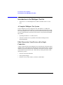


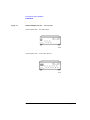

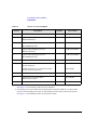
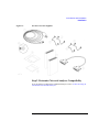
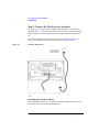

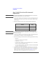
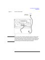
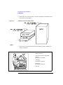
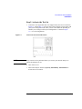


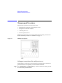


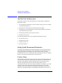
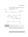


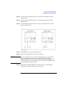
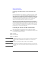


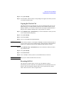


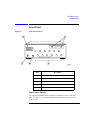


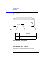


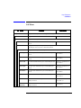

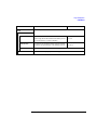
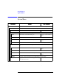


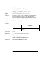


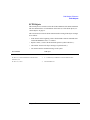


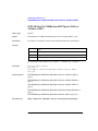
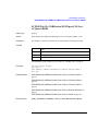

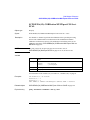


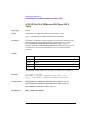
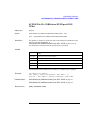
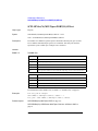


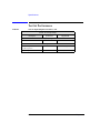
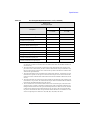

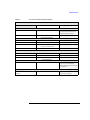
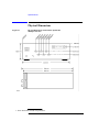


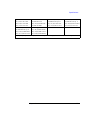


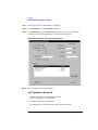


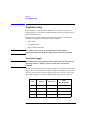


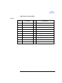
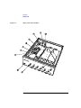
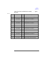
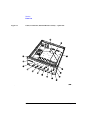

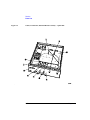

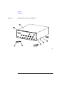
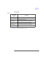


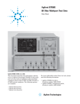
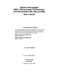


![SPARK Examiner User Manual – Release 7.3 [NT]](http://vs1.manualzilla.com/store/data/006881620_1-d7cb5afdd9ed8db40217375e4b5222ba-150x150.png)