1
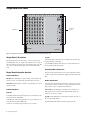
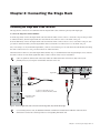
Stage Rack
Installation Guide
Digidesign
2001 Junipero Serra Boulevard
Daly City, CA 94014-3886 USA
tel: 650·731·6300
fax: 650·731·6399
Technical Support (USA)
tel: 650·731·6100
fax: 650·731·6384
Product Information (USA)
tel: 650·731·6102
tel: 800·333·2137
International Offices
Visit the Digidesign Web site
for contact information
Web Site
www.digidesign.com
Copyright
This guide is copyrighted ©2005 by Digidesign, a division of Avid Technology, Inc.
(hereafter “Digidesign”), with all rights reserved. Under copyright laws, this guide
may not be duplicated in whole or in part without the written consent of
Digidesign.
DIGIDESIGN, AVID, D-SHOW, and PRO TOOLS are trademarks or registered
trademarks of Digidesign and/or Avid Technology, Inc. All other trademarks are
the property of their respective owners.
Product features, specifications, system requirements, and availability are
subject to change without notice.
PN 9327-11996-00 REV A 02/05
Important Safety Instructions
1) Read these instructions.
2) Keep these instructions.
3) Heed all warnings.
4) Follow all instructions.
5) Do not use this apparatus near water.
6) Clean only with dry cloth.
Communications & Safety Regulation Information
Compliance Statement
The models D-Show Main, D-Show Sidecar, D-Show FOH Rack, and D-Show Stage
Rack comply with the following standards regulating emissions and immunity:
• FCC Part 15 Class B
• EN55103 – 1, environment E3
• EN55103 – 2, environment E3
• AS/NZS 3548 Class B
• CISPR 22 Class B
• ICES-003 Class B
Canadian Compliance Statement:
This Class B digital apparatus complies with Canadian ICES-003
Cet appareil numérique de la classe B est conforme à la norme NMB-003 du
Canada.
CE Compliance Statement:
7) Do not block any ventilation openings. Install in accordance with the
manufacturer’s instructions.
8) Do not install near any heat sources such as radiators, heat registers, stoves,
or other apparatus (including amplifiers) that produce heat.
9) Do not defeat the safety purpose of the polarized or grounding-type plug. A
polarized plug has two blades with one wider than the other. A grounding type
plug has two blades and a third grounding prong. The wide blade or the third
prong are provided for your safety. If the provided plug does not fit into your
outlet, consult an electrician for replacement of the obsolete outlet.
10) Protect the power cord from being walked on or pinched particularly at plugs,
convenience receptacles, and the point where they exit from the apparatus.
11) Only use attachments/accessories specified by the manufacturer.
12) Use caution when replacing the Lithium battery in the FOH Rack unit. There
is danger of explosion if battery is incorrectly replaced. Replace only with the
same or equivalent type.
13) Unplug this apparatus during lightning storms or when unused for long
periods of time.
Digidesign is authorized to apply the CE (Conformité Europénne) mark on this
compliant equipment thereby declaring conformity to EMC Directive
89/336/EEC and Low Voltage Directive 73/23/EEC.
Australian Compliance:
Radio and Television Interference
This equipment has been tested and found to comply with the limits for a Class B
digital device, pursuant to Part 15 of the FCC Rules.
Communications Statement
This equipment has been tested to comply with the limits for a Class B digital
device. Changes or modifications to this product not authorized by Digidesign,
Inc., could void the Certification and negate your authority to operate the product.
This product was tested for CISPR compliance under conditions that included the
use of peripheral devices and shielded cables and connectors between system
components. Digidesign recommends the use of shielded cables and connectors
between system components to reduce the possibility of causing interference to
radios, television sets, and other electronic devices.
Safety Statement
This equipment has been tested to comply with USA and Canadian safety
certification in accordance with the specifications of UL Standards: UL60065 7th
/IEC 60065 7th and Canadian CAN/CSA C22.2 60065:03. Digidesign Inc., has
been authorized to apply the appropriate UL & CUL mark on its compliant
equipment.
Warning
14) Refer all servicing to qualified service personnel. Servicing is required when
the apparatus has been damaged in any way, such as power-supply cord or plug
is damaged, liquid has been spilled or objects have fallen into the apparatus, the
apparatus has been exposed to rain or moisture, does not operate normally, or
has been dropped.
Contents
Chapter 1. Stage Rack Overview . . . . . . . . . . . . . . . . . . . . . . . . . . . . . . . . . . . . . . . . . . . . . . . . . . . . . . . . . . . . . . . . . . . 1
Stage Rack Features . . . . . . . . . . . . . . . . . . . . . . . . . . . . . . . . . . . . . . . . . . . . . . . . . . . . . . . . . . . . . . . . . . . . . . . . . . . 1
Components . . . . . . . . . . . . . . . . . . . . . . . . . . . . . . . . . . . . . . . . . . . . . . . . . . . . . . . . . . . . . . . . . . . . . . . . . . . . . . . . . 1
Expansion Options . . . . . . . . . . . . . . . . . . . . . . . . . . . . . . . . . . . . . . . . . . . . . . . . . . . . . . . . . . . . . . . . . . . . . . . . . . . . . 1
Operational Requirements . . . . . . . . . . . . . . . . . . . . . . . . . . . . . . . . . . . . . . . . . . . . . . . . . . . . . . . . . . . . . . . . . . . . . . . 1
Stage Rack Front Panel . . . . . . . . . . . . . . . . . . . . . . . . . . . . . . . . . . . . . . . . . . . . . . . . . . . . . . . . . . . . . . . . . . . . . . . . . 2
Stage Rack Back Panel . . . . . . . . . . . . . . . . . . . . . . . . . . . . . . . . . . . . . . . . . . . . . . . . . . . . . . . . . . . . . . . . . . . . . . . . . 3
Chapter 2. Connecting the Stage Rack . . . . . . . . . . . . . . . . . . . . . . . . . . . . . . . . . . . . . . . . . . . . . . . . . . . . . . . . . . . . . 5
Connecting the Stage Rack to the FOH Rack . . . . . . . . . . . . . . . . . . . . . . . . . . . . . . . . . . . . . . . . . . . . . . . . . . . . . . . . . . 5
Audio Connections . . . . . . . . . . . . . . . . . . . . . . . . . . . . . . . . . . . . . . . . . . . . . . . . . . . . . . . . . . . . . . . . . . . . . . . . . . . . 6
Contents iii
iv Stage Rack Guide
Chapter 1: Stage Rack Overview
Stage Rack Features
The Stage Rack provides the primary audio connections to the
Digidesign VENUE system, handling mic/line source input,
and output to monitors and the main speaker system.
The Stage Rack has a flexible I/O scheme that offers the following capacity:
• Up to 48 inputs with remotely controllable mic preamps
and individually selectable Phantom Power
• Up to 48 outputs
Redundant Digital Snake An optional redundant Digital Snake
cable can be run between the FOH Rack and the Stage Rack.
This redundant Snake automatically takes over communication if the first Snake cable fails.
Operational Requirements
Temperature and Ventilation
The Stage Rack unit should be operated away from heat
sources and with adequate ventilation.
Components
Storage
Included Components
The Stage Rack unit should be stored and transported at temperatures not lower than 0 degrees F (–18 degrees C) and not
exceeding 140 degrees F (60 degrees C).
The following components are included in a base Stage Rack
configuration:
• Stage Rack unit with 6 SRI (Stage Rack Input) cards and
1 SRO (Stage Rack Output) card
• AC power cord
Additional Required Components
Operation
The Stage Rack unit should be operated at temperatures not
lower than 40 degrees F (4 degrees C) and not exceeding
115 degrees F (46 degrees C).
Water and Moisture
The following component must be purchased separately:
• Digital Snake cable: this cable can be purchased directly
from Digidesign or assembled by your preferred vendor
using the following cable recommendations.
• Connector (x4): BNC male
The Stage Rack unit should be operated away from sources of
direct moisture and should be kept clear of liquids that might
spill into the units. If condensation is present on the unit,
leave the unit to dry in ambient air for at least one hour before
powering the unit on.
• Cable Type: Coaxial, 75 ohm
• Max Length: 250 ft (76 m) Belden 1885A or
500 ft (152 m) Belden 1694A
Expansion Options
Expanded Stage Rack I/O Each Stage Rack can be expanded
with up to a total of 6 input cards and 6 output cards, for a total of up to 48 inputs or up to 48 outputs.
Additional Stage Rack A second Stage Rack can be added to a
D-Show system, for a total of up to 96 inputs or up to 96 outputs. (A second Stage Rack requires an additional Digital
Snake card be installed in the FOH Rack.)
Cleaning and Maintenance
If you need to clean the surface of the Stage Rack unit, use a
dry cloth. Do not apply any cleaning solutions, spray cleaners,
or abrasives to the surface.
Power Connections
Each power supply in the Stage Rack requires its own power
connection. Each power supply is auto voltage-selecting
(100V to 240V). A modular IEC power cable is provided for
each power supply in the unit.
Chapter 1: Stage Rack Overview 1
Stage Rack Front Panel
Controller
Section
I/O Section
SRI
A
SRI
B
SRI
C
SRI
D
SRI
E
SRI
F
SRO
G
H
J
K
L
M
STAGE
Figure 1. Stage Rack front panel showing 6 SRI (input) cards and an SRO (output) card
Stage Rack I/O Section
The Stage Rack I/O section consists of 12 slots that accept
modular input cards or output cards. The first 6 slots (A–F) of
the Stage Rack accept input cards (such as SRI cards) only. The
last 6 slots (G–M) accept output cards (such as SRO cards)
only.
PQ LED
◆ Flashing means that messages are being received from the
PQ Rack and PQ Controllers.
◆ No flashing indicates that there is no active link between
the PQ Rack and the Stage Rack.
Personal Q Rack Connector
Stage Rack Controller Section
Power Indicators
The Personal Q Rack Connector is a special 4-pin XLR connector that accepts the PQ Link cable supplied with the PQ Rack
unit.
OK LED Green LED lights to indicate that power and fan signals for at least one Stage Rack are functioning correctly.
Snake Connectors
Fault LED Red LED lights to indicate a potential power or fan
signal problem.
The Stage Rack Digital Snake connectors consist of two pairs
of BNC-style connectors (Snake 1 In and Out, Snake 2 In and
Out), and two pairs of signal status indicators.
Comm Indicators
Active LED Green LED lights to indicate that connection to
FOH Rack is active for the corresponding Snake. Only one
Snake can be active at a time.
FOH LED
Flashing fast means Stage Rack processor is OK and is receiving data from the FOH Rack.
◆
Flashing slow means Stage Rack processor is OK but is not
receiving data from the FOH Rack.
Sig LED Green LED lights to indicate that signal is present on
the corresponding Snake.
◆
◆
Full on or off means Stage Rack processor is stuck.
2 Stage Rack Guide
All Snake LEDs flash when no Snake signal is present.
Stage Rack Back Panel
STAGE
DO NOT OBSTRUCT FANS
Power switch
Power connector
Figure 2. Stage Rack back panel
Power Switch
The Power switch applies power to the Stage Rack.
AC Power Connector
The AC Power connector accepts a standard AC power cable.
Stage Rack power supplies are auto-power selecting (100V to
240V) and automatically work with a standard modular power
cord when connected to an AC receptacle in any country.
Chapter 1: Stage Rack Overview 3
4 Stage Rack Guide
Chapter 2: Connecting the Stage Rack
Connecting the Stage Rack to the FOH Rack
The Stage Rack is connected to the FOH Rack with the Digital Snake cable (available separately from Digidesign).
To connect the Stage Rack and the FOH Rack:
1 On the Stage Rack, connect the Digital Snake cable lead with the white connector sleeve to the Snake 1 In port (this port label
is outlined in white), and the Digital Snake cable lead with the red connector sleeve to the Snake 1 Out port.
2 On the FOH Rack, connect the Digital Snake cable lead with the white connector sleeve to the to the Snake 1 Out port (this
port label is outlined in white), and the Digital Snake cable lead with the red connector sleeve to the Snake 1 In port.
3 If you are using a second, redundant Digital Snake, connect it to the Snake 2 ports on each unit in the same manner, matching
the white connector sleeves to the ports whose labels are outlined in white.
When the units are turned on, the Snake Signal LEDs (marked “Sig”) on the FOH Rack and the Stage Rack light solid to indicate
the Snake connection. If the Snake Signal LEDs flash, a Snake connection has not been established.
If there are problems with the Snake connection, double check that all the BNC connectors are fully secured. If the
problem persists, try reversing the red and white connectors on one end.
SNAKE
Signal LED
Active
Sig
Active
Sig
Signal LED
Redundant Snake
connects here
Connectors with white sleeves
attach to terminals with white labels
Redundant Snake
connects here
Figure 3. Detail of Digital Snake cable connection between Stage Rack (left) and FOH Rack (right)
If a second Stage Rack is used, an additional FOH Snake Card must be installed in the FOH Rack. Follow the above
instructions to connect the second Stage Rack to its corresponding FOH Snake card.
Chapter 2: Connecting the Stage Rack 5
Audio Connections
Stage Rack Input Cards
Stage Rack Output Card
SRI
SRI
A
B
SRI
C
SRI
D
SRI
E
SRI
F
SRO
G
H
J
K
L
M
STAGE
Figure 4. Audio connectors on Stage Rack
Audio Inputs
Audio Outputs
(Balanced Female XLR Connectors)
(Balanced Male XLR Connectors)
Connect analog mic-level or line-level input sources to any
of the input connectors on any SRI Card.
◆ Connect analog line-level output destinations (such as
power amplifiers, crossovers, or speakers) to any of the output
connectors on any SRO Card.
◆
Applying Phantom Power to Stage Rack Inputs
Each SRI Card input has available standard 48V phantom
power.
Before connecting or disconnecting a microphone on any
Stage Rack Input, make sure phantom power is turned off
for that input, and the channel is muted.
To apply phantom power to a Stage Rack input source:
1 Target a channel in the ACS section of the control surface.
2 Press the +48V switch in the ACS Input section.
The corresponding channel’s “+48V” LED on the Stage Rack
Input Card lights to indicate phantom power is on.
6 Stage Rack Guide