1
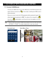
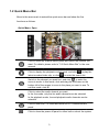
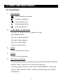
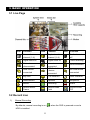
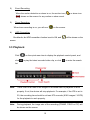
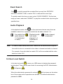
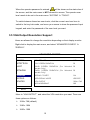
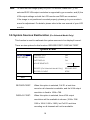
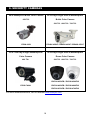
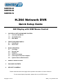
SHDVR-04 SHDVR-08 SHDVR-16 H.264 Network DVR Quick Setup Guide GUI Display with USB Mouse Control 1. GUI DISPLAY WITH USB MOUSE CONTROL 1.1 Connect USB Mouse 1.2 Quick Menu Bar 1.3 Main Menu 2. FRONT AND REAR PANELS 2.1 Front Panel 2.2 Rear Panel 3. BASIC OPERATION 3.1 Live Page 3.2 Record Icon 3.3 Playback 3.4 User Level Switch 3.5 VGA Output Resolution Support 3.6 System Sources Reallocation 4. REMOTE SURVEILLANCE 5. PACKAGE CONTENTS 6. SECURITY CAMERAS Please read instructions thoroughly before operation and retain it for future reference. For the actual display & operation, please refer to your DVR in hand. Copyright © 2011 QSG_V1.2_R201201-V05 1. GUI DISPLAY WITH USB MOUSE CONTROL 1.1 Connect USB Mouse Connect your USB mouse to one of the USB ports on the DVR front panel, and check if there’s a mouse icon ( ) on the screen, indicating the USB mouse is detected properly. Move your mouse to enter the DVR password with the password keypad. The default administrator password is 0000. The status will be changed from (key lock) to (administrator), and the quick menu bar appears on the left side of the screen. Note: There are two user levels for DVR access which can be set in the main menu “SYSTEM” “TOOLS”. For details, please refer to your user manual. Password Input Quick Menu: Close 2 1.2 Quick Menu Bar Move to the arrow mark to extend the quick menu bar and show the five functions as follows: Quick Menu: Open Click to show the channel switch panel and select the channel you want. For details, please refer to “3.2 Quick Menu Bar” in the user manual. Click to display the playback control panel, and click latest recorded video clip, or click to play the to enter the search list. Switch to the channel you want first, and click to enter the zoom-in mode. In this mode, click and drag the red frame on the bottom left of the screen to move to the place you want to see. To exit this mode, click . Click to select the audio channel you want: In the live mode, only the live audio channels can be selected. In the playback mode, live and playback audio channels can be selected. Click to enter the PTZ mode and show the PTZ camera control panel. Click to show the power off panel to either halt or reboot the system. 3 1.3 Main Menu Right-click anywhere on the screen to show the main menu as follows, and right-click again to exit. Main Menu QUICK START Click to set the status display, image settings, and date & time. DATE SETUP Click to set the date display and daylight saving. SYSTEM Click to set the system configurations. EVENT INFORMATION Click to enter the event search menu. ADVANCED CONFIG Click to set CAMERA, DETECTION, ALERT, NETWORK, DISPLAY, RECORD and DEVICES. SCHEDULE SETTING Click to set record timer, detection timer, and alarm timer. 4 Main Menu Structure QUICK START GENERAL TIME SETUP DATE SETUP DATE INFO DAYLIGHT SYSTEM TOOLS SYSTEM INFO CHANNEL TITLE EVENT STATUS DATE DISPLAY MOUSE SENSITIVITY PRIORITY (For Selected Model Only) RECORD CONFIG DATE TIME DISPLAY DATE OF MODE FORMAT DAYLIGHT SAVING LANGUAGE ADMIN PASSWORD OPERATOR PASSWORD UPGRADE BACKUP CONFIG RESTORE CONFIG BAUD RATE HOST ID R.E.T.R. (For Selected Models Only) AUTO KEY LOCK CLEAR HDD RESET DEFAULT REMOTE CONTROL ID SERIAL TYPE VIDEO FORMAT VERSION BACKUP DATA (USB) BACKUP DATA (DVD) (For Selected Models Only) BACKUP LOG (USB) EVENT INFORMATION QUICK SEARCH EVENT SEARCH HDD INFO EVENT LOG ADVANCED CONFIG CAMERA 5 BRIGHTNESS CONTRAST SATURATION HUE COV. REC CHANNEL TITLE DETECTION ALERT NETWORK ADVANCED CONFIG DISPLAY RECORD DEVICES (For Selected Models Only) SCHEDULE SETTING RECORD DETECTION ALARM 6 LS SS TS MOTION ALARM AREA EXT. ALERT INT. BUZZER KEY BUZZER VLOSS BUZZER MOTION BUZZER ALARM BUZZER HDD BUZZER ALARM DURATION (SEC) HDD NEARLY FULL (GB) NETWORK SNTP FTP E-MAIL DDNS DE-INTERLACE (For Selected Models Only) FULL SCREEN DURATION QUAD SCREEN DURATION (For Selected Models Only) DWELL SCREEN DURATION (For Selected Models Only) DISPLAY COVERT HDD DISPLAY MODE VGA OUTPUT ALPHA BLENDING RECORD CONFIG MANUAL RECORD EVENT RECORD TIMER RECORD PRE-ALARM RECORD (For Selected Models Only) OVERWRITE EVENT RECORD ALL CH KEEP DATA LIMIT (DAYS) RECORD CONFIG 2. FRONT AND REAR PANELS 2.1 Front Panel 1) LED Indicators HDD is reading or recording. An alarm is triggered. Timer recording is on. Under playback status. DVR is powered on. 2) (▲) / (▼) / (◄) / (►) Press ▲ / ▼ / ◄ / ► to move up / down / left / right. In the playback mode: Press “” to pause playback. Press “” to stop playback. Press ““ to fast forward. Press ““ to fast rewind. 3) MENU Press to enter the main menu. 4) ENTER Press to confirm the setting. 5) LIST (Event List Search) Press to quickly search the recorded files by event lists: RECORD / MOTION / ALARM / TIME, or select FULL to show all the event logs. To quickly search the time you want, select “QUICK SEARCH”. Set the time range you want, and select “Start” to play the recorded video clip during the specified time. 7 6) PLAY Press to playback the latest recorded data. 7) SLOW In the playback mode, press to show slow playback. 8) ZOOM Press to enlarge the picture of selected channel in the FRAME or FIELD recording mode. 9) SEQ Press to display each channel in full screen one by one starting from CH1. When the last channel is displayed, it will repeat from CH1 again. To exit this mode, press “SEQ” again. 10) Press to show the 4 channel display mode. 11) CH1 ~ 16 / 1 ~ 8 / 1 ~ 4 Press the channel number buttons to select the channel to display. 12) SEARCH (For Selected Models Only) Press to enter the time search menu. Set the time range you want, and select “START” to play the recorded video clip during the specified time. 13) AUDIO (SLOW + ZOOM) Press “SLOW” + “ZOOM” to select live or playback audio from audio channel 1~4. Live audio from audio channel 1~4 (indicated in white) Playback audio from audio channel 1~4 (indicated in yellow) Audio channel unselected 14) P.T.Z. ( + SEQ) Press “ ” + “SEQ” at the same time to enter / exit the PTZ control mode. 8 15) USB port There are two USB ports on the front panel, one for connecting your USB mouse for mouse control, and the other one for connecting your USB flash drive for video backup. Note: It’s not allowed to have two USB mice or two USB flash drives connected on the front panel. For the compatible USB flash drive list, please refer to “APPENDIX 3” in the user manual. 16) (For Selected Models Only) Press “ ” to open / close the DVD Writer. 2.2 Rear Panel 1) 75Ω / HI-IMPEDANCE (For Selected Models Only) When using Loop function, please switch to HI-IMPEDANCE. When you don’t use Loop function, please switch to 75Ω. 2) VIDEO IN (1 ~ 16 / 1 ~ 8 / 1 ~ 4): Connect to the video connector of a camera. VIDEO LOOP (1 ~ 16 / 1 ~ 8 / 1 ~ 4): Video output connector. (For Selected Models Only) Note: The DVR will automatically detect the video system of the camera, please make sure that the cameras are properly connected to the DVR and power-supplied before the DVR is turned on. 3) AUDIO IN (1~4) Connect to the audio connector of a camera if the camera supports audio recording. Note: To make a video backup with audio, make sure the camera which supports the audio function is connected to the video-in channel and audio-in channel. 9 For example, the audio data from audio CH1 will be recorded with the video data from video CH1. 4) AUDIO OUT Connect to a speaker with 1 mono audio output. Note: To know how many audio outputs your DVR supports, please refer to its specifications. 5) MONITOR Connect to a CRT monitor for video output. 6) CALL (For Selected Models Only) Connect to a monitor specific for sequence display. 7) VGA Connect to a LCD monitor directly. 8) IR (For Selected Models Only) Connect the optional IR receiver extension cable for remote control. 9) EXTERNAL I/O This port is used to connect external devices (such as speed dome cameras or external alarm, etc). For detailed I/O port PIN configuration, please refer to “APPENDIX 6” in your user manual. 10) LAN Connect to Internet by LAN cable. 11) DC 19V Connect to the supplied adapter. 12) Power Switch Switch to “” to turn on the power, and “” to turn off the power. 10 3. BASIC OPERATION 3.1 Live Page Icon Function Icon Function Icon Function Live audio channel (1~4) Playback audio channel (1~4) Audio channel off Digital zoom on Digital zoom off Timer recording Network disconnected Internet connected USB flash drive / device connected USB mouse connected LAN connected No USB device connected Key lock PTZ mode on HDD overwrite Administrator Operator Sequence Motion Recording Alarm Record mode: Frame Record mode: Field Record mode: CIF 3.2 Record Icon 1) Manual Recording By defaults, manual recording is on ( HDD is installed. 11 ) when the DVR is powered on and a 2) Event Recording When the motion detection or alarm is on, the motion icon ( ( 3) ) or alarm icon ) shows on the screen for any motion or alarm event. Timer Recording When timer recording is on, you will see “ 4) ” on the screen. HDD Overwritten Be defaults, the HDD overwritten function is set to ON, and “ ” will be shown on the screen. 3.3 Playback Click “ click ” on the quick menu bar to display the playback control panel, and to play the latest recorded video clip, or click to enter the search list. Note: There must be at least 8192 images of recorded data for playback to work properly. If not, the device will stop playback. For example, if the IPS is set to 30, the recording time should be at least 273 seconds (8192 images / 30 IPS) for the playback to work properly. Note: During playback, the image size of the recording (FRAME, FIELD or CIF) will be shown on the screen. 12 Playback Control Fast Increase the speed for fast forward. Click Forward once to get 4X speed forward and click twice to get 8X speed, etc., and the maximum speed is 32X. Fast Rewind Increase the speed for fast rewind. Click once to get 4X speed rewind and click twice to get 8X speed, etc., and the maximum speed is 32X. / Play / Pause Click to play the latest recorded video clip immediately, and click again to pause. In the pause mode, click once to get one frame forward, and click to get one frame rewind. / Stop Click to stop the video playback. Slow Click once to get 1/4X speed playback, and Playback click twice to get 1/8X speed playback. Previous / Click to jump to the next / previous time Next Hour interval in an hour, for example, 11:00 ~ 12:00 or 14:00 ~ 15:00, and start playing the earliest event video clip recorded during this whole hour. Click to set point A and point B in a video clip, Repeat and the system will play only the specified range in that clip. Click to open the backup menu for video Backup backup. 13 Event Search Click to quickly search the recorded files by event lists: RECORD / MOTION / ALARM / TIME, or select FULL to show all the event logs. To quickly search the time you want, select “QUICK SEARCH”. Set the time range you want, and select “SUBMIT” to play the recorded video clip during the specified time. Audio Playback In the playback mode, click on the quick menu bar as many times as needed to select live or playback audio from the audio channel 1~4. Live audio from audio channel 1~4 (indicated in white). Note: Playback audio from audio channel 1~4 (indicated in yellow). Audio channel unselected To make a video backup with audio, make sure the camera which supports the audio function is connected to the video-in channel and audio-in channel. For example, the audio data from audio CH1 will be recorded with the video data from video CH1. 3.4 User Level Switch In the key lock mode ( ), move your USB mouse to display the password input keypad. There are two user levels for accessing the DVR: Administrator ( ) & Operator ( ). When the administrator password is entered, will be shown on the status bar of the screen and all operations are allowed. The default administrator password is 0000. 14 When the operator password is entered, will be shown on the status bar of the screen, and the main menu is NOT allowed to access. The operator user level needs to be set in the main menu “SYSTEM” “TOOLS”. To switch between these two user levels, click the current user level icon to switch to the key lock mode, and move your mouse to show the password input keypad, and enter the password of the user level you want. 3.5 VGA Output Resolution Support Users are allowed to change the resolution depending on their display monitor. Right-click to display the main menu, and select “ADVANCED CONFIG” “DISPLAY”. ADVANCED CONFIG CAMERA DE-INTERLACE OFF DETECTION FULL SCREEN DURATION 03 ALERT QUAD SCREEN DURATION Models Only) NETWORK DWELL SCREEN DURATION (For Selected 03 Models Only) DISPLAY DISPLAY COVERT ON RECORD HDD DISPLAY MODE HDD SIZE DEVICES VGA OUTPUT 1024 x 768 ALPHA BLENDING 200 (For Selected 03 EXIT Move to “VGA OUTPUT”, and select the VGA resolution you want. There are three options as follows: 1024 x 768 (default) 1280 x 1024 1600 x 1200 15 Note: To have the best image quality on your LCD monitor, make sure (1) the selected DVR VGA output resolution is supported by your monitor, and (2) the VGA output settings on both the LCD monitor and DVR are consistent. If the image is not positioned or scaled properly, please go to your monitor’s menu for adjustment. For details, please refer to the user manual of your LCD monitor. 3.6 System Sources Reallocation (For Selected Model Only) This function is used to reallocate the system sources to live display & record. There are two options for this function: RECORD FIRST / DISPLAY FIRST. QUICK START GENERAL CHANNEL TITLE ON TIME SETUP EVENT STATUS ON DATE DISPLAY ON MOUSE SENSITIVITY -׀׀׀׀׀׀׀׀׀+ PRIORITY (For Selected Model Only) RECORD FIRST RECORD CONFIG SETUP EXIT RECORD FIRST: When this option is selected, Full D1 at real-time record on all channels is available, and the VGA output resolution is fixed to 1024 x 768. DISPLAY FIRST: When this option is selected, three VGA output resolutions will be available to choose (1024 x 768 / 1280 x 1024 / 1600 x 1200), but Full D1 real-time recording on all channels will not be available. 16 4. REMOTE SURVEILLANCE Remote access via different platforms is widely supported: A) ® ® ® For mobile platforms, iPhone , AndroidTM, Windows Mobile & BlackBerry are available with the free program, EagleEyes, installed. B) ® ® ® For web browsers, Internet Explorer , Mozilla Firefox , Safari , Google ChromeTM & Opera are supported. ® C) Apple’s media player, QuickTime , is also another supported tool. To monitor and control multiple network devices, you can also install our free CMS software provided within the CD manual. 17 5. PACKAGE CONTENTS SHDVR-04 / SHDVR-08 / SHDVR-16 One (1) 4CH DVR or SHDVR-08 or SHDVR-16 One (1) Remote Control (batteries included) One (1) Remote Control User Manual One (1) Power Adapter with Power Cord Four (4) HDD Screws One (1) User Manual & Software CD One (1) Quick Setup Guide 18 6. SECURITY CAMERAS 24 IR Waterproof Bullet Color Camera 42 IR Day & Night Effio-E Weatherproof 650 TVL Bullet Color Camera 500 TVL / 600 TVL / 700 TVL EIR24-3650 EIR42X-450VF / EIR42X-460VF / EIR42X-470VF 35 IR True Day & Night Weatherproof 36 IR Day & Night Effio-E Weatherproof Color Camera Dome Color Camera 480 TVL 500 TVL / 600 TVL / 700 TVL EIVD36-450VFB / EIVD36-450VFW EIR35-F4840 EIVD36-460VFB / EIVD36-460VFW EIVD36-470VFB / EIVD36-470VFW For more camera selections, visit our website www.sentryus.com. 19