1
Note: The Parking Light Output Relay of the
unit gives two clicking sounds for each flash
of the lights: one click when the lights would
go ON and one click when the lights would
go OFF.)
♦ Parking Light flashes to which the text
refers throughout this manual refer to the
Parking Light output of the unit, not of the
vehicle.
Harness Description
When connecting a System, it is important to make sure that the connector with the Ground wire is
connected first, before making the 12-volt connections. Should the Unit be powered up before
being grounded, there could be serious damage to internal components of the Unit.
Be careful not to power up a System before it is properly grounded. To avoid any accident, it is
recommended to pull out the Fuses from their sockets before the installation, and to put them back
during the very last steps.
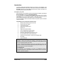
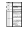
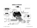
6-Pin Main Ignition Harness
Wire
Colour
Function
A
RED
(+) 12 V Battery
B
PURPLE
(+) Starter output
(30 A)
C
RED
(+) 12 V Battery
D
YELLOW
(+) Ignition
output (30 A)
E
ORANGE
(+) Accessories
output (30 A)
F
GREEN
(+) Fifth Relay
output (30 A)
Description
Connect to the largest 12 V supply wire at the Ignition Harness.
Ensure that the OEM power wire is fused for more than 30 A.
Connect to the Starter wire of the vehicle. The source wire should
have +12 V with the Ignition Key in the CRANK position only.
Connect to the largest 12 V supply wire at the Ignition Harness.
Ensure that the OEM power wire is fused for more than 30 A.
Connect to the Ignition wire of the vehicle. The source wire should
have +12 V with the Ignition Key in the IGNITION ON (RUN) and
CRANK positions.
Connect to the Accessories wire of the vehicle. The source wire
must have power with the Ignition Key in the IGNITION ON (RUN)
position only (no power in the CRANK position).
This wire will power the Heater Fan.
This high-current output can be used to power a second Ignition,
Accessories or Crank wire. See Jumper Setting, later in this
Guide, for correct output.
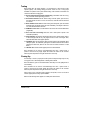
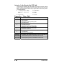
5-pin Secondary Harness
Wire
Colour
1
BLACK
2
PURPLE
3
GREY
4
ORANGE
Installation Guide
Function
Description
This wire must be connected to bare, unpainted metal (the Chassis
(–)
or the true Body ground). It is preferable to use a factory ground
Chassis ground
bolt rather than a self-tapping screw. Screws tend to get loose or
input
rusted over time and can cause erratic problems.
This wire must be connected to the negative side of the Ignition Coil
in vehicles that use conventional coil systems. In Multi-coil systems,
(A.C.)
the Tach wire may be difficult to locate: the negative terminal of an
Tachometer
injector may be used.
input
Note: a Tach-programming procedure must be carried out after the
installation is completed.
Connect this wire to the installed Hood Pin switch supplied. This
(–) Hood Switch
input will disable or shut down the Remote Starter when the Hood is
input
up, and can also set off the Alarm.
This wire must be connected to the Brake Light wire of the vehicle.
(+) Brake Switch This wire must have +12 V only when the Brake Pedal is down.
This input will shut down the Remote Starter if the Brake Pedal is
input
pressed.
P. 5