1
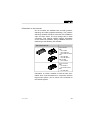
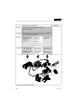
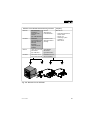
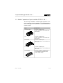
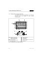
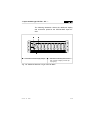
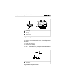
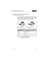
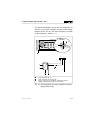
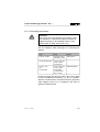
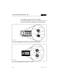
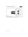
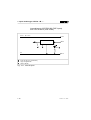
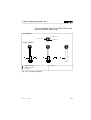
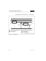
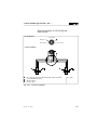
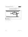
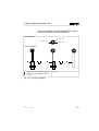
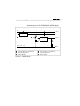
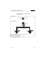
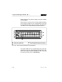
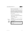
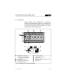
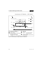
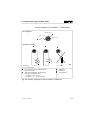
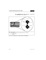
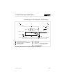
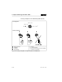
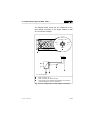
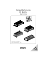
Compact Performance CP Modules Electronics Input modules type CP-E16...-M...-... Output modules type CP-A08...-M12-... Author: Editors: Layout: Typesetting: S. Breuer H.-J. Drung, M. Holder Festo, KI-TD KI-TD Edition: 9909c Printed on 100 % recycled paper © (Festo AG & Co., D-73726 Esslingen, Federal Republic of Germany, 1999) CP..EA 9909c The copying, distribution and utilization of this document as well as the communication of its contents to others without expressed authorization is prohibited. Offenders will be held liable for the payment of damages. All rights reserved, in particular the right to carry out patent, utility model or ornamental design registrations. I Part no. Title: Designation: II 165 225 Manual P.BE-CPEA-GB CP..EA 9909c Contents Designated use. . . . . . . . . . . . . . . . . . . . . . . . . . . . . . . . . . . . . . . . . . . . . IV Target group . . . . . . . . . . . . . . . . . . . . . . . . . . . . . . . . . . . . . . . . . . . . . . . . V Important user instructions . . . . . . . . . . . . . . . . . . . . . . . . . . . . . . . . . . . . . V Information on this manual . . . . . . . . . . . . . . . . . . . . . . . . . . . . . . . . . . . . VII 1. Input module type CP-E16...-M...-... 1.1 1.1.1 1.2 1.3 1.3.1 1.3.2 1.3.3 1.3.4 1.4 1.5 Mode of operation of input modules CP-E16...-M...-... . . . . . . . . 1-3 Display and connecting elements . . . . . . . . . . . . . . . . . . . . . . . . 1-4 Fitting . . . . . . . . . . . . . . . . . . . . . . . . . . . . . . . . . . . . . . . . . . . . . . 1-6 Installation. . . . . . . . . . . . . . . . . . . . . . . . . . . . . . . . . . . . . . . . . . 1-10 Configuring for PNP or NPN mode (type CP-E16-M8-Z only) . . . . . . . . . . . . . . . . . . . . . . . . . . . . . . 1-11 Connecting the separate sensor supply (type CP-E16-M8-Z only) . . . . . . . . . . . . . . . . . . . . . . . . . . . . . . 1-12 Connecting the sensors . . . . . . . . . . . . . . . . . . . . . . . . . . . . . . . 1-15 Connecting the input module . . . . . . . . . . . . . . . . . . . . . . . . . . . 1-26 Instructions on commissioning . . . . . . . . . . . . . . . . . . . . . . . . . . 1-28 Technical data . . . . . . . . . . . . . . . . . . . . . . . . . . . . . . . . . . . . . . 1-33 2. Output module type CP-A08...-M12-... 2.1 2.2 2.3 2.3.1 2.3.2 2.3.3 2.4 2.5 Overview. . . . . . . . . . . . . . . . . . . . . . . . . . . . . . . . . . . . . . . . . . . . 2-3 Fitting . . . . . . . . . . . . . . . . . . . . . . . . . . . . . . . . . . . . . . . . . . . . . . 2-4 Installation. . . . . . . . . . . . . . . . . . . . . . . . . . . . . . . . . . . . . . . . . . . 2-5 Connecting the actuators . . . . . . . . . . . . . . . . . . . . . . . . . . . . . . . 2-6 Connecting the output module . . . . . . . . . . . . . . . . . . . . . . . . . . 2-13 Connecting the load voltage. . . . . . . . . . . . . . . . . . . . . . . . . . . . 2-14 Instructions on commissioning . . . . . . . . . . . . . . . . . . . . . . . . . . 2-17 Technical specifications . . . . . . . . . . . . . . . . . . . . . . . . . . . . . . . 2-20 A. Index CP..EA 9909c III Designated use The CP modules described in this manual have been designed exclusively for use on a CP string, an axis interface string or a CP branch line in conjunction with a CP field bus node, the SPC200 Smart Positioning Controller or the Powerbox type CP-FB-TBOX-SUBD9. CP modules and CP cables may only be used as follows: – as intended for use – in original condition – without unauthorized modifications – in faultless technical condition If used in conjunction with commercially-available components such as sensors and actuators, the specified limit values for pressures, temperatures, electrical data, torques etc. must be observed. Please comply also with national and local safety laws and regulations. All CP modules comply with protection class III. WARNING Use only power units which guarantee reliable isolation of the operating voltages as per IEC 742/ EN 60742/VDE 0551 with at least 4 kV isolation resistance (protected extra low voltage, PELV). Switch power packs are permitted if they guarantee reliable isolation in accordance with EN 60950/ VDE 0805. IV CP..EA 9909c Target group This manual is directed exclusively at technicians who are trained in control and automation technology. Important user instructions Danger categories This manual contains instructions on the possible dangers which may occur if the CP modules are not used correctly. These instructions are always printed in italics, are framed and also signalled by pictograms. A distinction is made between the following: WARNING This means that personal injury or damage to property may occur if these instructions are not observed. CAUTION This means that damage to property may occur if these instructions are not observed. PLEASE NOTE This means that this instruction must also be observed. CP..EA 9909c V Pictograms Pictograms and symbols complement the danger warnings and draw attention to the nature and consequences of dangers. The following pictograms are used: Uncontrolled movements of loose tubing. Unintentional movements of the connected actuators. High voltages or undefined switching states of the electronic components which may influence connected circuits. Electrostatically vulnerable components. These will be damaged if you touch the contact surfaces. Text markings • This mark indicates activities which can be carried out in any order. 1. Figures indicate activites which must be carried out in the numerical order of the figures. – Hyphens indicate general, non-compulsory activities. VI CP..EA 9909c Information on this manual CP I/O modules are available both as PNP (positiveswitching) and NPN (negative-switching). The positiveswitching modules with M12 connection are available in 4-pin and 5-pin forms. The 5-pin design has an earth connection. This manual contains specific information on the method of operation, fitting, installation and commissioning of the following CP modules: This manual refers to: Input modules: PNP - CP-E16-M8 - CP-E16-M12x2 - CP-E16-M12x2-5POL NPN - CP-E16N-M8 - CP-E16N-M12x2 PNP or NPN - CP-E16-M8-Z Output modules: PNP - CP-A08-M12 - CP-A08-M12-5POL NPN - CP-A08N-M12 Information on further modules as well as basic information which must be observed in conjunction with the higher-order system, can be found in the manuals for the relevant system. CP..EA 9909c VII Manuals for the CP system Peripherals Manual "CP system, Installation and commissioning" type P.BE-CPSYS-... Contents General, basic information on operating, fitting, installing and commissioning CP systems. Manual "CP field bus node, programming and diagnosing" type P.BE...-... "CPV valve terminal, CPA valve terminal, pneumatics" type P.BE-CPV-.. or type P.BE-CPA-.. "CP modules, electronics" Contents Special information on commissioning, programming and diagnosing related to the node used. Information on fitting, installing and commissioning CP valve terminals Information on fitting, installing and commissioning CP I/O modules Fig. 0/1: CP system manuals VIII CP..EA 9909c Manuals on the SPC200 Smart Positioning Controller Manuals Manual SPC200 Smart WinPISA type Positioning P.SW-WIN-PISA-... Controller, User manual type P.BE-SPC200-... Contents Installation, commissioning and diagnosis with the SPC200; Standard components and modules Functions of the WinPISA software package Manual "CPV valve terminal, pneumatics" type P.BE-CPV-... "CP modules, electronics" type P.BE-CPEA-... Contents Information on the CPV valve terminals Information on the CP-I/O modules Periphery Manuals on: - proportional directional control valves - service unit - measuring system - cylinders or linear drives Fig. 0/2: Manuals for the SPC200 CP..EA 9909c IX X CP..EA 9909c 1. Input module type CP-E16...-M...-... Chapter 1 Input module type CP-E16...-M...-... CP-E16...-M... 9909c 1-1 1. Input module type CP-E16...-M...-... Contents Input module type CP-E16...-M...-... 1.1 1.1.1 1.2 1.3 1.3.1 1.3.2 1.3.3 1.3.4 1.4 1.5 1-2 Mode of operation of input modules CP-E16...-M...-... . . . . . . . 1-3 Display and connecting elements. . . . . . . . . . . . . . . . . . . . . . . . 1-4 Fitting . . . . . . . . . . . . . . . . . . . . . . . . . . . . . . . . . . . . . . . . . . . . . 1-6 Installation. . . . . . . . . . . . . . . . . . . . . . . . . . . . . . . . . . . . . . . . . 1-10 Configuring for PNP or NPN operation (type CP-E16-M8-Z only) . . . . . . . . . . . . . . . . . . . . . . . . . . . . . 1-11 Connecting the separate sensor supply (type CP-E16-M8-Z only) . . . . . . . . . . . . . . . . . . . . . . . . . . . . . 1-12 Connecting the sensors . . . . . . . . . . . . . . . . . . . . . . . . . . . . . . 1-15 Connecting the input module . . . . . . . . . . . . . . . . . . . . . . . . . . 1-26 Instructions on commissioning . . . . . . . . . . . . . . . . . . . . . . . . . 1-28 Technical data . . . . . . . . . . . . . . . . . . . . . . . . . . . . . . . . . . . . . 1-33 CP-E16...-M... 9909c 1. Input module type CP-E16...-M...-... 1.1 Mode of operation of input modules CP-E16...-M...-... The CP input modules contain digital inputs for connecting sensors, thereby enabling e.g. cylinder positions to be interrogated. A distinction is made between the following types: CP-E16...-M... 9909c Type Explanation CP-E16-M12X2-... Provides 16 PNP inputs; sensor connections via 8 sockets with M12 thread CP-E16N-M12X2 Provides 16 NPN inputs; sensor connections via 8 sockets with M12 thread CP-E16-M8 Provides 16 PNP inputs; sensor connections via 16 sockets with M8 thread CP-E16N-M8 Provides 16 NPN inputs; sensor connections via 16 sockets with M8 thread CP-E16-M8-Z Provides 16 PNP or 16 NPN inputs and a separate connection for the sensor supply voltage 1-3 1. Input module type CP-E16...-M...-... 1.1.1 Display and connecting elements The diagram below shows the display and connecting elements using the example of input module CP-E16-M12x2. 2 1 3 INPUT-N POWER DIAG 6 5 4 7 9 for input type: 1 Designation - INPUT-P for PNP inputs connections 2 Sensor LED for status display 3 Green (one LED per input) - INPUT-N for NPN inputs 8 LED (green) 4 Status connection 5 CP cap 6 Protective for inscription signs (ISB 6x10) 7 Groove connection 8 Earth 9 Type plate Fig. 1/1: Display and connecting elements 1-4 CP-E16...-M... 9909c 1. Input module type CP-E16...-M...-... The following illustration shows the additional display and connection points for the CP-E16-M8-Z input module. 1 2 2 1 Connection for sensor supply voltage LED for indicating short circuit or 2 Red loss of sensor voltage (one LED per input group) Fig. 1/2: Additional features of type CP-E16-M8-Z CP-E16...-M... 9909c 1-5 1. Input module type CP-E16...-M...-... 1.2 Fitting Input modules are intended for fitting onto walls or hat rails. For fitting them onto walls you will require the following surface areas: Fitting on a wall 1-6 Type Surface area CP-E16-M8 Approx. 150 mm x 66 mm CP-E16-M8-Z Approx. 217 mm x 66 mm CP-E16-M12x2-... Approx. 141 mm x 78 mm The diagram below shows the dimensions of the four threaded holes of screw size M4. CP-E16...-M... 9909c 1. Input module type CP-E16...-M...-... 131.9 mm 63 mm 1 2 40 mm 139.9 mm 3 40 mm 207.9 mm module, type CP-E16...-M12x2-... 1 Input module, type CP-E16...-M8 2 Input 3 Input module, type CP-E16-M8-Z Fig. 1/3: Fitting dimensions CP-E16...-M...-... CP-E16...-M... 9909c 1-7 1. Input module type CP-E16...-M...-... PLEASE NOTE For fitting the modules onto a hat rail you will require fastening kit CP-TS-HS35. This kit contains 2 fastenings, 2 M4x12 screws and 2 washers. Fitting onto a hat rail In order to fit the modules onto a hat rail, proceed as follows: 1. Make sure that the fastening surface can support the weight of the module. 2. Fit a hat rail (support rail EN 50022 - 35x15; width 35 mm, height 15 mm). 3. Fasten the hat rail at least every 100 mm to the support surface. 4. Let both fastenings on the hat rail snap into the module (see Fig. 1/4). 5. Screw the housing on to the fastening with the screws supplied as shown in the diagram below. 6. Tighten the screws. The fastening and the housing will then be clamped tight on the hat rail. 1-8 CP-E16...-M... 9909c 1. Input module type CP-E16...-M...-... 1 3 4 5 2 1 2 3 4 5 Fastening Hat rail Housing M4x12 screw Washer Fig. 1/4: Fitting on a hat rail In order to remove the module from a hat rail, proceed as follows: 1. Loosen the screws. 2. Remove the housing. 3. Use a screwdriver to prize open the hat rail and remove the module. 1 1 2 2 Fastening Screwdriver Fig. 1/5: Removing the module CP-E16...-M... 9909c 1-9 1. Input module type CP-E16...-M...-... 1.3 Installation WARNING Before undertaking installation work, switch off the following: - the operating voltage supply and the load voltage supply on the higher-order system (e.g. CP field bus node) - if necessary, the separately supplied voltage supplies. You thereby avoid: – unintentional movements of the connected actuators. – undefined switching states of the electronic components. WARNING Connect the earth cable on the side of the housing (see Fig. 1/1) with low impedance (short cable with large cross-sectional area) to the earth potential. In this way you can avoid interference caused by electromagnetic influences. 1-10 CP-E16...-M... 9909c 1. Input module type CP-E16...-M...-... 1.3.1 Configuring for PNP or NPN operation (type CP-E16-M8-Z only) The CP-E16-M8-Z input module provides PNP or NPN inputs. A bridge must be installed in the sensor supply socket for setting to either PNP or NPN mode. The following illustrations show the rear of the socket. 1 3 2 3 2 2 5 4 1 mode 1 PNP (pins 2 and 3 bridged) 5 4 1 mode 2 NPN (pins 2 and 1 bridged) Pin assignment Pin 1 + 24 V DC ± 25 % Pin 2 PNP/NPN Pin 3 0V Pin 4 NC Pin 5 Earth connection Fig. 1/6: Configuring for PNP or NPN (type CP-E16-M8-Z only) CP-E16...-M... 9909c 1-11 1. Input module type CP-E16...-M...-... 1.3.2 Connecting the separate sensor supply (type CP-E16-M8-Z only) WARNING Use only power units which guarantee reliable isolation of the operating voltages as per IEC 742/ EN 60742/VDE 0551 with at least 4 kV isolation resistance (protected extra low voltage, PELV). Switch power packs are permitted if they guarantee reliable isolation in accordance with EN 60950/ VDE 0805. By using PELV power units, protection against electric shock (protection against direct and indirect contact) in accordance with EN 60204-1/IEC 204 is guaranteed on Festo valve terminals. Safety transformers with the adjacent designation must be used for supplying PELV networks. The CP input modules must be earthed in order to ensure their function (e.g. EMC). The sensors are supplied with DC + 24 V through the sensor supply connection. The module allows sensors having higher current draw to be used (max. 125 mA per sensor). 1-12 CP-E16...-M... 9909c 1. Input module type CP-E16...-M...-... The following illustration shows the pin assignment as well as a connection example for PNP mode (bridge between pins 2 and 3). See also "Configuring for PNP or NPN operation", section 1.3.1. Pin 2: PNP/NPN 1 Pin 5: Pin 3: 0V Pin 4: n.c. Pin 1: 24 V DC ± 25 % 2 2 3 1 4 5 3 1 2 3 Earth connection pin 5 Earth connection on housing side Sensor supply can be individually switched off; supply voltage is provided through the CP connection Fig. 1/7: Pin assignment and wiring example for sensor supply (PNP mode) CP-E16...-M... 9909c 1-13 1. Input module type CP-E16...-M...-... PLEASE NOTE • Always connect earth to pin 5 of the sensor supply. • Make sure the connection between the earth terminal on the left housing side and GND is lowresistance (short lead, large gauge). • Use low-resistance connections to ensure that the module housing and the earth connection on pin 5 are at the same potential and no compensation current flows. In this way you will avoid electromagnetic disturbances. 1-14 CP-E16...-M... 9909c 1. Input module type CP-E16...-M...-... 1.3.3 Connecting the sensors WARNING When using the CP-E16-M8-Z input module, make sure that pin 2 on the sensor supply connection is bridged according to the operating mode of your system (PNP or NPN, see section 1.3.1). Use the following cable and plugs for connecting the sensors. Type Plug Cable CP-E16...-M12x2 SEA-GS-7 (PG7) SEA-WS-7 (PG7) KM12-DUO-... CP-E16-M12x2-5POL Use the plug with union nut with thread M12x1. CP-E16...-M8 and CP-E16-M8-Z Use the plug with union nut with thread M8x1 (outer diameter max. 12 mm). KM8-M8-GSGD-... Fasten the plugs with the aid of the union nuts in order to avoid unintentional loosening e.g. due to vibration. Seal the unused sensor connections with the protective caps supplied. Only then is compliance with class of protection IP65 ensured. CP-E16...-M... 9909c 1-15 1. Input module type CP-E16...-M...-... Pin assignment (inputs PNP and NPN) The following diagrams show the pin assignment of the sensor connections of the different CP input modules. Pin 3: 0 V Pin 1: 24 V 5 7 9 11 13 15 4 6 8 10 12 14 Pin 2: Ex+1 Ex+1 Ex Pin 3: 0 V Pin 2: Ex Pin 1: 24 V E = Input Fig. 1/8: Pin assignment typ CP-E16...-M8 and CP-E16-M8-Z Pin 4: Ex+2 Pin 3: 0 V Pin 1: 24 V Pin 2: Ex+3 Ex+2 Ex Pin 1: 24 V Ex+3 Ex+1 Pin 2: Ex+1 Pin 3: 0 V Pin 4: Ex E = Input Fig. 1/9: Pin assignment type CP-E16...-M12x2 1-16 CP-E16...-M... 9909c 1. Input module type CP-E16...-M...-... Pin 4: Ex+2 1 Pin 3: 0 V Pin 1: 24 V Pin 2: Ex+3 Ex+2 Ex Pin 2: Ex+1 Pin 1: 24 V 1 Ex+3 Ex+1 Pin 3: 0 V Pin 4: Ex E = Input 1 Pin 5: Earth connection Fig. 1/10: Pin assignment type CP-E16-M12x2-5POL CP-E16...-M... 9909c 1-17 1. Input module type CP-E16...-M...-... Internal layout of CP-E16-M8 (PNP inputs) and CP-E16-M8-Z (PNP mode) 24 V + 10/- 15 % Pin 1 Pin 2 1 0V 2 3 Pin 3 Ex (e.g. via field bus) 1 PLC/I-PC recognition Ex 2 Logic 3 Green LED Ex Fig. 1/11: Internal layout 1-18 CP-E16...-M... 9909c 1. Input module type CP-E16...-M...-... Circuitry examples types CP-E16-M8 (PNP inputs) and CP-E16-M8-Z (PNP mode) Pin assignment Pin 3: 0 V Pin 1: 24 V Pin 2: Ex Circuitry examples 1 1 2 3 Three-wire sensor Two-wire sensor Contact 3 2 E = Input Fig. 1/12: Circuitry examples CP-E16...-M... 9909c 1-19 1. Input module type CP-E16...-M...-... Internal layout of CP-E16-M12x2-... (PNP inputs) 24 V + 10/- 15 % Pin 1 7 2 1 Pin 2 3 0V Ex+1 (e.g. via field bus) 1 PLC/I-PC recognition Ex+1 2 Logic 3 Green LED Ex+1 4 5 Pin 4 6 Pin 3 Ex (e.g. via field bus) 4 PLC/I-PC recognition Ex 5 Logic LED Ex 6 Green 5 only with type 7 Pin CP-E16-M12x2-5POL: Earth connection Fig. 1/13: Internal layout 1-20 CP-E16...-M... 9909c 1. Input module type CP-E16...-M...-... Circuitry examples of CP-E16-M12x2-... (PNP inputs) Pin assignment Pin 3: 0 V 1 Pin 2: Ex+1 Pin 1: 24 V Pin 4: Ex Circuitry examples 2 4 1 2 3 4 3 Pin 5 only with type CP-E16-M12x2-5POL: Earth connection 2-way distributor (T-piece) Sensor 2 (Ex+1) Sensor 1 (Ex) E = Input Fig. 1/14: Circuitry examples CP-E16...-M... 9909c 1-21 1. Input module type CP-E16...-M...-... Internal layout of CP-E16N-M8 (NPN inputs) and CP-E16-M8-Z (NPN mode) 0V Pin 3 Pin 2 1 24 V + 10/- 15 % 2 3 Pin 1 Ex (e.g. via field bus) 1 PLC/I-PC recognition Ex 2 Logic 3 Green LED Ex Fig. 1/15: Internal layout 1-22 CP-E16...-M... 9909c 1. Input module type CP-E16...-M...-... Circuitry examples of CP-E16N-M8 (NPN inputs) and CP-E16-M8-Z with NPN operation Pin assignment Pin 3: 0 V Pin 1: 24 V Pin 2: Ex Circuitry examples 1 1 2 3 3 2 Three-wire sensor (negative switching) Two-wire sensor (negative switching) Contact E = Input Fig. 1/16: Circuitry examples CP-E16...-M... 9909c 1-23 1. Input module type CP-E16...-M...-... Internal layout of CP-E16N-M12x2 (NPN inputs) 0V Pin 3 2 1 Pin 2 5 3 4 Pin 4 6 24 V + 10/- 15 % Ex+1 (e.g. via field bus) 1 PLC/I-PC recognition Ex+1 2 Logic 3 Green LED Ex+1 Pin 1 Ex (e.g. via field bus) 4 PLC/I-PC recognition Ex 5 Logic 6 Green LED Ex Fig. 1/17: Internal layout 1-24 CP-E16...-M... 9909c 1. Input module type CP-E16...-M...-... Circuitry examples of CP-E16N-M12x2 (NPN inputs) Pin assignment Pin 3: 0 V Pin 4: Ex Pin 2: Ex+1 Pin 1: 24 V Circuitry examples 1 3 1 2 3 2-way connector (T piece) Sensor 2 (Ex+1) (negative switching) Sensor 1 (Ex) (negative switching) 2 E = Input Fig. 1/18: Circuitry examples CP-E16...-M... 9909c 1-25 1. Input module type CP-E16...-M...-... 1.3.4 Connecting the input module WARNING Please observe the maximum permitted string lengths in each case. You will then avoid faults in data exchange between the input module and the higher-order system (e.g. the field bus node). Use only the following cables for connecting the modules: For connection to Max. permitted string length Cable type Field bus node with CP connection 10 m Axis interface type SPC-AIF-... See manual for SPC200 type P.BE-SPC200-... - KVI-CP-1-... or - KVI-CP-2-... (can be used as drag chain) Powerbox type CP-FB-TBOX-... See manual for higher-order system The following functions are provided for the module through the CP cable: – Supply voltage for the internal electronics – Data exchange connection – For input modules not having a sensor supply connection: Operating voltage for the connected sensors. 1-26 CP-E16...-M... 9909c 1. Input module type CP-E16...-M...-... Input modules can be connected to one of the following: – the CP connection of the higher-order system (field bus node, axis interface or Powerbox) – the CP connection of an output module – the CP connection of a valve terminal Further instructions can be found in the appropriate system manuals. CP-E16...-M... 9909c 1-27 1. Input module type CP-E16...-M...-... 1.4 Instructions on commissioning WARNING Please be careful if you modify the line assignment of your CP system at a later stage. After saving the string assignment or hardware configuration, check the address assignment of your higher-order system before you start user programs. You thereby avoid: – addressing errors if CP modules are incorrectly fitted. With the CP field bus node, the new string assignment must be saved if it has been modified (CP modules added or removed). To do this press the SAVE button on the node. Proceed as described in the manual "CP system, installation and commissioning." With the SPC200, the new hardware configuration must also be saved if the string assignment has been modifed. Proceed here as described in the manual for the SPC200 or for WinPISA. Status LED 1-28 The operating status of the input module is shown by the status LED on the CP connection (see following table). CP-E16...-M... 9909c 1. Input module type CP-E16...-M...-... Status LED Sequence ON Operating status Error treatment Operating voltage applied None - Operating voltage not applied or no connection to higher-order system • Check CP cable and operating voltage connection on higherorder system or OFF LED lights up ON LED is out OFF or In conjunction with CP node: - incorrect string assignment ascertained during operation In conjunction with SPC200: - see user manual for SPC200 ON OFF LED flashes - Test phase after voltage is switched on or - short circuit in sensor supply3) or Type CP-E16-M8-Z: - Sensor supply voltage too low (< 17 V) or In conjunction with CP node: - incorrect string assignment when voltage is switched on In conjunction with the SPC200: - see user manual for SPC200 • Correct string assignment • See user manual type P.BE-SPC200 • None or • Eliminate short circuit and delete error1) or • Eliminate undervoltage • Check string assignment2) • See user manual type P.BE-SPC200 1) For type CP-E16-M8-Z the error is automatically cleared. In other modules the error is cleared by disconnecting the input module from the branch or by resetting the supply voltage on the host system. 2) After changing the branch configuration (adding or removing CP modules) the new branch configuration must be stored by pressing the SAVE button on the node (see "CP System, Installation and Commissioning"). 3) With type CP-E16-M8-Z the short-circuit LED for the appropriate input group lights up. CP-E16...-M... 9909c 1-29 1. Input module type CP-E16...-M...-... Short circuit of the sensor supply on input module CP-E16-M8-Z When there is a short circuit, the input module switches off the supply voltage for the corresponding input group and reports the fault to the host system. The short circuit LED on the corresponding input group lights up. 1 2 3 group 1 (upper row) 1 Input 2 Input group 2 (lower row) LED indicating short circuit or loss of 3 Red sensor voltage (one LED per input group) Fig. 1/19: Short circuit indicators for CP-E16-M8-Z The status LEDs for the corresponding input group are switched off and the corresponding inputs are at 0. The other input group remains operational. After removing the short circuit the error is self-clearing. 1-30 CP-E16...-M... 9909c 1. Input module type CP-E16...-M...-... Short circuit in sensor supply for input modules without sensor supply connection If there is a short circuit, the input module will switch off the power supply to the sensors and lock them in this state. It will also communicate the error to the higherorder system. The status LEDs will be switched off and the inputs of the module will transmit a 0-signal. When the short circuit has been eliminated, you can delete this error as follows: In conjunction with the CP field bus node: • Disconnect the input module briefly from the line, or • switch off the power supply at the node and then switch it on again. In conjunction with the SPC200: • Proceed as described in the user manual type P.BE-SPC200. Replacing the CP module If there is a fault in the CP module during operation, you can replace the module with one of the same type, even during operation. PLEASE NOTE Observe here the instructions in the manual for the higher-order system (e.g. CP system, CP field bus node, SPC200). CP-E16...-M... 9909c 1-31 1. Input module type CP-E16...-M...-... Status display Next to the sensor connections there is/are one or two green LEDs. These indicate the state of the signal at the relevant input. The meanings are as follows: Status LED Sequence ON LED lights up Status 1-signal OFF ON 0-signal OFF LED is out ON OFF LED flashes Only during switch-on phase: - if there is a 1-signal and - if there is a line assignment error. PLEASE NOTE In conjunction with the CP field bus node: If there is a line assignment error during the switchon phase, the CP node will switch the power supply to the input module and also the power supply to the connected sensors on and off cyclically. In this case, the status LEDs and the LEDs of the connected sensors will therefore flash, providing they transmit a 1-signal. 1-32 CP-E16...-M... 9909c 1. Input module type CP-E16...-M...-... 1.5 Technical data Technical data Type CP-E16-M8-Z positive-switching (PNP) or negative-switching (NPN) mode Temperature range: - Operation - Storage/transport - 5 °C... + 50 °C - 20 °C... + 70 °C Relative humidity 95 % non condensing Protection class as per EN 60529; plug connector attached or fitted with cover cap IP65 Shock protection as per EN 60204/IEC 204 (Protection against direct and indirect contact) when connected to a PELV power supply (Protected ExtraLow Voltage) Electromagnetic compatibility - Interference emission - Resistance to interference Tested as per EN 55011 limit class B Tested as per EN 50082-2 Digital inputs - Type 16 inputs as per IEC 1131-2 type 2 inputs 24 V DC positive or negative-switching - Logic level positive-switching ON OFF - Logic level negative-switching ON OFF PNP (referenced to 0 V): 8.6 V 6V NPN (referenced to 24 V): 6V 8.6 V - Current consumption (at 24 V) (input current from sensor to input) For "logic 1" Typ. 8 mA - Response delay (at 24 V) Typ. 3 ms Sensor supply VD 24 V 25 % Max. 1 A per input group (electronic short circuit protection per group) Galvanic isolation None Internal current consumption (electronics) < 40 mA CP-E16...-M... 9909c 1-33 1. Input module type CP-E16...-M...-... Technical data Positive-switching input modules (NPN) without separate sensor supply connection Types CP-E16-M8 and CP-E16-M12x2 Type CP-E16-M12x2-5POL Temperature range: - Operation - Storage/transport - 5 °C... + 50 °C - 20 °C... + 70 °C Relative humidity 95 % non condensing Protection class as per EN 60529; plug connector attached or fitted with cover cap IP65 Shock protection as per EN 60204/IEC 204 (Protection against direct and indirect contact) when connected to a PELV power supply (Protected ExtraLow Voltage) Electromagnetic compatibility - Interference emission Tested to EN 55011 limit class B Tested to EN 50082-2 Tested to EN 55011 limit class B Tested to EN 50082-2 16 inputs as per IEC 1131-2 type 2 inputs 24 V DC positive-switching 16 inputs as per IEC 1131-2 type 2 inputs 24 V DC negative-switching > 11 V <5V ≥ 8.6 V ≤6V - Current consumption (at 24 V) (input current from sensor to input) For "logic 1" Typ. 8 mA For "logic 1" Typ. 6 mA - Response delay (at 24 V) Typ. 5 ms Typ. 3 ms - Resistance to interference Digital inputs - Type - Logic level: ON OFF Sensor supply VD 24 V 25 % Max. 0.5 A (electronic short circuit protection) Galvanic isolation None Internal current consumption (electronics) < 40 mA 1-34 Max. 90 mA CP-E16...-M... 9909c 1. Input module type CP-E16...-M...-... Technical data Negative-switching input modules (NPN) Type CP-E16N-M8 and type CP-E16N-M12x2 Temperature range: - Operation - Storage/transport - 5 °C ... + 50 °C - 20 °C ... + 70 °C Relative humidity 95 % non condensing Protection class as per EN 60 529; plug connector attached or fitted with cover cap IP65 Shock protection as per EN 60204/ IEC 204 (Protection against direct and indirect contact) when connected to a PELV power supply (Protected Extra-Low Voltage) Electromagnetic compatibility - Interference emission - Resistance to interference Digital inputs - Type Tested as per EN 55011 limit value class B Tested as per EN 50082-2 16 inputs as per IEC 1131-2 type 2 inputs 24 V DC negative switching - Logic level: ON OFF < VD -11 V > VD - 5 V - Current consumption (at 24 V) (input current from sensor to input) For "logic 0" Typ. 8 mA - Response delay (at 24 V) Typ. 5 ms Sensor supply VD 24 V 25 % Max. 0.5 A (electronic short circuit protection) Galvanic isolation None Internal current consumption (electronics) Max. 90 mA CP-E16...-M... 9909c 1-35 1. Input module type CP-E16...-M...-... 1-36 CP-E16...-M... 9909c 2. Output module type CP-A08...-M12-... Chapter 2 Output module type CP-A08...-M12-... CP-A08...-M12 9909c 2-1 2. Output module type CP-A08...-M12-... Contents Output module type CP-A08...-M12-... 2.1 2.2 2.3 2.3.1 2.3.2 2.3.3 2.4 2.5 2-2 Overview . . . . . . . . . . . . . . . . . . . . . . . . . . . . . . . . . . . . . . . . . . . 2-3 Fitting . . . . . . . . . . . . . . . . . . . . . . . . . . . . . . . . . . . . . . . . . . . . . 2-4 Installation. . . . . . . . . . . . . . . . . . . . . . . . . . . . . . . . . . . . . . . . . . 2-5 Connecting the actuators . . . . . . . . . . . . . . . . . . . . . . . . . . . . . . 2-6 Connecting the output module . . . . . . . . . . . . . . . . . . . . . . . . . 2-13 Connecting the load voltage. . . . . . . . . . . . . . . . . . . . . . . . . . . 2-14 Instructions on commissioning . . . . . . . . . . . . . . . . . . . . . . . . . 2-17 Technical specifications . . . . . . . . . . . . . . . . . . . . . . . . . . . . . . 2-20 CP-A08...-M12 9909c 2. Output module type CP-A08...-M12-... 2.1 Overview Output module type CP-A08...-M12-... provides 8 universally usuable digital outputs for controlling lowcurrent consuming devices (bulbs, further valves etc). The following diagram shows the display and connecting elements on the output module. 3 2 1 4 OUTPUT-P POWER DIAG 0 6 1 2 3 4 5 7 8 0 9 Designation for output type - OUTPUT-P for PNP outputs - OUTPUT-N for NPN outputs CP connection Connections for actuators Yellow LED for status display (one LED per output) LED (green) 5 Status voltage connection 6 Load cap 7 Protective for inscription signs (IBS 6x10) 8 Recess connection 9 Earth 0 Type plate Fig. 2/1: Display and connecting elements CP-A08...-M12 9909c 2-3 2. Output module type CP-A08...-M12-... 2.2 Fitting The output module is intended for fitting onto a wall or a hat rail. It requires a fitting surface of approximately 173 mm x 78 mm. Fitting on a wall The diagram below shows the dimensions for the four threaded holes for the M4 screws. 63 mm 163.9 mm Fig. 2/2: Fitting dimensions Fitting on a hat rail 2-4 Fitting onto a hat rail is undertaken in exactly the same way as with input modules CP-E16...-M... (see section 1.2). CP-A08...-M12 9909c 2. Output module type CP-A08...-M12-... 2.3 Installation WARNING Before undertaking maintenance work, switch off: • the load voltage supply to the relevant output modules. Also switch off the following before undertaking installation work: • the voltage supply for the higher-order system • the power supply to all the output modules. You thereby avoid: • unintentional movements of the connected actuators. • undefined switching states of the electronic components. WARNING Connect the earth cable on the side of the housing (see Fig. 2/1) with low impedance (short cable with large cross-sectional area) to the earth potential. In this way you can avoid interference caused by electromagnetic influences. CP-A08...-M12 9909c 2-5 2. Output module type CP-A08...-M12-... 2.3.1 Connecting the actuators Use plugs with union nuts with M12 thread for connecting the actuators. Fasten the plugs with the aid of the union nuts in order to avoid unintentional loosening e.g. due to vibration. Seal the unused sensor connections with the protective caps supplied. Only then is compliance with class of protection IP65 ensured. Pin assignment of the actuator connections CP-A08-M12-... (PNP outputs) Pin 4: Ax+1 Pin 3: 0V Pin 1: n.c. Pin 2: n.c. Ax+1 Ax Pin 2: n.c. Pin 1: n.c. Pin 3: 0V Pin 4: Ax n.c. = not connected A = Output Fig. 2/3: Pin assignment of output module CP-A08-M12 2-6 CP-A08...-M12 9909c 2. Output module type CP-A08...-M12-... By means of internal connections, two outputs can be connected to each of the output sockets 0, 2, 4 and 6 on the CP output module type CP-A08-M12-5POL. 1 Pin 4: Ax+1 Pin 1: n.c. Pin 3: 0V Pin 2: n.c. 2 Ax+1 Ax Pin 1: n.c. 1 1 2 Pin 5: Earth connection Internal connection in the module Pin 2: Ax+1 Pin 3: 0V Pin 4: Ax A = Output n.c. = not connected Fig. 2/4: Pin assignment of output module CP-A08-M12-5POL CP-A08...-M12 9909c 2-7 2. Output module type CP-A08...-M12-... Internal layout of CP-A08-M12-... (PNP outputs) 8 1 Pin 2 24 V ± 25 % 4 Pin 1 2 4 4 3 6 Pin 1 Pin 2 Pin 4 Pin 4 Pin 3 0V 7 5 Pin 3 9 voltage connection LED 1 Load 5 Yellow Ax (e.g. via field bus) Green LED 2 PLC/IPC 6 isolation circuit, overload 3 Galvanic 7 Diagnosis •• short type CP-A08-M12: not connected load voltage failure 4 With With type CP-A08-M12-5POL: connection 8 Actuator - connection 0, 2, 4, 6: Ax+1 Pin 5 only with type CP-A08-M12-5POL: 9 - connection 1, 3, 5, 7: not connected Earth connection Fig. 2/5: Internal layout of output module CP-A08-M12-... 2-8 CP-A08...-M12 9909c 2. Output module type CP-A08...-M12-... Circuitry examples of CP-A08-M12-... (PNP outputs) Pin assignment Pin 4: Ax+1 Pin 3: 0 V 2 Examples of circuitry 3 1 Pin 1: n.c. Pin 2: 4 5 24V A = Output n.c. = not connected 1 2 Pin 5 only with type CP-A08-M12-5POL: Earth connection With type CP-A08-M12: not connected With type CP-A08-M12-5POL: - connection 0, 2, 4, 6: Ax+1 - connection 1, 3, 5, 7: not connected 1 3 Example 2 4 Example 5 Not permitted Fig. 2/6: Circuitry examples of output module CP-A08-M12-... CP-A08...-M12 9909c 2-9 2. Output module type CP-A08...-M12-... Pin assignment of the actuator connections CP-A08N-M12 (NPN outputs) Pin 4: Ax+1 Pin 3: n.c. Pin 2: 1 Pin 1: 24 V*) Ax+1 Ax Pin 1: 24 V*) Pin 2: 1 Pin 3: n.c. Pin 4: Ax 1 *) Earth connection Consuming device/load must be supplied via this 24 V connection n.c. = not connected A = Output Fig. 2/7: Pin assignment of output module CP-A08N-M12 2-10 CP-A08...-M12 9909c 2. Output module type CP-A08...-M12-... Internal layout of CP-A08N-M12 (NPN outputs) 1 Pin 3 8 0V 4 3 2 Pin 1 Pin 2 1 2 3 4 Pin 2 6 Pin 4 24 V ± 25 % Load voltage connection PLC/I-PC Ax+1 (e.g. via field bus) Galvanic isolation Not connected Pin 3 Pin 4 7 5 Pin 1 LED 5 Yellow LED 6 Green circuit, overload 7 Diagnosis •• short load voltage failure 8 Actuator connection Fig. 2/8: Internal layout of output module CP-A08N-M12 CP-A08...-M12 9909c 2-11 2. Output module type CP-A08...-M12-... Circuitry examples of CP-A08N-M12 (NPN outputs) Pin assignment Pin 4: Ax+1 Pin 3: n.c. Pin 2: Circuitry examples 2 connection 1 Earth 1 2 Example 2 3 Example 4 Not permitted 1 Pin 1 : 24 V*) 3 4 A = Output n.c. = not connected *) Consuming device/load must be supplied via this 24 V connection Fig. 2/9: Circuitry examples of output module CP-A08N-M12 2-12 CP-A08...-M12 9909c 2. Output module type CP-A08...-M12-... 2.3.2 Connecting the output module WARNING Please observe the maximum permitted string lengths. In this way you will avoid faults in data exchange between the output module and the higherorder system (e.g. field bus node). Use only the following cables to connect the modules. For connection to Max. permitted string length Cable type Field bus node with CP connection 10 m Axis interface type SPC-AIF-... See manual for the SPC200 type P.BE-SPC200-... - KVI-CP-1-... or - KVI-CP-2-... (can be used as drag chain) Powerbox type CP-FB-TBOX-... See manual for the higher-order system Communication takes place via the CP cable and the operating voltage for the internal electronics of the module is also supplied via the CP cable. The output module is connected directly to the CP connection of the higher-order system (field bus node, axis interface or Powerbox). Detailed instructions can be found in the relevant system manual. CP-A08...-M12 9909c 2-13 2. Output module type CP-A08...-M12-... 2.3.3 Connecting the load voltage WARNING Use only power units which guarantee reliable isolation of the operating voltages as per IEC 742/ EN 60742/VDE 0551 with at least 4 kV isolation resistance (protected extra low voltage, PELV). Switch power packs are permitted if they guarantee reliable isolation in accordance with EN 60950/ VDE 0805. By using PELV power units, protection against electric shock (protection against direct and indirect contact) in accordance with EN 60204-1/IEC 204 is guaranteed on Festo valve terminals. Safety transformers with the adjacent designation must be used for supplying PELV networks. The valve terminals must be earthed in order to ensure their function (e.g. EMC). The connected actuators are supplied with + 24 V DC via the load voltage connection on the output module. Use a cable with sufficiently large cross-sectional area for the operating voltage. 2-14 CP-A08...-M12 9909c 2. Output module type CP-A08...-M12-... The diagram below shows the pin assignment of the load voltage connection on the output module as well as a connection example. Pin 2: 24 V DC ± 25 % OUTPUT-P POW ER DIAG Pin 1: n.c. Pin 3: 0V Pin 4: 1 2 3 n.c.= not connected 1 2 3 Earth connection pin 4 Earth connection on side of housing Load voltage can be switched off separately; the operating voltage is supplied via the CP connection Fig. 2/10: Pin assignment of load voltage connection CP-A08...-M12 9909c 2-15 2. Output module type CP-A08...-M12-... PLEASE NOTE • Always connect the earth potential to pin 4 of the load voltage connection. • Connect the earth connection on the left-hand side of the housing with low impedance (short cable with large cross-sectional area) to the earth potential. • By means of low impedance connections, make sure that the housing of the output module and the earth connection at pin 4 have the same potential and that there are no equalizing currents. You can then avoid interference caused by electromagnetic influences. PLEASE NOTE Check your EMERGENCY STOP circuit to see which measures are necessary for placing your machine/system in a safe state in the event of an EMERGENCY STOP (e.g. switching off the operating voltage for the valves and output modules, switching off the compressed air). 2-16 CP-A08...-M12 9909c 2. Output module type CP-A08...-M12-... 2.4 Instructions on commissioning WARNING Please be careful when modifying the string assignment at a later stage. After saving the string assignment/hardware configuration, check the address assignment of your higherorder system before starting user programs. You can then avoid: – addressing modules. errors with incorrectly installed CP With CP field bus nodes, the new string assignment must be saved if it has been modified (CP modules added or removed). To do this press the SAVE button on the node. Proceed here as described in the manual "CP system, installation and commissioning." With the SPC200, the new hardware configuration must also be saved after the string assignment has been modified. Proceed here as described in the manual for the SPC200 or for WinPISA. Status LED CP-A08...-M12 9909c The operating status of the output module is shown by the status LED on the CP connection (see following table): 2-17 2. Output module type CP-A08...-M12-... Status LED LED lights up Sequence Operating status Error treatment ON Operating voltage applied None - Operating voltage not applied or no connection to node • Check CP cable and operating voltage connection on the node (pin 1) or OFF ON OFF LED is out or In conjunction with the CP node - incorrect string assignment during operation In conjunction with the SPC200 - see user manual for the SPC200 ON OFF or In conjunction with the CP node - incorrect string assignment when power supply is switched on In conjunction with the SPC200 - see user manual for the SPC200 LED flashes quickly ON LED flashes slowly - Test phase when power supply is switched on or - short circuit/overload on at least one output module OFF Load voltage failure • correct string assignment • See user manual type P.BE-SPC200-... • None or • eliminate short circuit/overload and reset output or 1) • check string assignment2) • See user manual type P.BE-SPC200-... Restore load voltage 1) If there is a short circuit/overload, all outputs of the module will be switched off automatically. The error must be eliminated when the outputs are reset e.g. by user program. 2) When the line assignment has been modified (CP modules added or removed), you must store the new string assignment by pressing the SAVE button on the node. 2-18 CP-A08...-M12 9909c 2. Output module type CP-A08...-M12-... Short circuit/ overload If there is a short circuit/overload, the output module will switch off all 8 outputs automatically and communicate the error to the node. When the short circuit has been eliminated, you can delete this error as follows: • Reset all 8 outputs (e.g. by means of user program) Replacing the CP module If there is a fault on the CP module during operation, you can replace the module by another of the same type during operation. PLEASE NOTE Observe here the instructions in the manual for the higher-order system (e.g. CP system, CP field bus node, SPC200). Status display There are two yellow LEDs next to the connections for the actuators. These indicate the status of the signal at the relevant output. The meanings are: Status LED Sequence ON LED lights up CP-A08...-M12 9909c Output supplies 1-signal OFF ON LED is out Status Output supplies 0-signal OFF 2-19 2. Output module type CP-A08...-M12-... 2.5 Technical specifications Technical specifications Positive-switching output modules Type CP-A08-M12 and type CP-A08-M12-5POL Temperature range: - operation - storage/transport - 5 °C ... + 50 °C - 20 °C ... + 70 °C Relative humidity 95 % non condensing Protection class as per EN 60529 Plug connector inserted or fitted with protective cap: IP65 Protection against electric shock as per EN 60204-1/IEC 204 (Protection against direct and indirect contact) by connecting to a PELV power unit (Protected Extra-Low Voltage) Electromagnetic compatibility - interference emission - resistance to interference Load voltage connection - rated value (protected against incorrect polarity) - tolerance Tested as per EN 55011 limit value class B Tested as per EN 50082-2 Electrically isolated load voltage via additional M18 plug connector. 24 V ± 25 % - residual ripple 4 Vpp (within tolerance) - isolation resistance - internal current consumption of electronic components 500 V < 40 mA Digital outputs - design - loading per digital output 8 outputs as per IEC 1131-2; 24 V DC positive switching 0.5 A - electronic fuse (short circuit, overload) trigger current response time min. 750 mA max. 1.5 ms 2-20 CP-A08...-M12 9909c 2. Output module type CP-A08...-M12-... Technical specifications Negative-switching output modules Type CP-A08N-M12 Temperature range: - operation - storage/transport - 5 °C ... + 50 °C - 20 °C ... + 70 °C Relative humidity 95 % non condensing Protection class as per EN 60529 Plug connector inserted or fitted with protective cap: IP65 Protection against electric shock as per EN 60204-1/IEC 204 (Protection against direct and indirect contact) by connecting to a PELV power unit (Protected ExtraLow Voltage) Electromagnetic compatibility - interference emission - resistance to interference Load voltage connection - rated value (protected against incorrect polarity) - tolerance Tested as per EN 55011 limit value class A Tested as per EN 50082-2 Electrically isolated load voltage via additional M18 plug connector. 24 V ± 25 % - residual ripple 4 Vpp (within tolerance) - isolation resistance - internal current consumption of electronic components 500 V < 40 mA Digital outputs - design - loading per digital output 8 outputs as per IEC 1131-2; 24 V DC negative switching 0.5 A - electronic fuse (short circuit, overload) trigger current response time typ. 1 A max. 1.5 ms CP-A08...-M12 9909c 2-21 2. Output module type CP-A08...-M12-... 2-22 CP-A08...-M12 9909c A. Index Appendix A Index CP..EA 9909c A-1 A. Index Index A Actuators connecting . . . . . . . . . . . . . . . . . . . . . . . . . . . . . . 2-6 C CP module replace during operation . . . . . . . . . . . . . . . . . . 2-19 D Designated use . . . . . . . . . . . . . . . . . . . . . . . . . . . . . . IV F Fitting input module . . . . . . . . . . . . . . . . . . . . . . . . . . . . 1-6 output module . . . . . . . . . . . . . . . . . . . . . . . . . . . 2-4 I Information on this manual. . . . . . . . . . . . . . . . . . . . . VII Input module . . . . . . . . . . . . . . . . . . . . . . . . . . . . . . 1-32 circuitry examples CP-E16-M8 (PNP) . . . . . . . . 1-19 circuitry examples CP-E16-M12x2-... . . . . . . . . 1-21 circuitry examples CP-E16N-M12x2 . . . . . . . . . 1-25 circuitry examples CP-E16N-M8-... (NPN) . . . . 1-23 connect to node . . . . . . . . . . . . . . . . . . . . . . . . . 1-26 fitting on a wall . . . . . . . . . . . . . . . . . . . . . . . . . . . 1-6 fitting onto a hat rail . . . . . . . . . . . . . . . . . . . . . . . 1-8 internal layout CP-E16-M12x2-.... . . . . . . . . . . . 1-20 internal layout CP-E16-M8-... (PNP) . . . . . . . . . 1-18 internal layout of CP-E16N-M12x2 . . . . . . . . . . 1-24 internal layout of CP-E16N-M8-... (NPN) . . . . . 1-22 A-2 CP..EA 9909c A. Index L LED status status status status display of input module. . . . . . . . . . . . . . display of output module. . . . . . . . . . . . . LED input module . . . . . . . . . . . . . . . . . . LED output module . . . . . . . . . . . . . . . . . 1-32 2-19 1-28 2-17 O Output module - connect to node. . . . . . . . . . . . . . . . . . . . . . . . 1-26 - replace during operation . . . . . . . . . . . . . . . . . 1-31 circuitry examples CP-A08-M12 . . . . . . . . . . . . . 2-9 circuitry examples CP-A08N-M12 . . . . . . . . . . . 2-12 fitting on a hat rail . . . . . . . . . . . . . . . . . . . . . . . . 2-4 fitting on a wall. . . . . . . . . . . . . . . . . . . . . . . . . . . 2-4 internal layout CP-A08-M12-... . . . . . . . . . . . . . . 2-8 internal layout CP-A08N-M12 . . . . . . . . . . . . . . 2-11 P Pictograms . . . . . . . . . . . . . . . . . . . . . . . . . . . . . . . . . . VI Pin assignment inputs . . . . . . . . . . . . . . . . . . . . . . . . . . . . . . . . . 1-16 NPN output . . . . . . . . . . . . . . . . . . . . . . . . . . . . 2-10 operating voltage connection of CP-A08...-M12 . . . . . . . . . . . . . . . . . . . . . . . . . . 2-15 PNP outputs. . . . . . . . . . . . . . . . . . . . . . . . . . . . . 2-6 S Sensors circuitry examples CP-E16-M8-... (PNP). . . . . . circuitry examples CP-E16N-M8-... (NPN) . . . . circuitry examples CP-E16-M12x2 . . . . . . . . . . circuitry examples CP-E16N-M12x2 . . . . . . . . . connecting . . . . . . . . . . . . . . . . . . . . . . . . . . . . . CP..EA 9909c 1-19 1-23 1-21 1-25 1-15 A-3 A. Index Short circuit overload . . . . . . . . . . . . . . . . . . . . . . . . . . . . . . . sensor supply. . . . . . . . . . . . . . . . . . . . . . 1-30, sensor supply CP-E16-M8-Z . . . . . . . . . . . . . . . Status LED input module . . . . . . . . . . . . . . . . . . . . . . . . . . . output module . . . . . . . . . . . . . . . . . . . . . . . . . . 2-19 1-31 1-30 1-28 2-17 T Target group . . . . . . . . . . . . . . . . . . . . . . . . . . . . . . . . . V Technical data input module CP-E16-M...-... (PNP) . . . . . . . . . 1-34 input module CP-E16-M8-Z (PNP/NPN) . . . . . . 1-33 input module CP-E16N-M... (NPN) . . . . . . . . . . 1-35 output module CP-A08...-M12-... (PNP) . . . . . . 2-20 output module CP-A08N-M12 (NPN) . . . . . . . . 2-21 U User instructions . . . . . . . . . . . . . . . . . . . . . . . . . . . . . V A-4 CP..EA 9909c