1
5
YELLOW
This wire provides a +12 V output and must be connected on the
vehicle to the Parking Lights wire that tests +12 V when the Light
(+) 12 V Parking switch is in the ON position.
Light output Note: ensure that the voltage does not decrease or increase when
the dimmer control switch is turned. If the voltage goes up or down,
find another Parking Light wire.
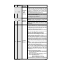
12-pin Accessories Harness
Wire
Colour
1
BLUE
2
BROWN
3
GREEN
4
WHITE /
BROWN
5
WHITE /
GREEN
6
BLUE /
WHITE
7
WHITE /
ORANGE
8
ORANGE
P. 6
Function
Description
500 mA negative output. This output can be used to control
the Trunk release (1-sec. pulse), or it can be set to operate
as a constant output as long as the TRUNK button is held
pressed (for Sunroof or Window closure)
(–) Lock
Programmable 500 mA negative output: 1/10-sec., 7/10output
sec. or 4-sec. pulse
Programmable 500 mA negative output: 1/10-sec., 7/10(–) Unlock
sec., 4-sec. or double 1/4-sec. pulse (ON 250 ms, OFF
output
500 ms, ON 250 ms).
500 mA ground signal when the Doors are locked by
remote control. This wire will go to ground 1/2 sec. before
the LOCK pulse, and go out 1/8 sec after LOCK. The wire
(–) Rearm
must be connected to the OEM Arm wire (usually the Door
output
Pin).
Note: The System will also give a Rearm pulse on this wire
when it shuts down the vehicle after a remote start.
500 mA ground pulse when the Doors are unlocked by
remote control. Connect to the OEM Disarm wire of the
(–) Disarm
vehicle.
output
Note: The system will also give a Disarm pulse on this wire
before every remote start.
This input should be used in vehicles with positiveswitching Door pins or Dome Light circuits. Connect to the
(+) Positive Dome Light wire that tests +12 V when a Door is open.
Door input Caution! The installer should use either the positive or the
negative Door input. Never use both of them
simultaneously.
This wire will provide a constant 500 mA output when the
system is armed (locked by remote control). It can be
connected to an external Starter Interrupt Relay.
This wire should be connected to a Single Pole Double(–) Starter Kill Throw Relay: this wire will connect to Pin 85 on the Relay,
and Pin 86 will be connected to the Ignition wire.
output
The Starter Kill output becomes active during remote starts.
(armed
One benefit of the Starter Kill is the Anti-Grind feature.
output)
Once the vehicle has been remote started, the Anti-Grind
prevents the Starter Motor from re-engaging when the
Ignition Key is inserted in the Ignition Switch and
accidentally turned to the CRANK position.
N/A
This wire is not used.
(–) Trunk /
AUX 3
output
Installation Guide